

Page 1
Rockers – DGRL, DGRM,
DSRL & DSRM series
OPERATING MANUAL
DGRL-01-01
Dynalab Corp.
November 2017
DGRM-01-02
1
Page 2
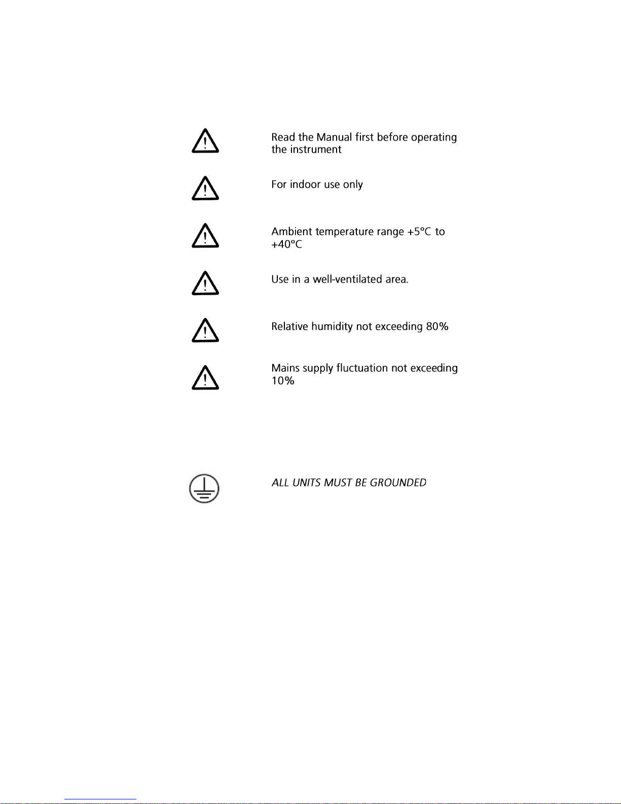
BEFORE USE:
Please read the following instructions:
Warning
Check the line supply is sufficient to meet the power requirement of the unit!
2
Page 3

Warranty
Dynalab Corp. provides a 90 day warranty for the units in this series.
This warranty does NOT apply if damage is caused by fire, accident, misuse, neglect,
incorrect adjustment or repair, damage caused by incorrect installation, adaptation,
modification, fitting of non-approved parts or repair by unauthorized personnel. When
returned the defective products, customers should be responsible for the shipping and
insurance costs
LIMITATION OF LIABILITY
NOTWITHSTANDING ANY OTHER PROVISIONS HEREIN, UNDER NO CIRCUMSTANCES IS
EITHER PARTY LIABLE FOR ANYCONSEQUENTIAL, SPECIAL, INCIDENTAL, INDIRECT,
MULTIPLE, ADMINISTRATIVE, OR PUNITIVE DAMAGES, OR ANY DAMAGE OF AN INDIRECT
OR CONSEQUENTIAL NATURE ARISING OUT OF OR RELATED TO ITS PERFORMANCE,
WHETNER BASED UPON BREACH OF AGREEMENT, WARRANTY, OR NEGLIGENCE AND
WHETHER GROUNDED IN TORT, CONTRACT, CIVIL LAW, OR OTHER THEORIES OF LIABILITY,
INCLUDING STRICT LIABILITY, EVEN IF ADVISED IN ADVANCE OF THE POSSIBILITY OF SUCH
DAMAGES. THE COMPANY’S TOTAL LIABILITY INCLUDING, BUT NOT LIMITED TO, LIABILITY
FOR INDEMNITY, DEFENSE, AND HOLD HARMLESS OBLIGATIONS IS LIMITED TO NO MORE
THAN THE AMOUNT PAID TO THE COMPANY UNDER THE CUSTOMER’S ORDER AND THE
CUSTOMER AGREES TO INDEMNIFY THE COMPANY FOR ANY EXCESS AMOUNTS. TO THE
EXTENT THAT THIS LIMITATION OF LIABILITY CONFLICTS WITH ANY OTHER PROVISION(S)
OF THIS AGREEMENT, SUCH PROVISION(S) WILL BE REGARDED AS AMENDED TO
WHATEVER EXTENT REQUIRED TO MAKE SUCH PROVISION(S) CONSISTENT WITH THIS
PROVISION
3
Page 4

Overview
Rockers – The platform on the mixers move in non-horizontal direction as the motor rotated,
i.e. the rocking movement. There are two types of rockers provided: 1, the gyration type
and the wave type. With tilted angle in one end, the gyration mixers gyrate in threedimension. This mixing action is suitable for full flashing some floated object by liquid, such
as staining and de-staining gels and low foaming mixing purpose. The wave type is based on
see-saw action to create wave-like mixing of the liquid and suitable for Petri-dish and culture
fl
4
Page 5

Figure 4: Overview of the mini scale 3D gyrator rocker (RCK-31). ① Electrical socket;
② Slip-proof platform; ③ LED display on Digital front panel
Figure 5: Overview of the lab scale see-saw rocker (RCK-21). ① Electrical socket; ②
Slip-proof platform; ③ Digital front panel
5
Page 6

Operation
Always install the carrier or platform before turning on the machine. All platforms or
carriers are shipped in pre-installed status. For safety reason, please check all the locking
screw and tighten again if necessary. The locking screws might be loosened during
transportation!
Place the machines on the flat and steady surface and keep away from other objects for
safe operation.
Check the electrical safety status and the power switch must be in “OFF” position before
plug into the power outlet. The machines come with IEC electrical socket and double fuses
for safety operation.
For the 3D Gyrator Rockers, adjust the tilted angle before loading the samples. Set the
speed to the minimum rpm. And examine the nut underneath the center cylinder shaft
turning front, then stop the machines and tilt the platform to desired angle.
Figure 13: Overview of head box .
Load the samples first before turning on the machine. Be aware of loading sample evenly
and never overload the samples.
Always start with low speed and gradually adjust the speed, especially for the analog
model.
There are two different types of control in most of the mixers: digital and analog. Both
control modes can adjust the speed and timer of the mixers.
1. Digital Control of Speed and Timers
Figure 14: Overview of the front panel of the digital control mode. ①Start/stop
button; ②Mode button; ③Indicator beneath “rpm”; ④ Indicator beneath “time”
There are two buttons and one knob on the digital panel: The knob is the main switch for
turning on the machine and adjusting the speed and timer; the mode button has the
6
Page 7

selection function to either adjust the timer or the speed; the start/stop button is used to
start or stop the mixing process. The panel has LED numeric display and red indicators.
When starting the mixers, the red indicator between the start/stop and mode buttons
illuminate, and when pressing the mode button, the read indicators underneath the rpm
and minute alternatively illuminate to show the status of display.
1.1 Press the knob to turn on the unit. The LED display the number of last saved rpm and
timer setting. And the indicator underneath the rpm illuminate, adjust the rpm by the knob
to desired value. And move the illuminated indicator from underneath rpm to minute by
pressing the mode button, the display will show the set timer and change to the desired
timing value, and finally press the start/stop button to start the machine. If using the knob
to turn off the machine, the set timer and speed will automatically be saved, and carry on
the next time operation.
1.2 Adjust the timer: press mode button until the indicator underneath of min illuminate,
turn the knob to desired count-down minute. To disable the timer, just turn the knob to ---,
the unit will continuously operate until manually stopping the unit. When the timer reaches
to zero, the unit stops and sounds an alert.
The default time unit is minute (displayed nnnn), but it can be changed to Hour: Minute
(displayed H:nn) or Minute: Second (displayed nn:ss). To do so, turn off the machine
completely with the main electrical switch, press the knob and mode button simultaneously,
and turn the machine back on. The display will display 88:88 and then off. Turn the
machine on using the knob, the display will show nn:ss (for minute: second) or H:nn (for
hour : minute) or nn (for minute), and turn the knob to the desired unit and press the knob
again to turn off the machine, the display will show OFF. When turning on the machine next
time, the newly set unit will take effect.
1.3 The speed and timer can be adjusted during operation without stopping the machine.
Suggest users to use lower speed to start the machine and adjust the speed to optimum
mixing status slowly to avoid the spill or safety problems during the operation.
2. Analog Control of Speed and Timers
Figure 15: Overview of the front panel of the analog control mode. ①Timer knob;
②Main switch; ③Speed knob
7
Page 8

There are two knobs and one main switch on the front panel of the analog types of the
mixers. The main switch has three stages function: ON, OFF and Timer. For continuous
operation, place the switch to the “ON” position, and turn the rpm knob (on the right hand
side) to desired speed. When using timer, place the switch to “Timer” position, and adjust
the speed using speed knob. Before turning on the machine, please turn the speed knob all
the way to the left hand side (minimum level)! And adjust the speed gradually.
3. The temperature setting of the mixer incubator (*MI series)
The mixer incubators have two separate control panels: The bottom panel is for the control
of speed and timing which is exactly the same setting procedures describe above; and the
top control panel is for temperature control (see Figure 16). To set the temperature, hold
the set button, and turn the knob to the desired temperature. After release the set button,
the temperature setting takes in effect immediately. For CMI-100, the temperature can only
be set from 5˚C above room temperature to 60 ˚C maximum.
Maintenance and Service
This range of equipment only requires routine cleaning for the maintenance. Before
cleaning, Always unplug the equipment from the electrical outlet. Use soft cloth with mild
detergent to clean the surface of the equipment.
Dynalab Corp. | 175 Humboldt Street, Suite 300 | Rochester, NY 14610
Tel: 800-334-7585 | Fax: 585-334-0241
www.dynalon.com | E: dynaloninfo@dyna-labware.com
8
 Loading...