

Dynalab DB-3-200-01, DB-3-130-01, DB-2-130-01, DB-2-200-01, DB-2-200-02 Operating Manual
...Page 1
BLOCK HEATER – MODELS DB-3-200-01, DB-3-130-01,
DB-2-130-01, DB-2-200-01, DB-2-200-02,
DB-1-130-01 and DB-1-200-01
OPERATING MANUAL
VERSION 3.11
Dynalab Corp., Inc.
November 2017
v1.0
1
Page 2
BEFORE USE:
Please read the following instructions:
Warning
Check the line supply is sufficient to meet the power requirement of the unit!
2
Page 3

Warranty
Dynalab Corp. provides a 90 day warranty for the block heater.
This warranty does NOT apply if damage is caused by fire, accident, misuse, neglect,
incorrect adjustment or repair, damage caused by incorrect installation, adaptation,
modification, fitting of non-approved parts or repair by unauthorized personnel. When
returned the defective products, customers should be responsible for the shipping and
insurance costs
LIMITATION OF LIABILITY
NOTWITHSTANDING ANY OTHER PROVISIONS HEREIN, UNDER NO CIRCUMSTANCES IS
EITHER PARTY LIABLE FOR ANYCONSEQUENTIAL, SPECIAL, INCIDENTAL, INDIRECT,
MULTIPLE, ADMINISTRATIVE, OR PUNITIVE DAMAGES, OR ANY DAMAGE OF AN INDIRECT
OR CONSEQUENTIAL NATURE ARISING OUT OF OR RELATED TO ITS PERFORMANCE,
WHETNER BASED UPON BREACH OF AGREEMENT, WARRANTY, OR NEGLIGENCE AND
WHETHER GROUNDED IN TORT, CONTRACT, CIVIL LAW, OR OTHER THEORIES OF LIABILITY,
INCLUDING STRICT LIABILITY, EVEN IF ADVISED IN ADVANCE OF THE POSSIBILITY OF SUCH
DAMAGES. THE COMPANY’S TOTAL LIABILITY INCLUDING, BUT NOT LIMITED TO, LIABILITY
FOR INDEMNITY, DEFENSE, AND HOLD HARMLESS OBLIGATIONS IS LIMITED TO NO MORE
THAN THE AMOUNT PAID TO THE COMPANY UNDER THE CUSTOMER’S ORDER AND THE
CUSTOMER AGREES TO INDEMNIFY THE COMPANY FOR ANY EXCESS AMOUNTS. TO THE
EXTENT THAT THIS LIMITATION OF LIABILITY CONFLICTS WITH ANY OTHER PROVISION(S)
OF THIS AGREEMENT, SUCH PROVISION(S) WILL BE REGARDED AS AMENDED TO WHATEVER EXTENT REQUIRED TO MAKE SUCH PROVISION(S) CONSISTENT WITH THIS PROVISION
Overview
DB-3-200-01 and DB-3-130-01 are designed to accommodate three different format aluminum blocks. And it comes with block handling tool (see Figure 2) and glass thermometer.
DB-3-200-01 has the digital display and simple operation buttons to fit the needs of users in
the lab and has two lights to indicate the status of the operation and process.
3
Page 4

Operation of Analog Unit
1. Select the appropriate block. Make certain that the block is clean on all sides as well as
the hot plate of the unit. This will ensure proper heat conduction.
2. Place the block into the well of the unit and insert the proper tubes into the block. Make
sure there is a good fit between tube and well.
3. Plug in Mains Cable and turn the unit on in the back of the unit.
Setting Operating Temperature Analog Unit
1. Turn the Temperature Control Knob on in the front of the unit to the required setting
(OFF or 1-9). The actual temperature of the block depends on the type of block and fit.
Thermal contact between block and unit is crucial for best results.
2. Different designs of insert blocks may cause actual temperatures to vary and speed of
heating to vary. Place a thermometer in the special thermometer hole in one of the
aluminum blocks to indicate proper temperature.
3. The unit will heat if the set temperature is higher than the current block temperature.
This will be indicated by the heater indicator light.
4. The heater indicator light will begin to flash when the set temperature is approached. It
will flash more slowly when the temperature is beginning to stabilize.
Please note there will be a lag time between the heater and the block.
Operation of Digital Unit
For the digital: DB-3-200-01, DB-2-200-01, DB-2-200-02 and DB-1-200-01:
1. Put the block into the blocks compartment (see Figure 1A), use block handling tool
(Figure 1B) to add and remove the block
2. Plug the power cord to the source, and make sure that the plug is firmly pressed. Turning
on the switch on the back, and the light in the front will be on. The light will be flashing until
the temperature reaches equilibrium. Use thermometer measuring the temperature, turn
the knob to adjust temperature. Leave the Heated Block on to keep the temperature at
stable level. It takes sometimes to reach the equilibrium.
ALWAYS KEEP THE MACHINE AWAY FROM DRAFTY AREA TO AVOID THE EFFECT OF THE
ENVIRONMENTAL TEMPERAURE ON THE TEMPERATURE CONTROL OF THE BLOCK HEATERS!
4
Page 5
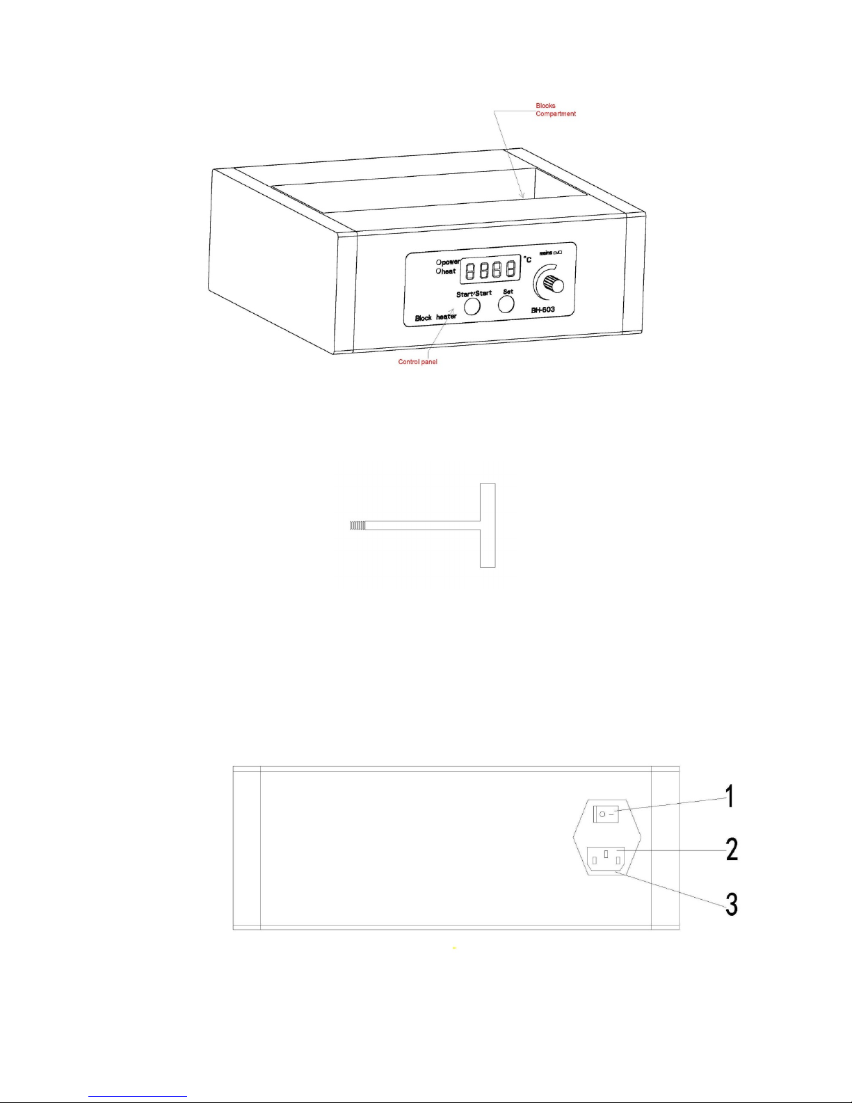
Figure1A.
Figure1B. Removing Tool
2. Plug the power cord to the source, and make sure that the plug is firmly pressed. Turn on
the machine by switching the on/off switch (see Figure 2).
Figure 2: The rear view of the Block Heater. 1, on/off switch; 2, IEC power inlet; 3,
fuse holder
5
Page 6
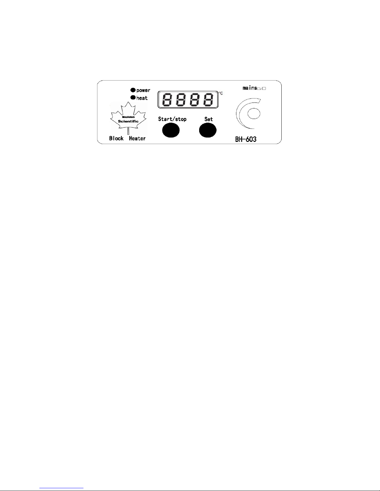
3. When turning on the machine, the display will immediately show “_ _ _ _”, and then
shows the actual temperature in Celsius. The “power” light is off at this time. And when the
block temperature is over 50 ˚C, the “heat” light is on, otherwise, it is off, too.
Figure 3: The front panel view of the DB-3-200-01
4. Setting Operating Temperature:
- Turn the Temperature Control Knob on in the front of the unit to the required setting (OFF
or 1-9). The actual temperature of the block depends on the type of block and fit. Thermal
contact between block and unit is crucial for best results.
- Different designs of insert blocks may cause actual temperatures to vary and speed of
heating to vary. Place a thermometer in the special thermometer hole in one of the
aluminum blocks to indicate proper temperature.
- The unit will heat if the set temperature is higher than the current block temperature. This
will be indicated by the heater indicator light.
- The heater indicator light will begin to flash when the set temperature is approached. It
will flash more slowly when the temperature is beginning to stabilize.
- Please note there will be a lag time between the heater and the block.
5. Press “Start/stop” button to start the operation. The “power” light is on and “heat” light
is flashing at this point. When reaching the equilibrium, the “heat” light is steady on. The
equilibrium point is set @ 0.1 degree of the accuracy. It might take longer time to reach.
Caution: when putting the cold test tubes or other vials, it may cause the tubes/vials
to break!
6. When running, i.e. the “power” light on, the set point of the heated block could not be
changed. To change the set point of the temperature, press “Start/stop” button to stop the
run (the “power” light will go off), and then change the set point as indicated in the step 4.
7. The DB-3-200-01 always shows the actual temperature reading. To see the set point
temperature, press the “Set” button, and the LED will show the set point temperature.
8. After use, wait until the block cool down to below 50 degrees (the “heat” light is off) and
turn off the block heater.
6
Page 7

Calibration
The digital types of Block Heaters can easily be calibrated to show any blocks/vials and
tubes’ temperature in the displayed LED. Due to the differences in the mass of the various
aluminum blocks, environmental air temperature, thermal radiation, and many other factors,
the Block Heater may need to be re-calibrated when switching different blocks and when the
environmental changed. The DB-3-200-01 has been calibrated based on 16 mm Blocks.
DB-3-200-01 can be calibrated using one to five points. The calibration steps are described
in the followings:
1. Prepare the thermistor, or thermometer temperature measurement devices. You can
calibrate the block or even the temperature of the solution in the vials/tubes. Make sure
the thermistor or sensor well contacted with the blocks or vials/tubes solution.
2. Calibration could not be made during running (i.e. the “Power” light on). Press
“Start/stop” button first to stop run if the machine is running.
3. Press “mains” turning knob (please note that it should be “press” not “turn”) first, then
press “Start/stop” button, simultaneously release both, the display will show “C _ _ X”,
which X indicates the stage of the calibration. For example, in the first calibration, it will
display “C _ _ 1”.
4. Press “set” button, and turn the “mains” turning knob to the desired temperature
calibration point, release the “set” button, and press “mains” to start the calibration. In this
time, the “power” light will be on, and the “heat” light will be flashing. The display showed
“C _ _ X” flashing.
5. When reaching the equilibrium set temperature, the display will stop flashing. In this
stage, you can enter the actual block or vial temperature from reading the block or vial
temperature from external temperature measurement device: Press “set” button and
turning the “mains” knob to the actual temperature value, release the “set” button, and
press the “mains” knob. The machine will take the real value to take effect in the next run.
In this case the CL-201 will display “C _ _ X+1” (X + 1 indicates the next number of the
calibration stage) and continue to flash: Repeat the step 4 to enter the next calibration set
temperature.
The maximum calibration point is five. When finishing five point of the calibration, the
machine will automatically exit from the calibration program and return to the pre-start
status: the “power” light will go off and the “heat” light will go “on” when temperature is
over 50 ˚C.
6. The calibration can be interrupted anytime by pressing “Start/stop” button and “mains”
knob as indicated in step 3: If the process interrupted before the completion of the
calibration stage, the machine will only take the previous calibration point. For example, if
the process interrupted between the first and second point calibration stages, then the
machine will take the first calibration point and becomes one-point calibration; If the
7
Page 8
process interrupted between stage 4 and 5, then the machine will take the previous 4 points
data as the calibrated value, and becomes 4-points calibration.
7. During calibration, the calibration set point could not be changed unless interrupting the
process by pressing the “Start/stop” and “mains” knob as indicated in the step 3.
8. Always using the same type of the block to avoid the discrepancy. The calibrated
displayed value only accurately indicates the value of the block/vial that actually measured
from external temperature measurement device.
For DB-2-200-02:
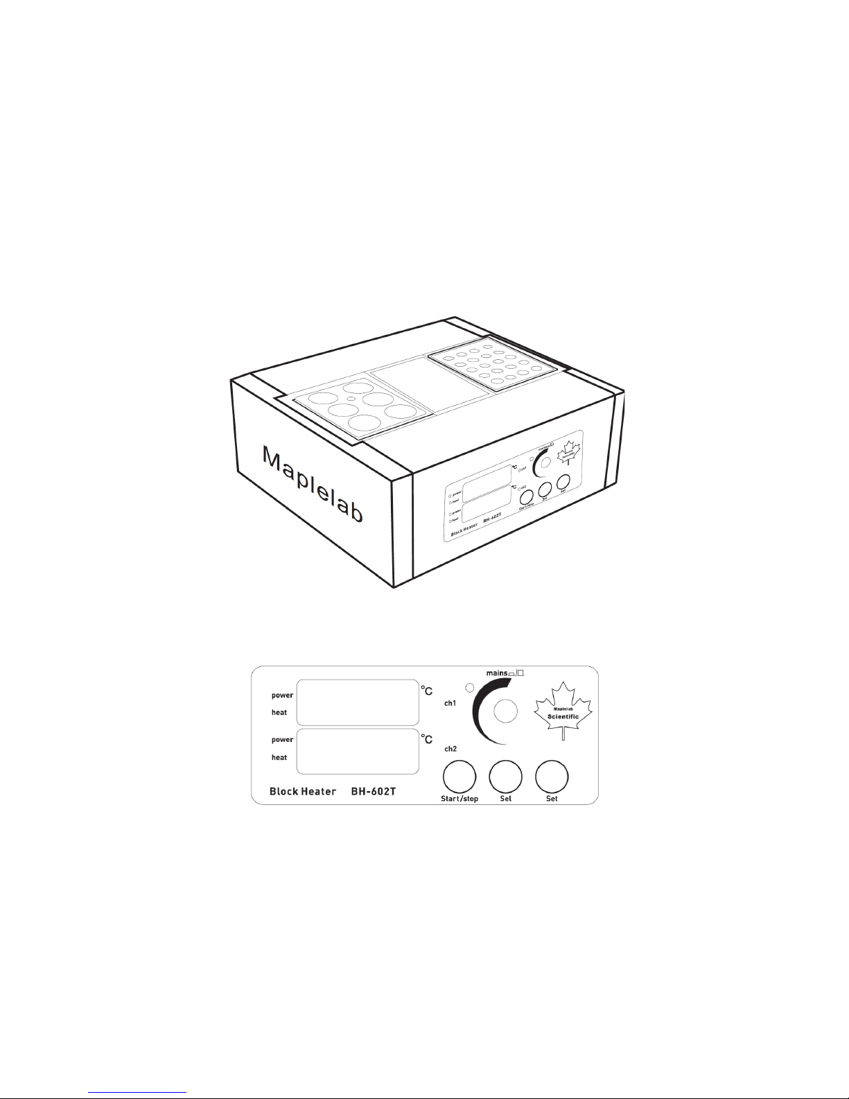
Figure 4: DB-2-200-02 Overview: Ch1: The left hand side (with six-hole block); Ch2:
The right hand side with 20 hole block)
Figure 5: The front panel view of the DB-2-200-02
Please make sure that the correct channel corresponding to the designated block
before to do the operation. The DB-2-200-02comes with additional LED display
and “sel” button for users to select the channel. All operation and calibration is
the same as in DB-3-200-01, but before to do that, please press the “sel” button to
select the channel (the LED light will be ON when the channel got selected).
8
Page 9

Selection of the Aluminum Blocks
Working temperature range Ambient
+5°C to 200°C
Temperature display
4 digit LED
Set point resolution
0.1°C
We provide various aluminum blocks to accommodate different vials/tubes:
Part Number Tube size (Diameter or ml) Number of the holes
Hole sizes (Diameter X Depth)
in mm
DB0001 27 mm 6 26.75 X 48
DB0002 0.5 ml 30 7.9 X 15.6 + 11.2, 9° taper
DB0003 0.2 ml 96 6.0 X 17.3, 9° taper
DB0005 1.5 ml 20 10.7 X 22.5 + 13, 9° taper
DB0006 50 ml Flat bottom 2 45 X 46
DB0007 10 mm 20 10.8 X 35
DB0009 2 ml 20 10.5 X 33
DB0010 13 mm 20 13.5 X47
DB0013 1.5 ml 20 10.7 X 14, 9° taper
DB0015 12 mm 20 12.5 X 47
DB 0015-33 12 mm 20 12.5 X 33
DB0016 16 mm 12 16.5 X 47
DB0017 2 ml 20 10.5 X 47
DB0018 19 mm Block 8 19.5 X 47
DB0019 33 mm Block 4 33.5 X 47
Technical Specification
Settable temperature range 0.0°C to 200.0°C
Temperature stability ±0.1°C at 40°C
Temperature stability ±0.15°C at 100°C
Set point to accuracy ±1°C
Electrical supply Voltage Cycles Power
230V 50Hz-60Hz 650W or
110V-120V 50Hz-60Hz 650W
9
Page 10

Declaration of Conformity
These products listed in this manual comply with EN 61326-1: 2006 and fulfill EMC testing
requirement of Medical Device Directive (2004/108/EC) listed in the report number
CE2012-OTE8003E; and EN 61010-1 plus EN 61010-2-010: 2003 of the LVD directive2006/95/EC in the listed report numberCE2012-AVE8006S.
mark affixed’2012
Signed:
Date:
10
Page 11

Model
1. Integrity
3. Correct warning label
5. Electrical Insulation
6. Electrical Flash Test
2. Appropriate control function
Inspection Report
Serial Number
Safety
√
2. Packing status
4. Electrical earth continuity
Functional 1. Visual acceptance
3. Indicators
Quality Control Inspector
√
√
√
√
√
√
√
√
Dynalab Corp. | 175 Humboldt Street, Suite 300 | Rochester, NY 14610
Tel: 800-334-7585 | Fax: 585-334-0241
www.dynalon.com | E: dynaloninfo@dyna-labware.com
11
 Loading...