

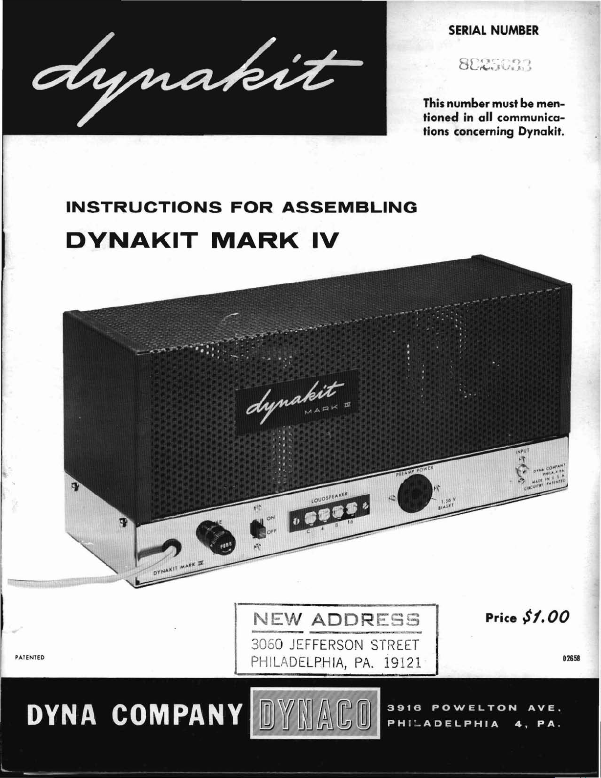
Dynakit MArk IV Instructions For Assembling
SERIAL
NUMBER
INSTRUCTIONS
DVNAKIT
FOR
MARK
ASSEMBLING
IV
0'.'-
8[
'~.J.'
This
numbermustbemen-
in
tioned
tions concerning Dynakit.
all communica-
...
f'")
~
/,
Jt,
.•
PATENTED
3060
JEFFERSON
PHILADELPHIA,
STREET
PA.
19121
Price
$1.00
1)2658
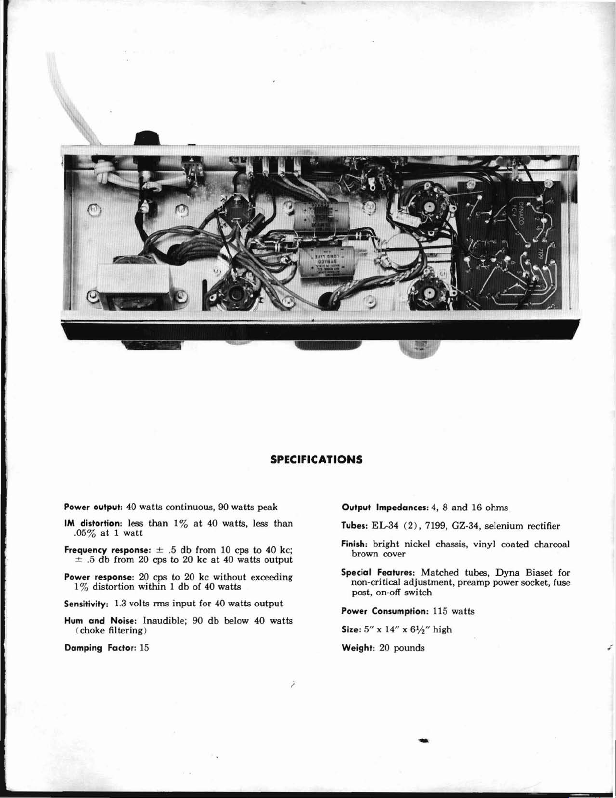
SPECIFICATIONS
Power output: 40
1M
distortion: less
.05%at1
watt
watts
continuous, 90
than
1%at40 watts, less
Frequency response: ±.5db
±
.5dbfrom 20 cps to 20kcat
Power response: 20
1
%
distortion
Sensitivity: 1.3 volts rms
Hum
and
Noise: Inaudible; 90
cps
to
within1db
input
(choke filtering)
Damping
Fador:
15
watts
peak
from 10 cps to 40 kc;
40 watts
20 kc
of 40
for 40
without
watts
db
exceeding
watts
output
below 40
than
output
watts
Output Impedances: 4, 8
Tubes:
Finish:
EL-34
bright
(2),
nickel chassis, vinyl coated charcoal
and
16 ohms
7199, GZ-34, selenium rectifier
brown cover
Special Features:
non-cri tical
adjustment,
Matched
tubes,
preamp
Dyna
Biaset for
power socket, fuse
post, on-off switch
Power Consumption: 115
Size: 5" x 14" x
Weight: 20
i
6%"
pounds
watts
high

INSTRUCTIONS FOR ASSEMBLING DYNAKIT
MARK
IV
DESCRIPTION
The
MarkIVAmplifier uses a
basedonthatofthe
which
have
become world famous for
while essentially
7199
tube
is usedasa
plifier
directly
All
parameters
This
typeofphase
that
its
operationisindependentoftube
no
adjustments
performance.
An
internal
phase
arrangement
signals to
ated
tubes use a fixed. bias
through useofDyna
provides
mizes
connection of
centage
lationofthe
uncritical of load impedance.
in
a very wide
negative voltage feedback lowers
unmeasurable
andtoless
40
stages
it
high
or
stability,
on
operated,
inverteratthe
the
well below
optimum
the
effects of
of screen loading which improves
output
The
impedance
the
output
dynamic
than
watts
output.
The
use of a
along
with
possible to
and
low frequencies.
means
that
there
oscillation
The
inherent
and
the
printed
completely non-critical.
highest
rior
and
dependable
time.
GENERAL
Assembly of
comparedtogeneral
is because all
assembled for
Other
parts
are
tered
layoutsothere
or
trouble shooting purposes. Con<;truction of
Dynakit
causeofthese
the
nents;
pictorial
Upon
parts
should
opening
list.
they
diagram
can
Dynakits
simple
coupledtoa
are
are
capacitive
provides
output
their
the
output
stage
proportionatnormal listening levels
minimum
have
is no
under
linearityofthe
the
prefabrication
circuit
the
critical
you
outinthe
not
simplifications.
your
Familiarize
be identified by
and
pentode
adjusted
inverter
requiredinmaintaining
feedback loop balances
highest
accurately
tubes, which
maximum
arrangement
Biaset
linearityofthe
unbalanced
tubes includes a small per-
stage
and
match
and
provide
range.
1%
intermodulation
careful
unconditional
tendency
any
condition
assembly
The
quality
operation
WIRING
Dynakit
kit
assembly requirements.
partsofthe
on
the
is easy accessibility for wiring
take
kit, check
andbyspecified color coding.
circuit
MarkIIand
superior
trouble
cathodyne
for
has
(patent
makesitcomparatively
bias conditions utilized
minimum
In
numberofphase
transformer
This
components insures supe-
MarkIVis
printed
open
more
yourself with
free.
high
gain
phase
minimum
the
unique
frequencies,
balanced driving
are
ratings.
pending)
tubes
components.
distortion
addition,20DB
the
distortiontoan
stabilityatboth
feature of
toward
of use.
circuit, its
of all critical wiring
make
use of conservatively
over a long period of
PRACTICE
Dynakit
circuit
in a free
than
three hours be-
the
components
comparison
arrangement
Mark
III
quality
The
new
voltage am-
inverter.
distortion.
advantage
aging so
EL-34's oper-
The
which is
distortion
design makes
motorboating
construction
quite
and
that
optimum
and
output
which
and
mini-
The
the
regu-
over
shifting
the
design
absolute
simple
This
are
factory
assembly.
unclut-
your
with
the
compo-
with
the
the
set
the
of
at
Tools required for easy assemblyofyour
are
a soldering
long nose pliers, screwdriver,
though
cutterofthe
thanadollar
ping
satIsfactory results from
ALL
ROSIN
any
used.
"Rosin
of which is doubtful,itis wisetoobtain
or
required,
"(S)
is specified,itindicates
be
the
touched to
soldertothe
iron
be held in place for a few seconds
it
the
It
transition
and
mechanical security.Itis
around
ing together
there should be no
wiggled
soldering
:ating.
III
be used with discretion since
availableisfar more
wires.
used;
nection
strain
cised
they
for simplified procedure in which
done
tions of
structions
ing off each
diagrams
nections Checked
next step.
each
work
not
the
various leadsinthe
c,;ood
soldering technique is
SOLDERING
CORE
equipmentinwhich
Make
Core."Ifyou
60/40
".Ifthis symbol is
madeatthat
Soldering is accomplishedbyheating
iron
and
joint. After
is seen
connection-the
should
Before
the lead
contacts
withapair
A small
confined space.Ifa soldering gunisused
Component
the
can
on lugs or components.
not
are
actually
The
instructions which follow have been
without
the
step
without
iron
(small
essential, a low
type
which
win
greatly
SOLDER.
sure
that
have
rosin core solder.
the
assembly
point
before soldering.
until solder is
the
joint.Itis
iron.Itshould
the
that
the
solder
lug
not
show a ballofsolder,
from solder to
applying
with
length should be
to allow wires to touch
be followedona
should be used for reference
If
checked carefully,
solder
shouldbecrimped in
many
times. A single
with
pliers is suitable. After soldering
playatthe
of pliers.Itis practical todoall
a pencil
tipisextremely useful when working
than
leads
should
be
made
connectf::.j to the
interference between
wiring.Itis recommended
stepasit
against
the wiring is done methodically
difficultyassoonasit
tip)
or
and
wire
cost
wire
canbepurchased
facilitate
any
MUST
Thereisno
acid
the
solderisplainly
solderonhand
instructions
not
shown
that
hot
not
solder
has
and
component
the
not
type
required
such
from
stepbystep
is completed.
these before going on to
cutting
kit.
valuableinobtaining
electronic equipment.
BE
DONE
core solder has been
Whenever
after
further
be fedtothe
contacted
the
iron
be trimmed as
pointtopoint
connections will
enough to
desirabletofeed
flows,
and
wire connectedtoit.
lead.
joint
shouldbec1e.an
placesoas
necessary to
joint
wi~h
the
amount
fOl'
that
Care
should
one
same
the
the
your
amplifier
soldering gun,
the
removed when
turn
soldering
the
another
is completed.
Dynaldt
cutters. Al-
stripper
warranty
soldering is
specifyitby
a connection
the
iron
both
hut
if the )Pad is
a low
proper
point.
work can be
various por-
that
basis, check-
The
and
for less
and
strip-
WITH
marked
the
origin
new
50/50
joint
flow
when
junction
should
parts
a smooth
to have
wrap
leads
and
pinch-
wattage
it
should
of
they
without
be exer·
unless
arranged
the in-
pictorial
all con-
should
and
on
with
the
heat
light
are
con-
tlw
and
of
of
Refer
1
2
3
4
5
6
7
8
9
10
11
MECHANICAL
Pictorial
Mount
( )
screws,
est
screws
small
a
of
each
that
showninthe
the
screws from
mount
each
Mount
of
the
lockwashers.
Using#4hardware,
terminal
chassis.
Mount
with
are
not
the
positionofthe
pictorial.
Mount
provided.
outsideofthe
only
mounted.
Insert
at
the
Mount
in
the
sockets.
insert
at
the
Note
Mount
solder
Insert
the
terminal
the
small
With
clamp
Feed
former, PA-135,
provided.
place
nearest
lockwashers
bottom,
ing
two
fastcn
#8
hardware.
former
nexttothe
clamp
(J )
Mount
the
remaining
the
chassis.
orange,
ASSEMBLY
Diagrams
the
nuts,
supplied).
slotorkeywayinthe
socket;besureineach
this
keywayisproperly
the
sockets
screw
withanut
the
chassis
strip
the
#4 screws.
necessaryinthis
the
fuse
The
one
correct
the
rubber
endofthe
the
10,000
%" hole
Put
the
controlinthe
top
of chassis
orientationofconnecting
the
five lug
lugatthe
a #4 screw from
solder
#4
hardware,
loosely
all
the
with
the
place
transformer
bothinplace
leads
rectifier socket;
maybetightened.
the
output
and
for
LocationofParts
four
octal
sockets
and
lockwashers
Note
pictorial
the
input
using#4screws,
on
slide
post
rubber
chassis.
the
strip
lug,
near
wires
Fasten
two
frontofthe
and
the
All
go
setofholc-t;atthe
Note
yellow leads
diagrams.
topofthe
from
the
and
socket
mount
the
switch
Nuts
and
connecting
with
bushing
Note
way
for
grommetinthe
chassis.
ohm
bias
near
the
lockwasheronthe
with
terminal
centerofthe
the
over
then
mount
the
single
of
the
through
the
#8
screws in
chassis
nut<>.
choke
over
mounting
with
but
the
under
the
transformer,
that
the
inside.
lockwasher.
from
the
outside of
from
instance.
the
the
potentiometer
hole
outside.
the
the#4nut.
the
transformer
Now,
two
come
with
(the
small-
that
there
center
hole
instance
oriented
Insert
chassis
lockwashers
lugs in
special
goesonthe
that
pair
and
the
strip
screw,
octal
power
single
the
more
black trans-
cable
and
black, brown
and
Fasten
the
inside
nuts,
and
four screw
the
the
inside
Follow
the
nut
there
posttobe
%"
hole
of
octal
shaft,
fasten
%"
nut.
lugs.
and
the
chassis.
Place
then
the
cable
socket.
trans-
hole
the
holes
using
from
the
remain-
holes
and
sets
clamp
then
this
A-470,
center
through
#4
as
#8
on
in
of
of
the
hole
near
the
four screw
strip.
transformer.
12
is
Each
approximately
end
maybetrimmed
1
2
is
3
4
5
6
7
8
9
10
Mount
pacitorinthe
symbolsatthe
lug.
in
giving
ter
snugly
lengthofhookup
unless
(j)
Connect
mer
B of
(-J;
Connect
leadtopin
nect
socket
Twist
nect
nect
VI
Twist
leads
socket
one
and
of
Connect
lug
lug
Connect
Connect
circle)ofthe
nect
(~
)
Connect
output
screw
lead to lug
lead
lead to lug #4.
Connect
themtosockets
TORIAL.
to pin #3 of
green/white
These
the
turn
WIRING
%" of
otherwise
as
leadstolug
(8).
Connect
the
the
position
one
the
(8).
green
the
Connect
the
at
strip,
the
five lug
the
the
filter
terminal
to lug
to lug
the
remaining
Use
#8
hardware
the
quadruple
special
baseofeach
shouldbeorientedasshown
pictorial.
eachofthe
while
against
the
cutout.
Fasten
mounting
holding
chassis.
section
the
INSTRUCTIONS
wire
specified
insulation
specified.
required
oneofthe
the
fuse
one
yellow power
#2ofsocket
other
VI.
the
two red
them
red leadtopin
other
the
two green power
together
V2.
8EE
leadtopin
other
green
the
green/yellow
five lug
the
red/yellow
the
mounting
the
red/black
strip.
one
choke
quad
other
capacitor.
the
black
transformer
#2
#3
the
red
#2ofthe
Connect
socket
leadtolug
'stripped
Transformer
for a
/
post
yellow
around
red
and
terminal
choke
strip.
(8).
(8).
output
leads
V2
neat
black
#2ofthe
other
black
(8).
leadtopin
leads
socket
lead
position
PICTORIAL.
#2ofsocket
lead to
strip.
screw of
lead
leadtoJug #1 (semi-
filter
capacitor.
leadtolug
lead
to lug # I of
Connect
Connect
Connect
transformer
filter
capacitor.
together
and
the
blue/white
V2
(8).
#4 of
terminal
to
secure
Observe
connecting
capacitor
lugsaquar-
the
should
from
wiring
power transfor-
slide
leadtolug
transformer
V1
(8).
together
#4
(8).
to
pin
transformer
pin#7of
lead
lead
to lug#4of
of
the
the
the
the
and
V3.
8EE
Connect
socket
the
filter ca-
the
capacitor
have
each
leads
job.
switch
Con-
#8
and
VI.
Con-
Con-
#6
them
Connect
V2,
V2.
to lug
to
solder
the
five
Con-
#2
A-470
the
four
brown
orange
yellow
lead
Twist
carry
PIC-
lead
the
V2
by
#2
of
of
to
of
-
2
11
12
13
14
15
16
17
18
19
20
21
22
23
(S).
Connect
(S).
V3
#4
of V3.
Connect
the
Connect
one
end
blue
lead to
the
green
of a 10,000
pin#3of
leadtopin
(brown-black-orange) resistor to lug
of
the
five
lug
strip.
end
to lug #1 of
tentiometer
Connect
selenium
lug
strip
endtolug
Connect
mfd
bias
lug
strip
(S).
the positive
rectifiertolug
(S).
#5 of
the
negative
capacitor
(S).
endtolug#3of
Connect
other50mfd
the
to
lug#2of
five
lug
the
positive
bias
strip.
the
Connect
the
10,000
(+)
Connect
the
the
strip.
(-)
to lug
Connect
the
the
strip.
(+)
capacitortolug#3of
Connect
10,000
ohm
the
ohm
bias po-
end
#4ofthe
negative
end
of a 50
#5ofthe
positive
end
the
other
bias poten-
tiometer.
Connect
to lug
nect
If
nakit
fier,
#2
Connect
one
end
#2ofthe
the
other
the
amplifier istobe
PAM-1
this
wire
should
soldered.
one
of a
short
five
lug
piece of wire
strip
endtolug#3of
used
(monophonic)
be'
omitted
end
of a 10,000
(S).
the
withaDy-
preampli-
and
(brown-black-orange) resistortolug
of
the
five lug
other
endtolug #1 of
Connect
#1 of
other
one
the
end
potentiometer
Connect
one
mounting
capacitor
solder
lugatmounting
end
five lug
to lug
(S).
end
lug
(ground
(S).
strip
of a
strip
#3ofthe
of a 2
Connect
(S).
Connect
the
strip.
4%"
wiretolug
(S).
Connect
bias control
1
h"
wire
lug)ofthe
the
other
screw of
the
lug strip.
8trip
Ih" of
a
5"
wire.
#8ofsocket
#1
(S).
#8ofsocketV3and
Connect
of V3
#8ofpower
of
chassis)
Connect
to
pin
end
to
SEE
PICTORIAL.
Connect
of
socket
to lug #1 of
(8)
.
Connect
of
the
insulation
Feed
V2
Feed
one
end
(S).
Connect
takeoff
(8).
one
endofthe
#8
of V3
ground
one
end
VI
(8).
one
end
four screw
from
each
one
end
through
(8)
and
connecttopin
the
other
end
through
connecttopin
of a 2" wiretopin
the
other
socket
(8).
lug
13.5
Connect
of
socket
(on
ohm
of a3"wire to
the
Connect
quad
the
filter
of a 4" wire to
terminal
endtopin
front
resistor
the
V3
other
capacitor
strip
other
of
of
Con-
strip.
end
end
other
pin
lug
ohm
#5
the
five
(-)
five
(+)
the
end
lug
ohm
#3
the
the
to
filter
five
of
pin
pin
#I.
#1
side
(8).
#8
end
#1
(8)
Connect
the
(!>
24
Twist
connect
Connect
othertopin
the
nect
25
Twist
so
Connect
(S)
socket.
of V3
to
26
Connect
black-black) resistor
power takeoff
other
(S)
27
Connect
(red-red-orange)
takeoff
endtopin
(v)
28
Connect
#4ofthe
nect
#4.
DYNApreamp
Mount
cutout
that
of
mounted
with#4screws,
The
already
a
to
hasanumber
the
tiontothe
to
dering
soldertothe
the
in
allow a few seconds for
Although
the
small
sive
29
Connect
of
other
the
30
Connect
socket
endtoeyelet
31
Twist
nect
nect
oneofthe
Connect
.
(8)
the
five lug
other
strip
(S).
togetherapair
one
endofonetopin#2of V2.
the
corresponding
#7
of V2.
other
endstopin#2of V3,
the
last
onetopin#7of V3.
together
that
one
the
and
Connect
(S).
pin#7of V3
#2
one
a 5
pair
even
pairofendstopins
(S)
the
Connect
(S).
end
of a 10
socket
endtoground
.
one
end
of a 22,000
to
socket
(S).
#4.
one
end
of a
power takeoff
the
other
end
(See
application
is tobeused.) .
the
printed
at
the
end
the
socketislocated
the
chassis.
from
The
the
nuts,
eyelets on
have
the
solder
which
instructions. Before
board,
be
connectedbyheating
iron
and
"tin"
touching
eyelet,
iron,
insert
the
the
eyelet
flows, remove
the
printed
iron
heatonthe
the
circuit
endtothe
inputsocket
long lug
metal
wiring from overheating, a
shouldbeusedtoavoid exces-
printed
one
end
of a 2" wire to
board
ground
(S).
one
end
of a 2" wiretoinput
(S).
#2
(8).
togetherapair
one
endtopin#2of V2
the
other
endtopin#7(S).
other
endstoeyelet
the
.
remaining
endtoground
of 5" wires
end
Connect
and
1
h"
anda4%"
of
ends
are
uneven.
of
the
power takeoff
long
endtopin
the
remaining
ohm
(brown-
to
pin
#3
(8).
Connect
lug
at
that
ohm
pin#5of
Connect
5%"
socket
to filter
notes if
circuit
of
the
the
the
wire to
(8).
capacitor
other
boardinthe
chassis.
nearest
board
bottom
and
printed
in them.
should
of
the
lockwashers.
circuit
Each
will be referred to
making
the
a connec-
stripped
with
soldertoit.
heat
the
eyelet
wire
when
the
the
iron
the
solder
eyelet
does
circuit
board.
eyelet
(S).
Connect
(short)
Connect
the
of 6" wires. Con-
(S).
Connect
#4
endtoeyelet
lug
and
of
the
one
con-
wire
#1
#2
end
of
the
the
socket
resistor
power
other
pin
Con-
lug
than
Note
the
end
chassis
board
eyelet
wire
the
sol-
To
with
solder
and
to set. .
protect
#1
the
lug
other
Con-
(S).
#5
at
of
be
in
of
3
 Loading...