

Dyna-Glo RMC-KFA50DGD, RMC-KFA75TDGD, RMC-KFA125TDGD-01, RMC-KFA170TDGD-01, RMC-KFA210TDGD-01 User's Manual And Operating Instructions
CONSUMER : Retain this manual for future reference.
Questions, problems, missing parts? Before returning to your retailer, call our customer
service department at 877-447-4768 8:30 a.m. - 4:30 pm CST, Monday - Friday.
or email us at customerservice@ghpgroupinc.com
INDOOR/OUTDOOR PRODUCTS
KEROSENE PORTABLE
FORCED AIR HEATERS
“USER’S MANUAL AND
OPERATING INSTRUCTIONS”
Before the first use of this heater, please read this USER’S MANUAL very
carefully. This USER’S MANUAL has been designed to instruct you as to
the proper manner in which to assemble, maintain, store, and most
importantly, how to operate the heater in a safe and efficient manner.
Please keep this manual for future reference.
COMPLIES WITH UL733 AND
ANSI A10.10-1990
CAN/CSA/B140.0-03 AND CSA
B140.8-1967
MODEL : RMC-KFA50DGD, RMC-KFA75TDGD, RMC-KFA125TDGD-01
RMC-KFA170TDGD-01, RMC-KFA210TDGD-01
1
NEVER LEAVE THE HEATER
UNATTENDED WHILE BURNING!
DANGER: IMPROPER USE OF THIS HEATER CAN RESULT IN SERIOUS INJURY OR DEATH
FROM BURNS, FIRE, EXPLOSION, ELECTRICAL SHOCK AND/OR CARBON
MONOXIDE POISONING.
WARNINGS:
1. RISK OF INDOOR AIR POLLUTION!
• Use this heater only in well ventilated areas. Provide at least a three-square foot (2,800 sq. cm.)
opening of fresh outside air for each 100,000 BTU/hr. of heater rating.
• People with breathing problems should consult a physician before using the heater.
• Carbon monoxide poisoning: Early signs of carbon monoxide poisoning resemble the flu, with headaches, dizziness
and/or nausea. If you have these signs, the heater may not be working properly.
Get fresh air at once! Have the heater serviced. Some people are more affected by carbon monoxide than others.
These include pregnant women, persons with heart or lung disease or anemia, those under the influence of alcohol, or
those at high altitudes.
• Never use this heater in living or sleeping areas.
2. RISK OF BURNS/FIRE/EXPLOSION!
• NEVERuse any fuel other than 1-K kerosene, #1 disel/fuel oil in this heater.
• NEVERuse fuel such as gasoline, benzene, paint thinners or other oil compounds in this heater.
(RISK OF FIRE OR EXPLOSION)
• NEVERuse this heater where flammable vapors may be present.
• NEVERrefill the heaters fuel tank while heater is operating or is still hot.
Minimum Clearances: Outlet: 8 feet (250cm) / Sides, top and rear: 4 feet (125cm)
• NEVERblock air inlet (rear) or air outlet (front) of heater.
• NEVERuse duct work in front or behind of heater.
• NEVERmove, handle, service a hot, operating or plugged in heater.
• NEVERtransport heater with fuel in it’s tank.
• When used with an optional thermostat or if equipped with a thermostat heater may start at any time.
• ALWAYS locate heater on a stable a
nd level surface.
• ALWAYS keep children and animals away from heater.
• Bulk fuel storage should be a minimum of 25 ft. from heaters, torches, portable generators or other sources of ignition.
All fuel storage should be in accordance with federal, state or local authorities having jurisdiction.
3. RISK OF ELECTRIC SHOCK!
• Use only the electrical power (voltage and frequency) specified on the model plate of the heater.
• Use only a three-prong, grounded outlet and extension cord.
• ALWAYS install the heater so that it is not directly exposed to water spray, rain, dripping water or wind.
• ALWAYS unplug the heater when not in use.
PROPOSITION 65 WARNING: Fuels used in gas, wood-burning or oil fired appliances, and the
products of combustion of such fuels, contain chemicals known to the State of California to cause cancer,
birth defects and other reproductive harm.
MASSACHUSETTS RESIDENTS: Massachusetts state law prohibits the use of this heater in any
building which is used in whole or in part for human habitation. Use of this heating device in
Massachusetts requires local fire dept. permit (M.E.L.C. 148, Section 10A.)
CANADIAN RESIDENTS: Use of this heater shall be in accordance with authorities having
jurisdiction and CSA Standard B139.
NEW YORK CITY RESIDENTS: For use only at construction sites in accordance with applicable NYC
codes
under NYCFD certificate of approval # 5034 and 5037.
CAUTION :
Hot while in operation. Do not touch. Keep children,
clothing and combustibles away from heater.
2
NEVER LEAVE THE HEATER
UNATTENDED WHILE BURNING!
ITEM PAGE #
1EDIUG YTEFAS - SNOITUACERP
2NOITCUDORTNI.1
2SERUTAEF.2
4YLBMESSA DNA GNIKCAPNU.3
6)LIOLEUF 1 .ON RO K-1( ENESOREK.4
7NGISED RETAEH FO WEIVREVO.5
8RETAEH RUOY GNILEUF.6
8NOITAREPO.7
9RETAEH RUOY FO EGAROTS MRET GNOL.8
01ECNANETNIAM.9
41ESUF GNICALPER .01
51EDIUG GNITOOHS ELBUORT.11
61MARGAID GNIRIW.21
71SNOITACIFICEPS.31
81GNIWARD STRAP DEDOLPXE.41
12TSIL STRAP.51
1. INTRODUCTION
Please read this USER’S MANUAL carefully. It will show you how to assemble, maintain, and operate the
heater safely and efficiently to obtain full benefits from its many built-in features.
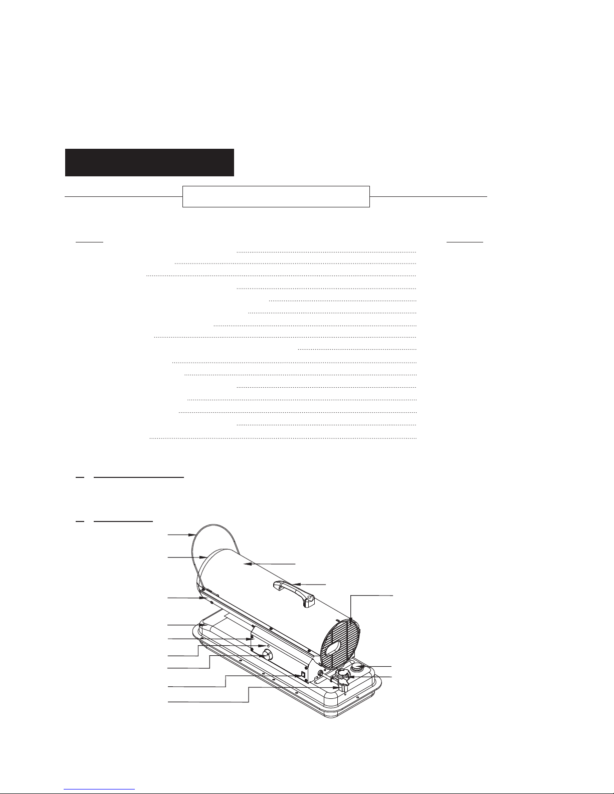
2. FEATURES
CONTENTS OF USER’S MANUAL
Fan Guard
Fuel Gauge
Fuel Cap
Front Guard
Hot Air Outlet
Lower Shell
Fuel Tank
Side Cover
Lamp
Thermostot Knob
(75TDGD Model Only)
Power/Reset Switch
Power Cord
(Piggy Back, 75TDGD Model Only)
Upper Shell
Handle
Figure 1. RMC-KFA50DGD/75TDGD MODELS
3
NEVER LEAVE THE HEATER
UNATTENDED WHILE BURNING!
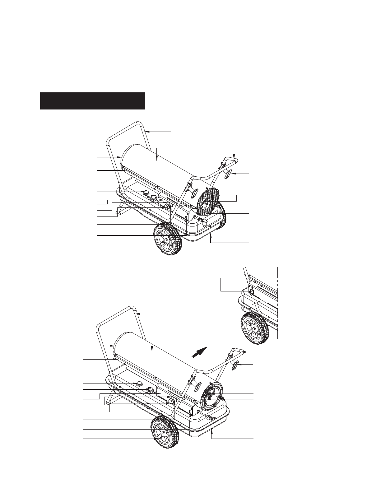
Figure 2. RMC-KFA125/170TDGD-01 MODELS
Figure 3. RMC-KFA210TDGD-01 MODEL
Hot Air Outlet
Shell Lower
Fuel Gauge
Fuel Cap
Side Cover
Lamp
Thermostot Knob
Room Temp. Display
(170TDGD-01 Model Only)
Power/Reset Switch
10” Flat Free Wheel
Hot Air Outlet
Shell Lower
Fuel Gauge
Fuel Cap
Side Cover
Thermostot Knob
Lamp
Room Temp. Display
Power/Reset Switch
10” Flat Free Wheel
Snap Fit Front Handle
Snap Fit Rear Handle
Snap Fit Rear Handle
Upper Shell
Snap Fit Front Handle
Electric Outlet
Upper Shell
Cord Wrap
Cord Wrap
BTU Control Switch
Pressure Gauge
Fan Guard
Power Cord
(Piggy Back)
Fuel Drain Bolt
BTU Control Switch
Pressure Gauge
Fan Guard
Power Cord
Fuel Drain Bolt
4
NEVER LEAVE THE HEATER
UNATTENDED WHILE BURNING!
Figure 5. RMC-KFA125/170/210TDGD-01 MODELS
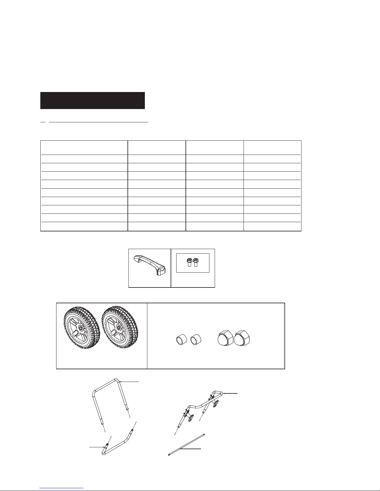
3. UNPACKING AND ASSEMBLY
1. REMOVE THE HEATER AND ALL PACKING MATERIALS FROM THE BOX. (Fig. 4 and 5)
NOTE : Save the shipping carton and packing materials for future storage.
Figure 4. RMC-KFA50DGD/75TDGD MODELS
RMC-KFA50DGD
RMC-KFA75TDGD
RMC-KFA170TDGD-01
RMC-KFA210TDGD-01
RMC-KFA125TDGD-01
Snap Fit Front Leg No Yes Yes
Wheel No Yes Yes
seYseYoNThreaded Axle
seYseYoNSnap Fit front Handle
Snap Fit Rear Handle
seYseYoN
oNoNseYeldnaH
seYseYseYparW droC
Hardware kit : HW-KFA1000 Yes No No
Hardware kit : HW-KFA1015 No Yes Yes
Wheels
(10” Flat Free)
Bushings Cap Nuts
Hardware Kit : HW-KFA1015
Threaded Axle
Snap Fit Front Leg
Snap Fit Rear Handle
Snap Fit Front Handle
Handle
Hardware Kit
HW-KFA1000
5
NEVER LEAVE THE HEATER
UNATTENDED WHILE BURNING!
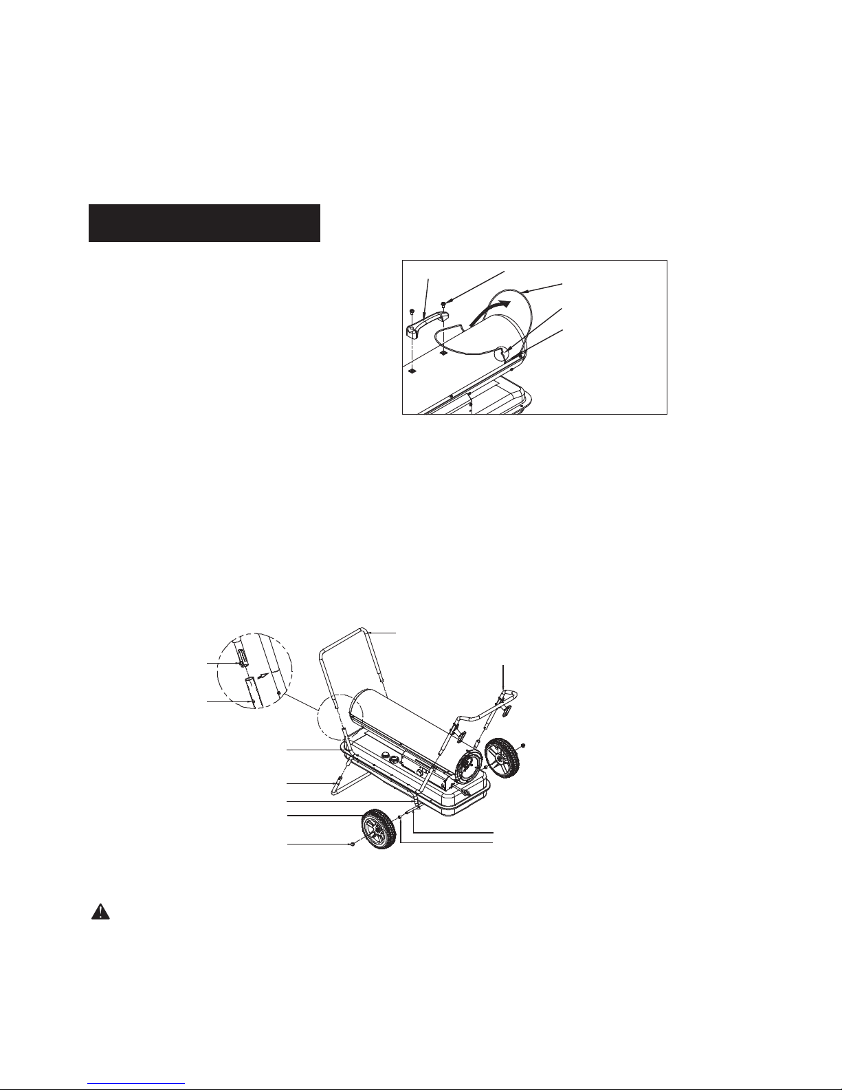
2. ASSEMBLY
For RMC-KFA50DGD/75TDGD Models only
(Assembly time for this product is 3 minutes)
For RMC-KFA125/170/210TDGD-01 Models only (Assembly time for this product is 10 minutes)
Tools Required
• Medium Phillips Screwdriver.
1) Lift front guard for arrow direction and make
sure that guard’s wedged portion fits into the slit
hole on the upper housing.
2) Align the holes in the upper housing with two
mounting holes on the handle as shown in Figure 6.
3) Secure handle with Screws with provided.
Tools Required
• 3/4 inch Socket or Adjustable Wrench
1) Align and insert snapfit front leg in to the front section of the bottom leg and wheel support. You will need
to depress the metal buttons when installing. See Figure 7 below.
2) Slide threaded axle through the rear sectioon of the bottom leg and wheel support.
3) Slide one axle bushing on to each side of the axle. Slide one wheel on to each side of the axle. Attach one
cap nut on to each side of the threaded axle and tighten well.
4) Align and insert snapfit front and rear handles to the top support handle. You will need to depress the metal
buttons on each handle when installing. See Figure 7 below.
Figure 7. Assembling Handles & Wheels
CAUTION : DO NOT OPERATE heater without support frame assembled to tank.
NOTE : Heater should be inspected before each use, and at least annually by a qualified service person.
Button
Hole
Snap Fit Front Handle
Snap Fit Rear Handle
Cap Nut
Wheel
Bottom Leg And Wheel Support
Snap Fit Front Leg
Top Handle Support
Threaded Axle
Bushing
Figure 6. Assembling Handle
Handle
Screw
Front Guard
Slit Hole
Wedged Portion

6
NEVER LEAVE THE HEATER
UNATTENDED WHILE BURNING!
4. KEROSENE (1-K)
For optimal performance of this heater, it is strongly suggested that 1-K kerosene be used. 1-K kerosene has
been refined to virtually eliminate contaminants, such as sulpher. Which can cause a rotten egg odor during
the operation of the heater. However, #1 diesel/fuel oil may also be used if 1-K kerosene is not available.
Be advised that these fuels do not burn as clean as 1-K kerosene, and care should be taken to provide more
fresh air ventilation to accomodate any added contaminants that may be added to the heated space.
KEROSENE SHOULD ONLY BE STORED IN A BLUE CONTAINER THAT IS CLEARLY
MARKED “KEROSENE”. NEVER STORE KEROSENE IN A RED CONTAINER.
Red containers are associated with gasoline.
NEVER
store kerosene in the living space. Kerosene should be stored in a well ventilated place outside the
living area.
NEVER use any fuel other than 1-K kerosene (#1 diesel and #1 oil are acceptable substitutes)
NEVER use fuel such as gasoline, benzene, alcohol, white gas, camp stove fuel, paint thinners, or other oil
compounds in this heater. These are volatile fuels that can cause an explosion or uncontrolled flames.
NEVER store kerosene in direct sunlight or near a source of heat.
NEVER use kerosene that has been stored from one season to the next. Kerosene deteriorates over time.
“OLD KEROSENE” WILL NOT BURN PROPERLY IN THIS HEATER.
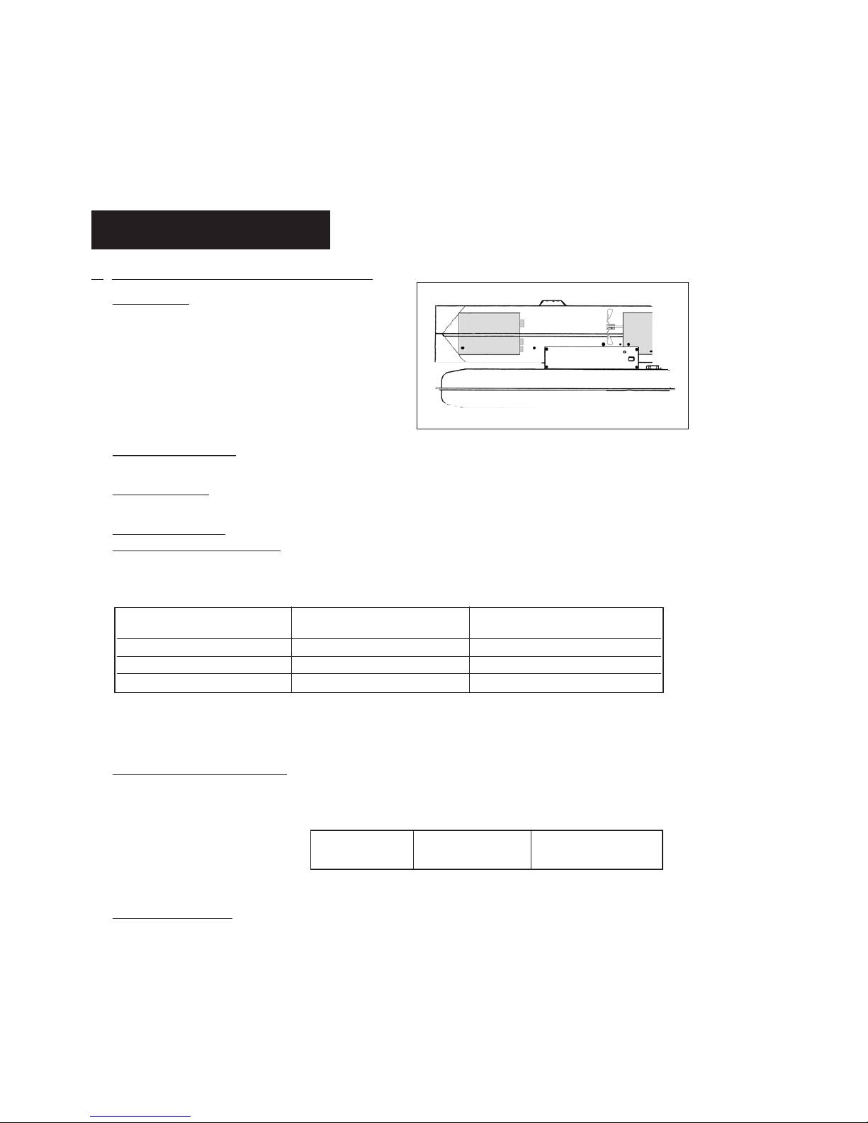
5. OVERVIEW OF HEATERS DESIGN
Fuel System : This heater is equipped with an electric
air pump that forces air through the air
line connected to the fuel intake and then
through a nozzle in the burner head.
When the air passes in front of the fuel
intake it causes fuel to rise from the tank
and into the burner nozzle. This fuel and
air mixture is then sprayed into the
combustion chamber in a fine mist.
“Sure Fire Ignition” : The electronic ignitor sends voltage to a specially designed spark plug.
The spark plug ignites the fuel and air mixture described above.
The Air System :
The heavy duty motor turns a fan that forces air into and around the combustion chamber.
Here the air is heated and then forced out the front of the heater.
The Safety System :
A. Temperature Limit Control : This heater is equipped with a Temperature Limit Control designed to turn
off the heater should the internal temperature rise to an unsafe level. If this
device activates and turns your heater off it may require service.
Once the temperature falls below the reset temperature you will be able to start your heater.
B. Electrical System Protection : This heaters electrical system is protected by a fuse mounted to the PCB
assembly that protects it and other electrical components from damage.
If your heater fails to operate check this fuse first and replace as needed.
C. Flame-Out Sensor : Utilizes a photocell to monitor the flame in burn chamber during normal operation.
It will cause the heater to shut-off should the burner flame extinguish.
7
NEVER LEAVE THE HEATER
UNATTENDED WHILE BURNING!
Internal Shut-Off Temp. Reset Temperature
MODELS
Plus/Minus 10 Degrees Plus/Minus 10 Degrees
RMC-KFA50DGD/75TDGD
176˚F/80˚C 122˚F/50˚C
RMC-KFA125/170TDGD-01
230˚F/110˚C 194˚F/90˚C
RMC-KFA210TDGD-01
194˚F/90˚C 140˚F/60˚C
FUSE TYPE: All Models 125 volt / 8 amps
6. FUELING YOUR HEATER
NEVER FILL THE HEATER FUEL TANK IN THE LIVING SPACE : FILL THE TANK OUTDOORS.
DO NOT OVERFILL YOUR HEATER AND BE SURE HEATER IS LEVELED.
IMPORTANT NOTICE REGARDING FIRST IGNITION OF HEATER :
The first time you light the heater, it should be done outdoors. This allows the oils, etc. used in
manufacturing the heater to burn off outside.
WARNING!! : NEVER REFILL HEATER FUEL TANK WHEN HEATER IS OPERATING OR STILL HOT.
7. OPERATION
A.) VENTILATION
RISK OF INDOOR AIR POLLUTION/USE HEATER ONLY IN WELL VENTILATED AREAS.
Provide a fresh air opening of at least three square feet (2,800 sq. cm) for each 100,000 BTU/Hr.
rating. Provide extra fresh air if more heaters are being used.
Example : A RMC-KFA210TDGD-01 heater requires one of the following:
• a two-car garage door raised six inches (15.24 cm)
• a single-car garage door raised nine inches (22.86 cm)
• two, thirty-inch (76.20 cm) windows raised fifteen inches (38.1 cm)
B.) OPERATION
TO START HEATER
1. Fill fuel tank with kerosene or No. 1 fuel oil.
2. Attach fuel cap.
3. Plug power cord of heater into three-prong, grounded extension cord. Extension cord must be at
least six feet long.
Extension Cord Wire Size Requirements
• 6 to 10 feet (1.8 to 3 meters) long, use 18 AWG conductor.
• 11 to 100 feet (3.4 to 30.5 meters) long, use 16 AWG conductor.
• 101 to 200 feet (30.8 to 61 meters) long, use 14 AWG conductor.
4. Turn “THERMOSTAT CONTROL knob” to desired setting (setting range : 40˚F ~ 110˚F)
(RMC-KFA75TDGD/RMC-KFA125/170/210TDGD-01 Models Only)
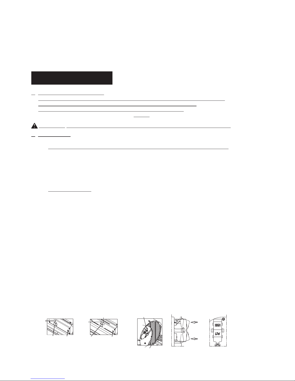
5. Push “BTU control Switch” to desired level “High or LOW” (See Figure 8.)
(RMC-KFA125/170/210TDGD-01 Models Only)
6. Push Power Switch to “ON” position, Power lndicator Lamp will light and heater will start.
NOTE : Room Temperature display explanations are as follows: (RMC-KFA170/210TDGD-01 Models only)
• When the room temperature is less 0℉, the LED display will show “Lo”
When room temp is between 0℉ and 99℉, the number shown on the display is the current
room temperature.
When room temperature is greater than 99℉, the LED display will show “Hi”
•
•
If heater does not start, the thermostat setting may be too low, turn “thermostat Control Knob” to
higher position to start heater. If heater still does not start, turn power switch to “OFF” and then to
“ON” position. If heater still does not start, see Troubleshootiong Guide on page15.
NOTE : User can Select to operate the heater on two different BTU levels(High or Low). The BTU level can
be selected before turning the unit on, or while it is in operation by pushing the BTU control switch.
8
NEVER LEAVE THE HEATER
UNATTENDED WHILE BURNING!
Figure 8. Controls for All Models
Power/Reset
Switch
RMC-KFA50DGD/75TDGD/
125TDGD-01 Models
RMC-KFA170/210TDGD-01 Models
Room Temp. Display
Power/Reset
Switch
Thermostat
Control Knob
(75TDGD/125TDGD-01 MODELS ONLY)
Thermostat
Control Knob
Lamp
Lamp
BTU Control Switch
BTU Control Switch
Fan Guard
Push to “HIGH”
Push to “LOW”
 Loading...