

Dyna-Glo BF10DTDG-4, BF20DTDG-4, BF30DTDG-4, GBF30DTDG-4 User Manual
WARNING: This appliance is equipped for
Natural and Propane gas. Field conversion is
not permitted.
VENT-FREE
BLUE FLAME
GAS WALL HEATER
MODEL #BF10DTDG-4
BF20DTDG-4
BF30DTDG-4
GBF30DTDG-4
WARNING: Do not attempt to access or change
the setting of the fuel selection means.
Access to and adjustment of the fuel selection means
must only be performed by a qualied service person
when connecting this appliance to a specied fuel
supply at the time of installation.
Change of the selector setting to other than the fuel type
specied at the time of installation could damage this
appliance and render it inoperable.
The installer shall replace the access cover before
completing the installation and operating this appliance.
Gas Fired Room Heaters
Volume II - Unvented Room Heaters
Patent Pending Dual
Fuel System
ANS Z21.11.2-2016
WARNING: IF THE INFORMATION IN THIS MANUAL IS NOT FOLLOWED
EXACTLY, A FIRE OR EXPLOSION MAY RESULT CAUSING PROPERTY
DAMAGE, PERSONAL INJURY OR LOSS OF LIFE.
- Do not store or use gasoline or other ammable vapors and Iiquids in vicinity of this or
any other appliance.
WHAT TO DO IF YOU SMELL GAS
• Do not try to light any appliance.
• Do not touch any electrical switch; do not use any phone in your building.
• Immediately call your gas supplier from a neighbor’s phone. Follow the gas supplier’s
instructions.
• If you cannot reach your gas supplier, call the re department.
- Installation and service must be performed by a qualied installer, service agency or the
gas supplier.
This is an unvented gas-red heater. It uses air (oxygen) from the room in which it is
installed. Provisions for adequate combustion and ventilation air must be provided.
Refer to Air For Combustion and Ventilation section on page 8 of this manual.
INSTALLER: Leave this manual with the appliance.
CONSUMER: Retain this manual for future reference.
This appliance may be installed in an aftermarket, permanently located, manufactured (mobile)
home, where not prohibited by local codes.
This appliance is only for use with propane or natural gas.
This appliance is equipped with a simple means to switch between propane and natural gas.
Field conversion by any other means including the use of a kit is not permitted.
Questions, problems, missing parts? Before returning to your retailer, call our customer
service department at 1-877-447-4768, 8:30 a.m. – 4:30 p.m., CST, Monday – Friday or
email us at customerservice@ghpgroupinc.com.
1
IMDFBFG4 - 2019-03-25

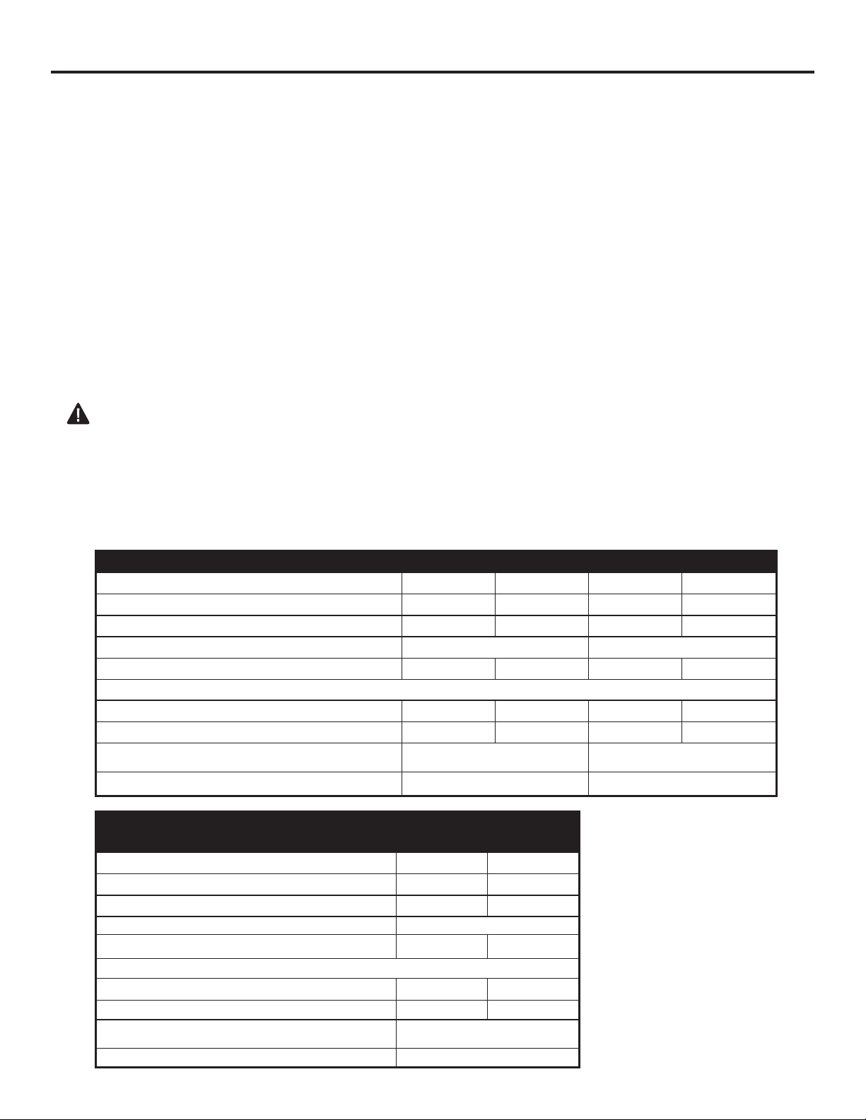
TABLE OF CONTENTS
Important Safety Information ............................................................................................................3
Product Features .............................................................................................................................. 5
Air For Combustion and Ventilation .................................................................................................. 7
Installation ......................................................................................................................................10
Gas Conversion .............................................................................................................................. 11
Operation ........................................................................................................................................18
Care and Maintenance ................................................................................................................... 22
Troubleshooting .............................................................................................................................. 23
Replacement Parts ......................................................................................................................... 27
Warranty ......................................................................................................................................... 28
WARNING: Read the Installation & Operating Instructions before using this appliance.
IMPORTANT: Read all instructions and warnings carefully before starting installation.
Failure to follow these instructions may result in possible injury to persons or a re
hazard and will void the warranty.
PRODUCT SPECIFICATIONS
SERIES BF10DTDG-4 BF20DTDG-4
MAX BTU
MIN BTU
Fuel Type
Ignition
Manifold Pressure
Inlet Gas Pressure
Maximum
*Mínimum (*For purposes of input adjustment)
Dimensiones (in.)
(H x W x D)
Fan Ratings (Select Models)
SERIES
MAX BTU
MIN BTU
Fuel Type
Ignition
Manifold Pressure
Inlet Gas Pressure
Maximum
*Mínimum (*For purposes of input adjustment)
Dimensiones (in.)
(H x W x D)
Fan Ratings (Select Models)
10,000 10,000 20,000 20,000
5,000 8,000 10,000 16,000
Natural Gas Propane Natural Gas Propane
Electronic Push Button Electronic Push Button
5 in. W.C. 10 in. W.C. 5 in. W.C. 10 in. W.C.
14 in. W.C. 14 in.W.C. 14 in. W.C. 14 in. W.C.
6 in. W.C. 11 in. W.C. 6 in. W.C. 11 in. W.C.
20.00 in. x 17.32 in. x 9.49 in. 242.0 in. x 20.94 in. X 10.08 in.
120V/60Hz, 18W, 0.15A 120V/60Hz, 18W, 0.15A
BF30DTDG-4
GBF30DTDG-4
30,000 30,000
15,000 24,000
Natural Gas Propane
Electronic Push Button
5 in. W.C. 10 in. W.C.
14 in. W.C. 14 in.W.C.
6 in. W.C. 11 in. W.C.
24.09 in. x 28.07 in. x 10.51 in.
120V/60Hz, 18W, 0.15A
2
IMPORTANT SAFETY INFORMATION
IMPORTANT: Read this owner’s manual carefully and completely before trying to assemble, operate,
or service this heater. Improper use of this heater can cause serious injury or death from burns, re,
explosion, electrical shock, and carbon monoxide poisoning.
WARNING: FIRE, EXPLOSION, AND ASPHYXIATION HAZARD
Improper adjustment, alteration, service, maintenance, or installation of this heater or its controls can cause
death or serious injury.
Read and follow instructions and precautions in User’s Information Manual provided with this heater.
Installation and repair should be done by a qualied service person. The appliance should be
inspected before use and at least annually by a professional service person. More frequent
cleaning may be required due to excessive lint from carpeting, bedding material, etc. It
is imperative that control compartments, burners and circulating air passageways of the
appliance be kept clean.
WARNING: Any change to this heater or its controls can be dangerous.
WARNING: Carefully supervise young children when they are in the room with the heater.
WARNING: Heater becomes very hot when operating. Children and adults should be alerted
to the hazard of high surface temperatures and should stay away to avoid burns or clothing
ignition Heater will remain hot for a time after shutoff. Allow surfaces to cool before touching.
WARNING: Make sure any panel, safety screen or guard removed for servicing an appliance
is replaced prior to operating the heater
WARNING: Keep the appliance area clear and free from combustible materials, gasoline, and
other ammable vapors and liquids.
WARNING: Do not place clothing or other ammable material on or near the appliance. Never
place any objects on the heater.
WARNING: Due to high temperatures, locate this appliance out of trafc and away from
furniture and draperies.
This appliance is intended for supplemental heating.
This appliance can be used with propane or natural gas. It is shipped from the factory adjusted for
use with propane.
CARBON MONOXIDE POISONING: Early signs of carbon monoxide poisoning resemble the u with
headaches, dizziness, or nausea. If you have these signs, the heater may not be working properly. Get
fresh air immediately! Have heater serviced. Some people are more affected by carbon monoxide than
others. These include pregnant women, people with heart or lung disease, people who are
anemic, those under the inuence of alcohol, and those living in high altitudes.
NATURAL AND PROPANE/LP GAS: Natural and Propane/LP gases are odorless. An odor-making
agent is added to the gas. The odor helps you detect a gas leak. However, the odor added to the gas
can fade. Gas may be present even though no odor exists. Make certain you read and understand all
warnings. Keep this manual for reference. It is your guide to operating this heater safely.
WARNING:
If the heater is being installed in a residential garage, it must be secured rmly to the
wall, a minimum of 18 in. (457mm) above the oor. The heater must be located so that it
is protected against any possibility of damage by a moving vehicle, etc.
Raising the heater will reduce BUT NOT eliminate the possibility of lighting the vapor of any
ammable liquids which may be improperly stored or accidentally spilled. If the smell of
gasoline is present, do not operate this heater until the area has been properly ventilated.
3
SAFETY INFORMATION
WARNING: Do not use any accessories not approved for use with this heater.
WARNING
This product and the fuels used to operate this product (liquid propane or natural gas), and the
products of combustion of such fuels, can expose you to chemicals including benzene, which is
known to the State of California to cause cancer and reproductive harm.
For more information go to www.p65Warnings.ca.gov
1. Do not place Propane/LP supply tank(s) inside any structure. Place Propane/LP supply tank(s)
outdoors.
2. Only the BF10 Series can be installed in a bedroom. When installing in a bedroom the heater
MUST be mounted to the wall (See Wall Mounting, Page 13). All other models cannot be installed
in a bedroom. These units are not approved for bathroom use.
3. This heater needs fresh air ventilation to run properly. This heater has an Oxygen Depletion Sensing
(ODS) safety shutoff system. The ODS shuts down the heater if not enough fresh air is available.
See Air for Combustion and Ventilation, pages 7 through 9. If heater keeps shutting off, see
Troubleshooting, pages 23 through 26.
4. Keep all air openings in front, top and bottom of heater free of objects and debris to ensure
adequate air for proper combustion.
5. If heater shuts off, do not relight until you have provided fresh, outside air. If heater keeps shutting
off, have it serviced.
6. Do not run heater:
• Where ammable liquids or vapors are used or stored.
• Under dusty conditions.
7. Before using furniture polish, wax, carpet cleaner, or similar products, turn heater and pilot off. If
heated, the vapors from these products may create a white powder residue within burner box or
on adjacent walls or furniture.
8. Do not use heater if any part has been under water. Immediately call a qualied service technician
to inspect the room heater and to replace any part of the control system and any gas control which
has been under water.
9. Turn off and unplug heater and let cool before servicing. Only a qualied service person should
service and repair heater.
10. To prevent performance problems, do not use propane/LP fuel tank of less than 100 lbs. capacity.
11. WARNING: Do not allow fans to blow directly into the heater. Avoid any drafts that alter
burner ame patterns.
12. SAVE THESE INSTRUCTIONS.
4
PRODUCT FEATURES
SAFETY PILOT
This heater has a pilot with an Oxygen Depletion Sensing (ODS) safety shutoff system.
The ODS/pilot shuts off the heater if there is not enough fresh air and cuts off main burner gas in the
event of ame out.
DUAL FUEL CAPABILITY
Your heater is equipped to operate on either propane or natural gas. The heater is
shipped from the factory ready for connecting to propane. The heater can easily be
changed to natural gas by having your qualied installer follow the instructions on page
11 and the markings on the heater.
LEG KIT(SELECT MODELS)
2 support legs and 4 support leg screws are included for oor mounting the heater. See page 13.
NOTE: This is an optional accessory and is not required for operation of the heater.
ELECTRONIC PUSH BUTTON IGNITION SYSTEM
This heater is equipped with an electronic push button ignition system. This system requires
one AAA battery (provided).
THERMOSTAT HEAT CONTROL(SELECT MODELS)
The control automatically cycles the burner on and off to maintain a desired room
temperature. See page 24.
FAN KIT(SELECT MODELS)
The fan kit helps to distribute the warmed air into the space more rapidly.
NOTE: This is an optional accessory and is not required for operation of the heater.
State of Massachusetts: The installation must be made by a licensed plumber or gas tter in
the Commonwealth of Massachusetts. Sellers of unvented propane or natural gas-red
supplemental room heaters shall provide to each purchaser a copy of 527 CMR 30 upon sale
of the unit.
In the State of Massachusetts, unvented propane or natural gas-red space heaters shall be
prohibited in bedrooms and bathrooms.
In the State of Massachusetts the gas cock must be a T-handle type. The State of
Massachusetts requires that a exible appliance connector cannot exceed three feet in
length.
LOCAL CODES
Install and use heater with care. The installation must conform with local codes or, in the absence of
local codes, with the latest edition of The Nation Fuel Gas Code, ANS Z223.1/NFPA 54
*Available from:
American National Standard Institute, Inc. National Fire Protection Association, Inc.
1430 Broadway 1 Batterymarch Park
New York, NY 10018 Quincy, MA 02269-9101
This heater is designed for vent-free operation. State and local codes in some areas prohibit, restrict
and or have special requirements for vent-free heaters.
5
PREPARING FOR INSTALLATION
Before beginning assembly or operation of the product, make sure all parts are present.
Compare parts with package contents list. If any part is missing or damaged, do not attempt
to assemble, install or operate the product. Contact customer service for replacement parts.
UNPACKING
1. Remove heater from carton.
2. Remove all protective packaging applied to heater for shipping
3. Verify all contents are present.
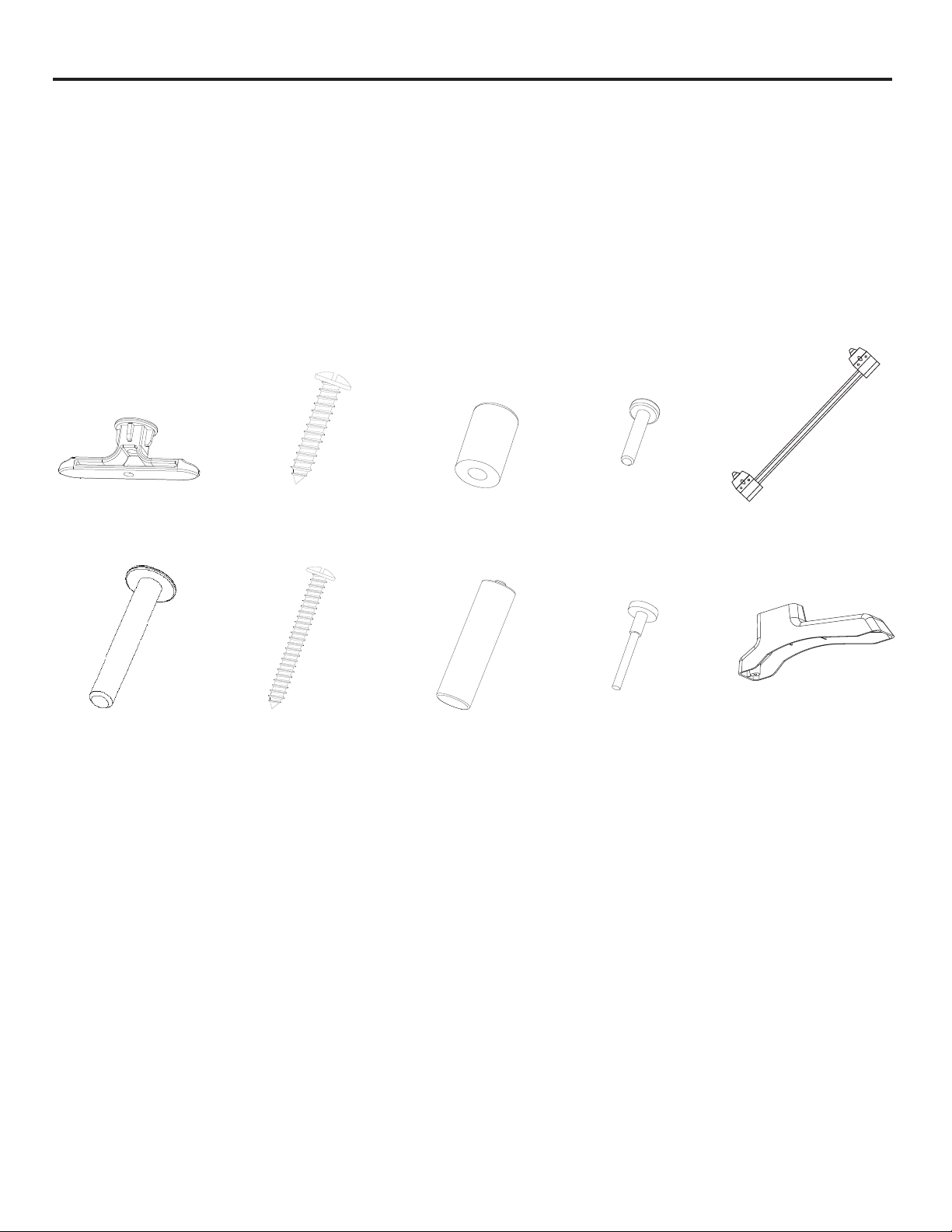
NOTE: Support Leg Screw (M4*15) (Select Models), Wood Screw (ST4.8*45-16),
Expansion Bracket Screw (ST4.8*15-16), and Expansion Bracket come with (2) extra each.
expansion
Bracket x 4
Wall Hanging
Spacer Screw
(M4*25) x 2
4. Check heater for any shipping damage. If heater is damaged, promptly inform dealer where you
bought the heater.
WATER VAPOR: A BY-PRODUCT OF UNVENTED ROOM HEATERS
Water vapor is a by-product of gas combustion. An unvented room heater produces
approximately one (1) ounce (30 mL) of water for every 1,000 BTUs (0.3 Kw) of gas input
per hour. An unvented room heater is intended as a supplemental heater rather than a primary heat
source. In most supplemental heat applications, the water vapor does not create a problem.
In most applications, the water vapor enhances the low humidity atmosphere experienced during
cold weather.
The following steps will help ensure that water vapor does not become a problem:
1. Be sure the heater is the proper size for the application, including adequate combustion air and
circulation air.
2. If there is high humidity, a dehumidier may be used to help lower the water vapor content
of the air.
3. Do not use an unvented room heater as the primary heat source.
expansion Bracket
Screw (ST4.8*15-16) x 4
Wood Screw
(ST4.8*45-16) x 4
Wall Hanging
Spacer x 2
AAA Battery x 1
Support Leg Screw
(M4*15) x 4
(Select Models)
expansion Bracket
Tool x 1
Wall Mounting
Bracket x 1
Support Leg x 2
(Select Models)
6

PREPARING FOR INSTALLATION
AIR FOR COMBUSTION AND VENTILATION
CAUTION: This heater shall not be installed in a room or space unless the required volume
of indoor combustion air is provided by the method described in the National Fuel Gas Code, ANS
Z223.1/NFPA54, the International Fuel Gas Code, or applicable local codes.
PRODUCING ADEQUATE VENTILATION
All spaces in homes fall into one of the three following ventilation classications:
1. Unusually Tight Construction
2. Unconned Space
3. Conned Space
The information on pages 7 through 9 will help you classify your space and provide adequate ventilation.
Conned and Unconned Space
A conned space as a space whose volume is less than 50 cu. ft. per 1,000 BTU/hr (4.8 m^3 per kw)
of the aggregate input rating of all appliances installed in that space and an unconning space as a
space whose volume is not less than 50 cu. ft. per 1,000 BTU/hr (4.8 m^3 per kw) of the aggregate
input rating of all appliances installed in that space. Rooms connecting directly with the space in
which the appliances are installed*, through openings not furnished with doors, are considered a
part of the unconned space.
This heater shall not be installed in a conned space or unusually tight construction unless provisions
are provided for adequate combustion and ventilation air.
* Adjoining rooms are connecting only if there are doorless passageways or ventilation
grills between them.
Unusually Tight Construction
The air that leaks around doors and windows may provide enough fresh air for combustion and ventilation. However, in buildings of unusually tight construction, you must provide additional
fresh air.
Unusually tight construction is dened as construction where:
a) walls and ceilings exposed to the outside atmosphere have a continuous water vapor retarder
with a rating of one perm (6x10-11kg per pa-sec-m2) or less with openings gasketed or sealed
and
b) weather stripping has been added on windows that can be opened and on doors and
c) caulking or sealants are applied to areas such as joints around window and door frames,
between sole plates and oors, between wall-ceiling joints, between wall panels, at
penetrations for plumbing, electrical, and gas lines, and at other openings.
If your home meets all of the three criteria above, you must provide additional fresh air.
See “Ventilation Air From Outdoors” (page 9). If your home does not meet all of the
three criteria above, proceed to “Determining Fresh-Air Flow For Heater Location”.
7

PREPARING FOR INSTALLATION
DETERMINING FRESH-AIR FLOW FOR HEATER LOCATION
Determining if You Have a Conned or Unconned Space
Use this worksheet to determine if you have a conned or unconned space.
Space: Includes the room in which you will install heater plus any adjoining rooms with
doorless passageways or ventilation grills between the rooms.
1. Determine the volume of the space Length × Width × Height = cu. ft. (volume of space)
Example: Space size 20 ft. (length) × 16 ft.(width) × 8 ft. (ceiling height) = 2560 cu. ft. (volume of
space)
If additional ventilation to adjoining room is supplied with grills or openings, add the volume of these
rooms to the total volume of the space.
2. Divide the space volume by 50 cu. ft. to determine the maximum BTU/hr the space can support.
_______ (volume of space) ÷ 50 cu. ft.= (Maximum BTU/hr the space can support)
Example: 2560 cu. ft. (volume of space) ÷ 50 cu. ft. = 51.2 or 51,200 (maximum BTU/hr the space
can support)
3. Add the BTU/hr of all fuel burning appliances in the space.
Vent-free heater _________ BTU/hr
Gas water heater* ________BTU/hr
Gas furnace _____________BTU/hr
Vented gas heater ________BTU/hr Example:
Gas heater logs __________BTU/hr Gas water heater 30,000 BTU/hr
Other gas appliances*+ ____BTU/hr Vent-free heater + 26,000 BTU/hr
Total = ____BTU/hr Total = 56,000 BTU/hr
*Do not include direct-vent gas appliances. Direct-vent draws combustion air from the
outdoors and vents to the outdoors.
4. Compare the maximum BTU/hr the space can support with the actual amount of BTU/hr used.
_______ BTU/hr (maximum the space can support)
_______ BTU/hr (actual amount of BTU/hr used).
Example : 51,200 BTU/hr (maximum the space can support) 56,000 BTU/hr (actual amount of
BTU/hr used)
The space in the above example is a conned space because the actual BTU/hr used is more than
the maximum BTU/hr the space can support.
You must provide additional fresh air. Your options are as follows:
a) Rework worksheet, adding the space of an adjoining room. If the extra space provides an
unconned space, remove door to adjoining room or add ventilation grills between rooms. See
“Ventilation Air From Inside Building,” page 9.
b) Vent room directly to the outdoors. See “Ventilation Air From Outdoors”, page 9.
c) Install a lower BTU/hr heater if lower BTU/hr size makes room unconned. If the actual BTU/hr
used is less than the maximum BTU/hr the space can support, the space is an unconned space.
You will need no additional fresh air ventilation.
8
PREPARING FOR INSTALLATION
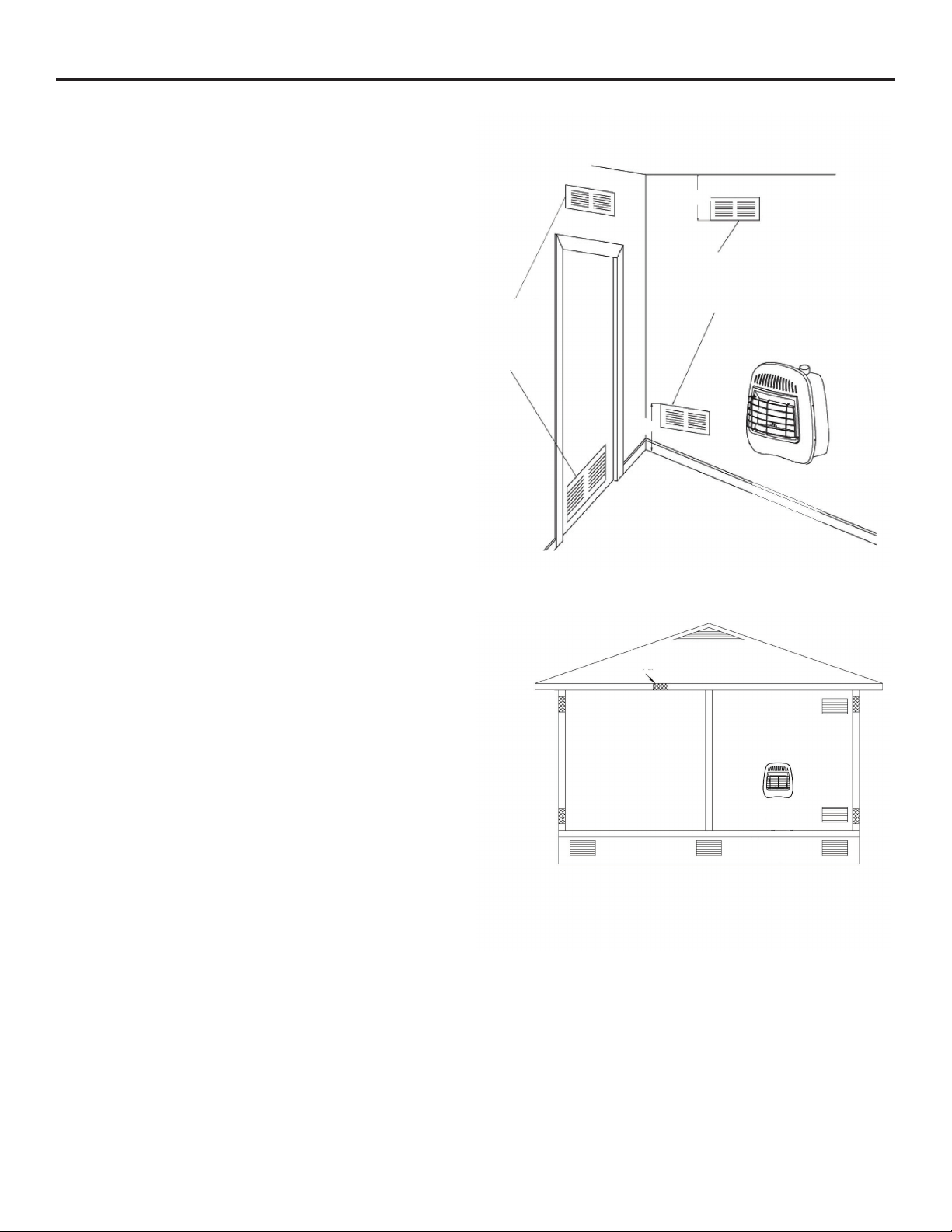
Ventilation Air From Inside Building
This fresh air would come from adjoining
unconned space. When ventilating to an
adjoining unconned space, you must
provide two permanent openings: one
within 12 in. of the wall connecting
the two spaces (see options 1 and 2,
Fig. 1). You can also remove door into
adjoining room (see option 3, Fig. 1).
Follow the National Fuel Gas Code
NFPA 54/ANS Z223.1. Air for Combustion
and Ventilation for required size of
ventilation grills or ducts.
Ventilation Air From Outdoors
Provide extra fresh air by using ventilation
grills or duct. You must provide two
permanent openings: one within 12 in. of
the ceiling and one within 12 in. of the oor.
Connect these items directly to the outdoors
or spaces open to the outdoors. These
spaces include attics and crawl spaces.
Follow the National Fuel Gas Code NFPA
54/ANS Z223.1. Air for Combustion and
Ventilation for required size of ventilation
grills or ducts.
IMPORTANT: Do not provide openings for
inlet or outlet air into attic if attic has a
thermostat-controlled power vent. Heated
air entering the attic will activate the power
vent. Rework worksheet, adding the space
of the adjoining unconned space. The
combined spaces must have enough fresh
air to supply all appliances in both spaces.
Fig. 1 - Ventilation Air from Inside Building
12 in.
Ventilation Grills
Into Adjoining Room,
Option 2
Ventilation
Grills
Into Adjoining
Room,
Option 1
Or
Remove
Door into
Adjoining
Room,
Option 3
12 in.
Fig. 2 - Ventilation Air from Outdoors
Ventilated
Attic
Ventilated
Crawl Space
Outlet
Air
Inlet
Air
Inlet Air
Outlet
Air
To Attic
To Crawl
Space
9
INSTALLATION
NOTICE: This heater is intended for use as supplemental heat. Use this heater along with your
primary heating system. Do not install this heater as your primary heat source.
WARNING: A qualied technician must install heater. Follow all local codes.
WARNING: Maintain the minimum clearances. If possible, provide greater clearances from the
oor, ceiling, and adjoining wall than required.
CAUTION: This heater creates warm air currents. These currents move heat to wall surfaces next
to heater. Installing heater next to vinyl or cloth wall coverings or operating heater where impurities
(such as tobacco smoke, candles, cleaning uids, oil or kerosene lamps, etc.) in the air exist, may
cause walls to discolor.
CLEARANCES TO COMBUSTIBLES
Carefully follow the instructions below. This heater can be mounted on the wall or on the oor
using the support legs (Select models).
WARNING: Maintain the minimum clearances shown in (See Fig. 3). If you can, provide greater
clearances from oor, ceiling, and joining wall.
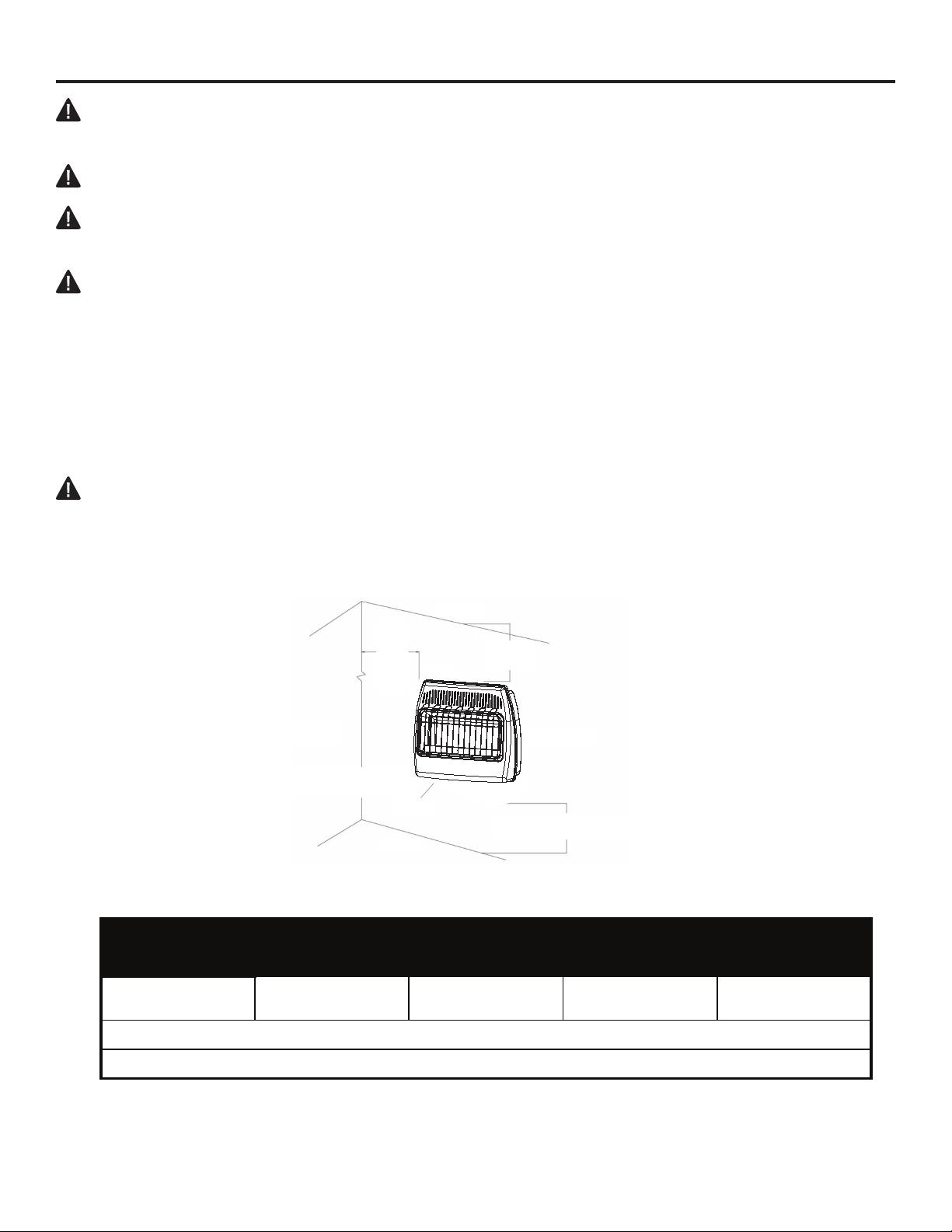
Fig. 3 - Mounting clearances as viewed from
front of heater (inches)
8 in.
Minimum
From
Side of
Heater
LEFT SIDE
36 in. Minimum from
Furniture and Draperies
FLOOR
*A Second Side Wall Must be at Least 18in.
Away from the Other Side of the Heater.
CEILING
36 in.
Minimum
RIGHT SIDE
FRONT
3 in. Minimum to Top Surface of Carpeting,
Tile or Other Combustible Material
MINIMUMCLEARANCETOCOMBUSTIBLES
*LEFT/RIGHT TOP BOTTOM FRONT Rear
8in. 36in. 3in. 36in. 0in.toSpacer
Topclearanceisfromtopofheatertoceiling,woodshelforothercombustiblematerial
Bottomclearanceisfrombottomofheatertosurfaceofcarpet,tileorothercombustiblematerial.
*A second side wall must be at least 18 in. away from the other side of the heater.
Always maintain a minimum of 36 in. clearance from furniture and draperies.
*For the installation in residential garages please refer to the bottom of page 3.
10
INSTALLATION
GAS SELECTION
CAUTION: The knob to the gas selection means shall not be accessed or adjusted while the
appliance is in operation.
WARNING: Gas selection should only be done by a qualied technician.
WARNING: The unused regulator must be tted with a metal plug with a pipe thread sealant.
WARNING: Failure to plug the unused regulator may result in a re, property damage, personal
injury, or death.
Units to be used with LP
Remove the plug from the inlet of the LP regulator; do not make any further adjustments. Proceed to
installing the gas line as instructed in the Owner’s Manual.
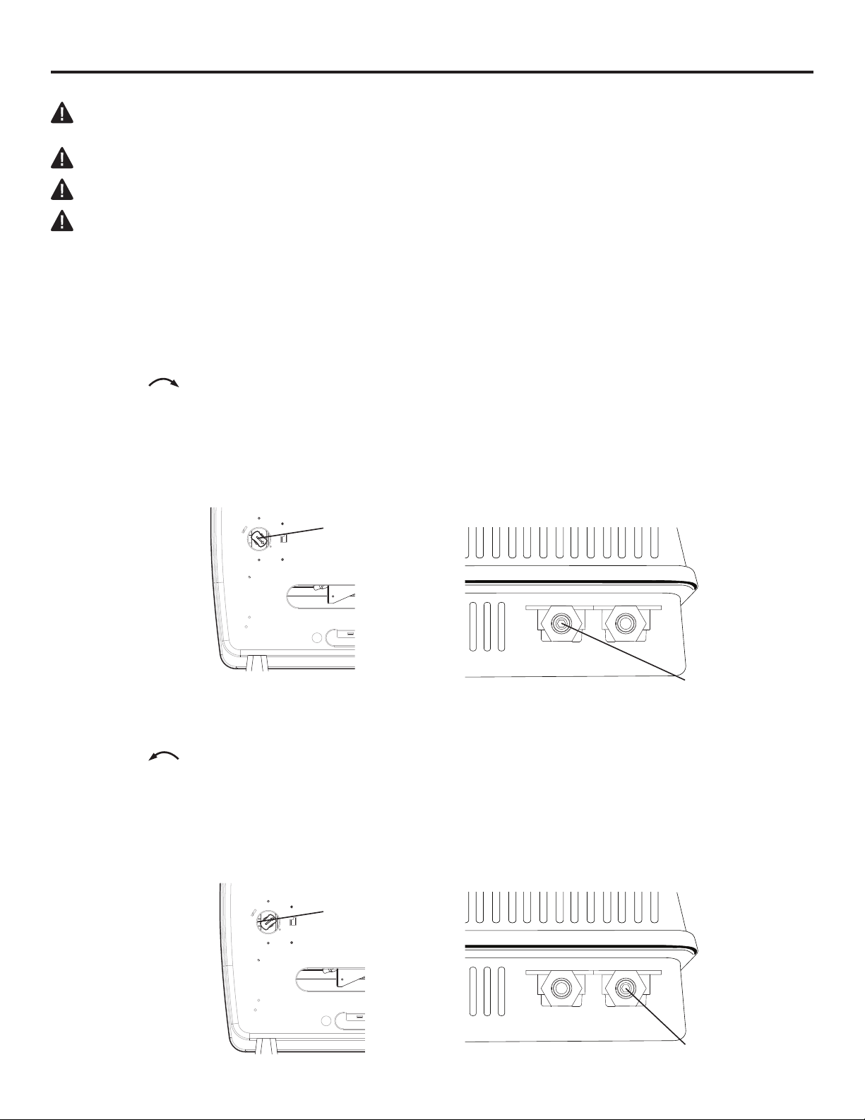
LP TO NG Conversion
1. Before gas conversion, remove screws and access panel for selector valve.
2. The gas selector valve should be in the LP position. Push and turn the selector knob
clockwise until the knob locks into the NG position (See Fig. 4a). The selector valve must
be locked in the NG position. DO NOT operate the heater between the locked positions.
3. Remove plug from the inlet of the NG regulator.
4. If the LP plug was removed previously, apply thread sealant to ensure that there are no leaks
and install the NG plug into the inlet of the LP regulator and tighten rmly. (See Fig 5a and 5b).
5. Replace selector valve access panel.
Fig. 4a - Selector Valve Positioning Fig. 5a - Regulator Plug Location
LP
NG
Selector
Valve
Propane
Natural
Gas
Plug This
NG TO LP CONVERSION
1. Before gas conversion, remove screws and access panel for selector valve.
2. The gas selector valve should be in the NG position. Push and turn the selector knob counter
clockwise until the knob locks into the LP position (See Fig. 4b). The selector valve
must be locked in the LP position. DO NOT operate the heater between the locked positions.
3. Remove plug from the inlet of the LP regulator.
4. Using thread sealant to ensure there are no leaks, replace plug into the inlet of the NG regulator
and tighten rmly (See Fig. 5b).
5. Replace selector valve access panel.
Fig. 4b - Selector Valve Positioning Fig. 5b - Regulator Plug Location
LP
NG
Selector
Valve
11
Propane
Natural
Gas
Plug This
INSTALLATION
INSTALLATION
GAS SELECTION
Fig. 6 - Checking Manifold
Pressure
IMPORTANT: Before proceeding with the installation, the qualied service technician converting the heater between gas supplies must verify
correct manifold pressure. A reading can be taken using a pressure
gauge and the appropriate pressure tap (See Fig. 6).
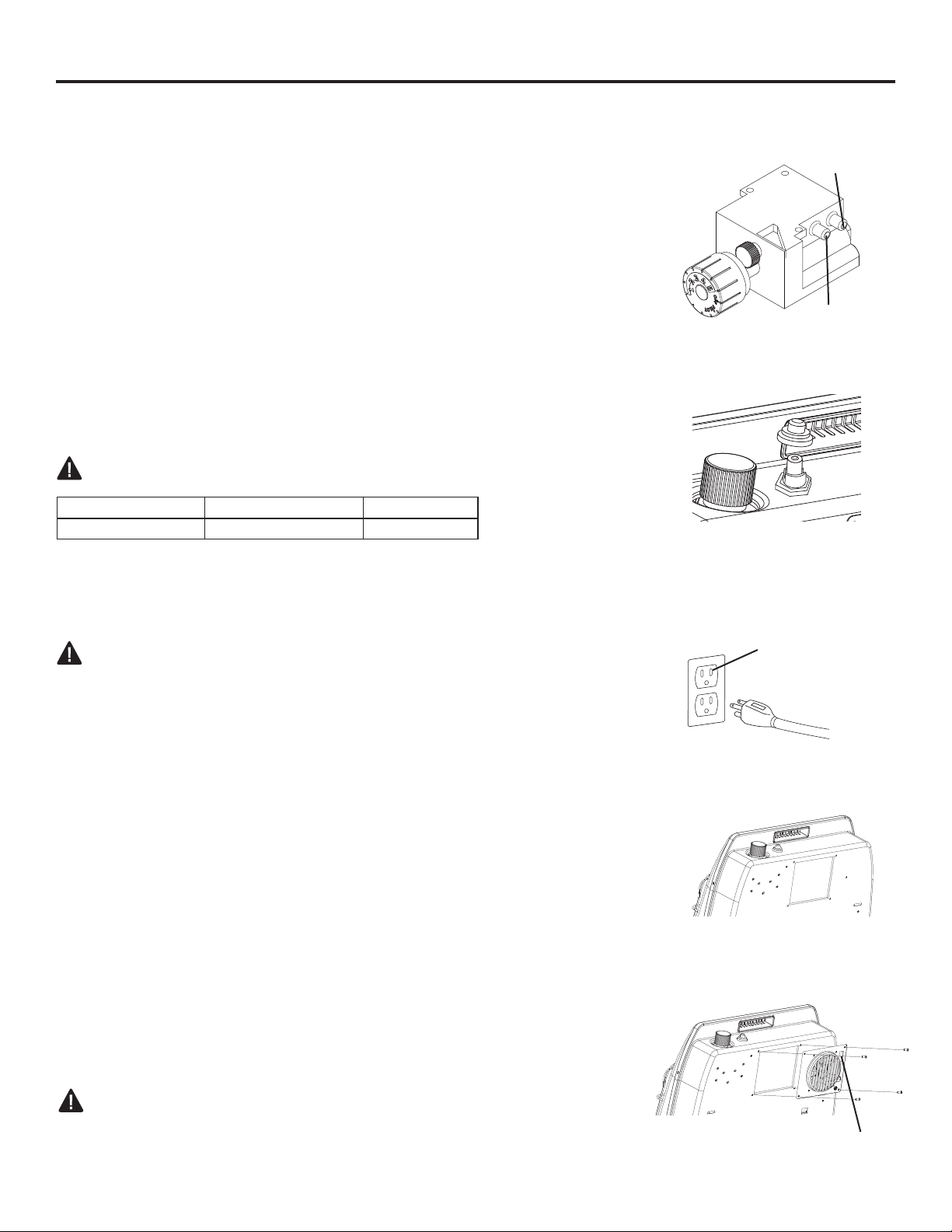
INSTALLING IGNITOR BATTERY
• Battery is included.
• Unscrew ignitor cap and insert included battery negative (at)
side down (See Fig. 7). Replace Ignitor cap.
• Be sure to observe proper polarity (+/-) when installing or re placing the battery. Damage due to improper battery installa tion may void the warranty on the product.
• Install/replace the battery according to the type and quantity
stated in table below.
• Remove battery when depleted.
• For long periods of non-operation, remove the battery from all
components for safety.
WARNING: Do not use rechargable silver oxide cell batteries.
Component Type of Battery Battery Qty.
Ignitor AAA 1
Do NOT dispose of batteries in re. Improper disposal may
cause batteries to leak or explode.
INLET
OUTLET
Fig. 7 - Installing Ignitor Battery
Fig. 8 - Fan Electric Supply
INSTALLING FAN(OPTIONAL)
WARNING: Electrical Grounding Instructions
This appliance is equipped with a three-prong (grounding) plug
for your protection against shock hazard and should be plugged
directly into a properly grounded three-prong receptacle (See Fig. 8).
1. Wall mounted heater must be disconnected from gas supply and
removed from wall before installing fan accessory. Contact a
qualied service person to do this.
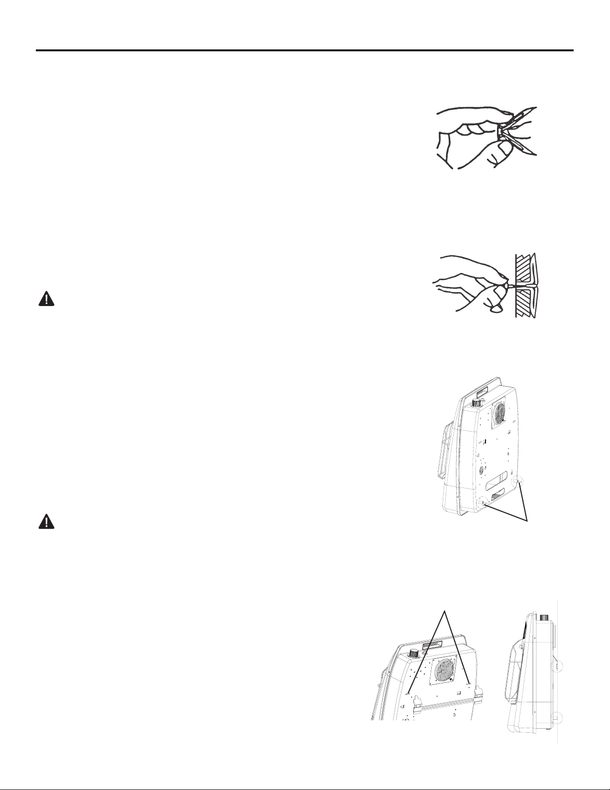
2. Remove fan knock-out panel using a screwdriver (See Fig. 9).
Attach Fan to the rear panel of the heater using the four
screws provided.
NOTE: Be sure the rocker switch is positioned in the upper right
corner. (See Fig. 10).
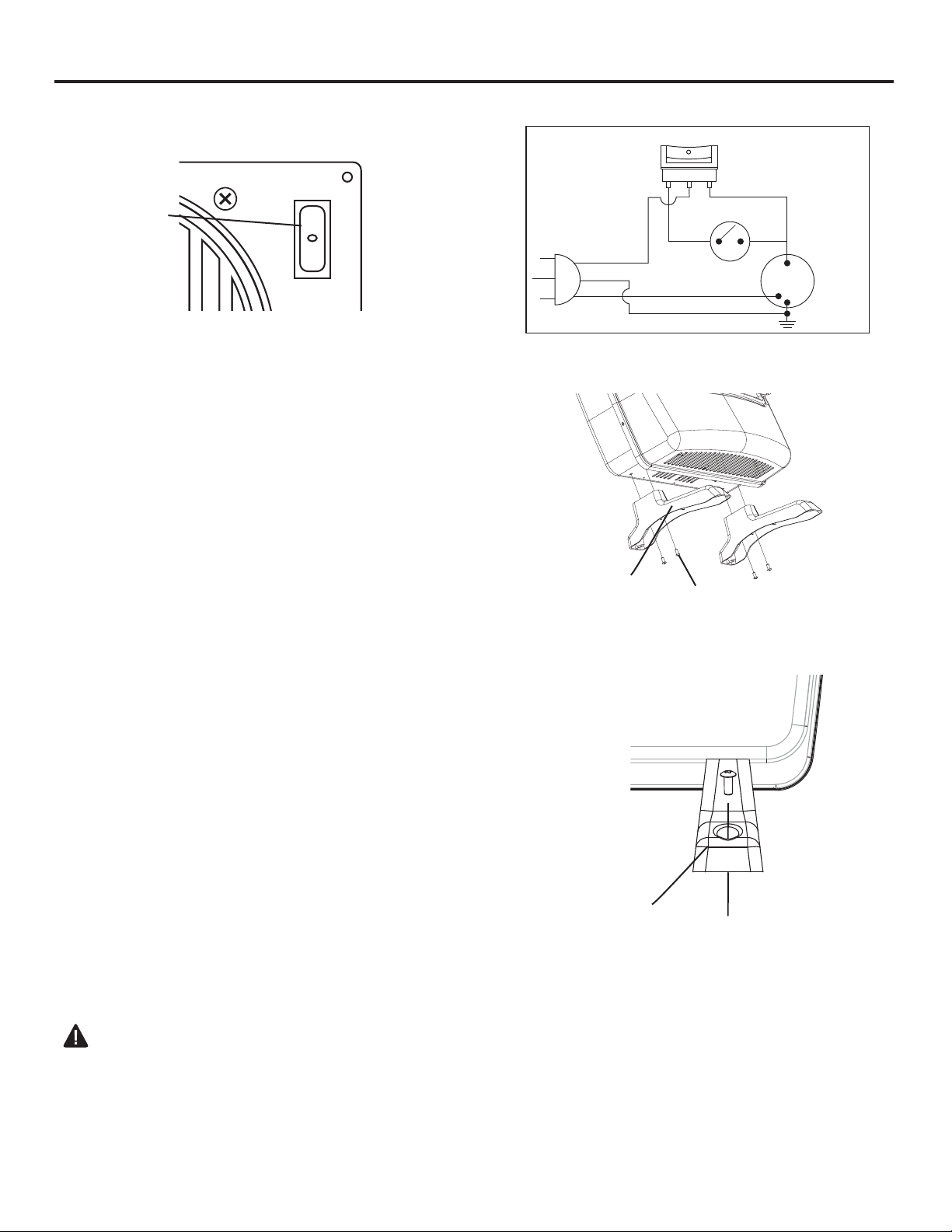
3. This fan is equipped with manual “MAN” and automatic “AUTO”
settings (See Fig. 11 on page 13). Set the rocker switch to “MAN”
for manual mode, allowing the fan to continuously run until the
rocker switch is returned to the OFF “O” position. Set the rocker
switch to “AUTO” for the automatic mode, which will turn the fan on
and off based on ambient room temperature. It may take 5 to 10
minutes for the fan to come on when the unit is cold.
NOTE: If any of the original wire as supplied with the appliance must
be replaced, it must be replaced with a wire of at least an equal temperature rating. Refer to Fig. 12 on page 13 for wiring diagram.
Grounded Three-Prong
Receptacle
Fig. 9 - Knock-out Panel
Fig. 10 - Attaching Fan
CAUTION: Label all wires prior to disconnection when servicing
controls. Wiring errors can cause improper and dangerous opera-
tion. Verify proper operation after servicing.
12
Rocker Switch
INSTALLATION
Fig. 11 - Operating Fan
Fig. 12- Fan Wiring Diagram
Fan Switch
MAN AUTO
Fan Rocker
MAN AUTO
Switch
LOCATING HEATER
This heater is designed to be mounted on a wall or on
a oor, using the Support Legs (Select Models) included with select models.
For convenience and efciency, install heater:
1. Where there is easy access for operation,
inspection, and service.
2. In the coldest part of room.
3. A minimum of 3' away from furniture and draperies.
FLOOR MOUNTING (SELECT MODELS)
(Cannot be done in bedroom or bathroom)
(Cannot be used for garage and ice-house heaters)
NOTE: This is an optional accessory and is not
required for operation of the heater.
Before installing Support Legs to heater base, please
make sure you have the following items:
(2) Support Legs
(4) Support Leg Screws (M4*15)
Thermo-switch
110/115
VAC
Black
White
Green
Fig. 13 - Attaching Legs
Support Leg
Support Leg
Screw
Fig. 14 - Securing Support Leg
Fan
1. Set down a blanket onto the table where the heater
will be placed for leg installation to prevent scratch ing of the table and/or the heater.
2. Set back of heater on table with the bottom of heater
extending outside the table edge.
3. Fasten Support Legs to heater using Support Leg
Screws (Fig.13)
Note: If the heater is to be installed directly on carpeting, tile or other combustible material, other than
wood ooring, the appliance shall be installed on a
metal or wood panel extending the full width and
depth of the appliance.
3. Once positioned, secure heater to the oor
using Support Leg Screws (M4*15) and mounting holes
found on heater Support Legs (See Fig. 14).
WALL MOUNTING
WARNING: Failure to position the parts in
accordance with these diagrams or failure to use only
parts specically approved with this heater may result in
property damage or personal injury.
Mounting Bracket
The mounting bracket is located separately from the
unit, but packed inside the same box.
Support Leg
13
INSTALLATION
Methods For Attaching Mounting Bracket To Wall
Use only the last hole on each end of mounting bracket to attach bracket to wall. Attach
mounting bracket to a wall only in one of two ways:
1. Attaching to wall stud: This method provides the strongest hold. Insert wood screws (ST.8*45-16)
through mounting bracket and into wall studs.
2. Attaching to expansion bracket: This method allows you to attach mounting bracket to hollow
walls (wall areas between studs) or to solid walls (concrete or masonry).
Decide which method better suits your needs. Either method will provide a secure hold for the
mounting bracket.
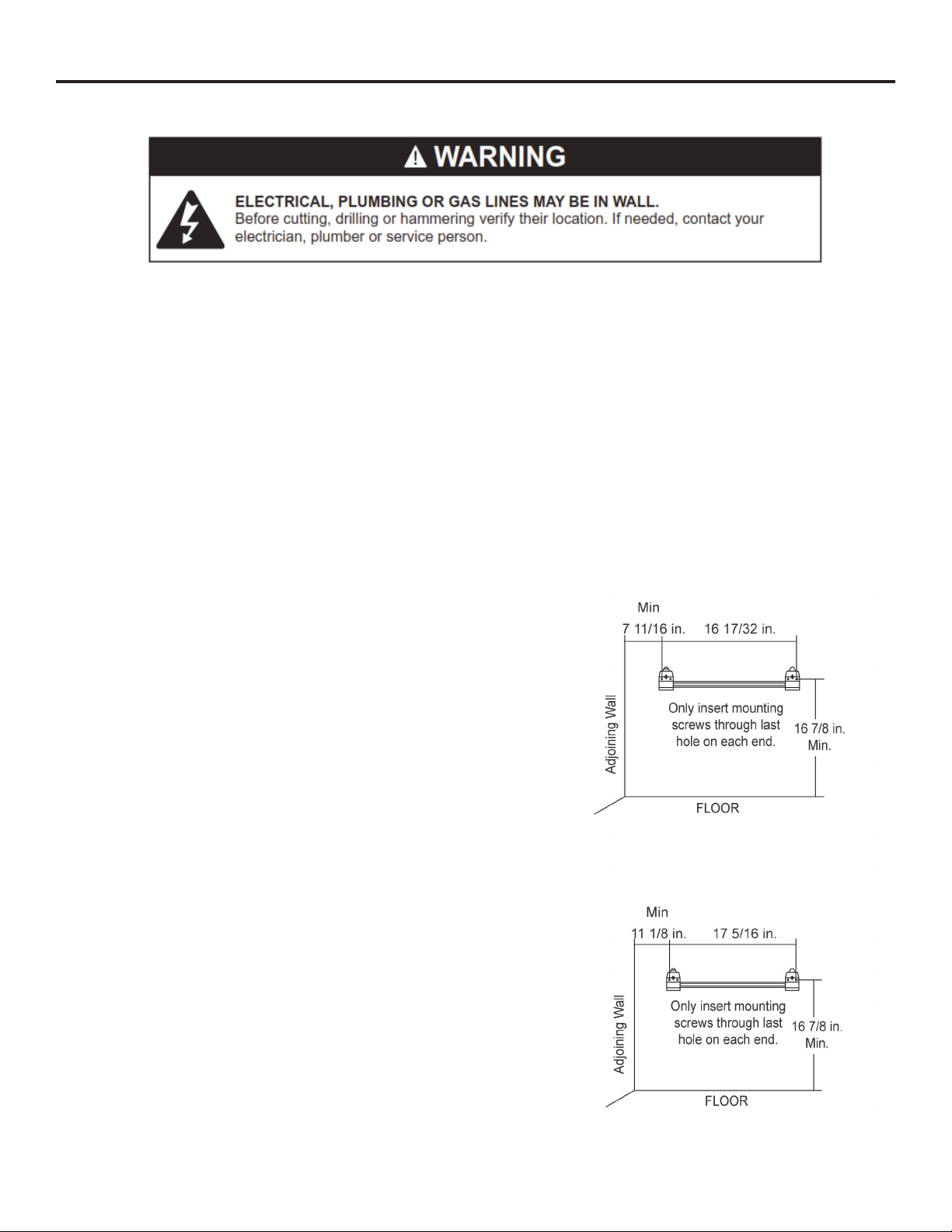
Marking Screw Locations
1. Tape mounting bracket to wall where heater
will be located. Make sure mounting bracket
is level.
2. Mark screw locations on wall (See Fig. 16).
Note: Mark only last hole on each end of
mounting bracket. Insert (2) wood screws
(ST.8*45-16) total through these holes only.
3. Remove tape and mounting bracket
from wall.
Attaching Mounting Bracket To Wall
Note: Expansion bracket, wood screws (ST.8*45-16),
and wall hanging spacers are in hardware package.
The hardware package is provided with heater.
Attaching to Wall Stud Method
For attaching mounting bracket to wall studs:
1. Drill holes at marked locations using
9/64-inch drill bit.
Fig. 16 - Mounting Bracket
Clearances (inches)
Series BF10D
Series BF20D/30D
GBF30D
2. Place mounting bracket onto wall. Line up last hole
on each end of bracket with holes drilled in wall.
3. Insert wood screws (ST.8*45-16) through bracket
and into wall studs.
4. Tighten wood screws (ST.8*45-16) until mounting
bracket is rmly fastened to wall studs.
5. Check that the bracket is secure before mounting
heater!
14
INSTALLATION
Attaching to Expansion Bracket Method
For attaching mounting bracket to hollow walls (wall areas
between studs) or solid walls (concrete or masonry):
1. Drill holes at marked locations using 5/16-inch drill bit.
For solid walls (concrete or masonry), drill at least
1 inch deep.
2. Fold wall expansion bracket as shown in (See Fig. 17).
3. Insert wall expansion bracket (wings rst) into hole. Tap
expansion bracket ush to wall.
4. For thin walls (1/2 inch or less), insert expansion
bracket tool into expansion bracket. Push expansion
bracket tool to “pop” open expansion bracket wings
(See Fig. 18).
IMPORTANT: Do not hammer expansion bracket tool!
For thick walls (over 1/2 inch thick) or solid walls, do not
pop open wings.
5. Place mounting bracket onto wall. Line up last hole on
each end of bracket with expansion bracket.
Fig. 17 - Folding Anchor
Fig. 18 - Popping Open Anchor
Wing For Thin Walls
Fig. 19a - Attaching Wall
Hanging Spacers to Heater
6. Insert expansion bracket screws (ST4.8*15-16) through
wall mounting bracket and into expansion brackets.
7. Tighten expansion bracket screws (ST4.8*15-16) until
mounting bracket is rmly fastened to wall.
8. Check that the bracket is secure before mounting
heater!
Attaching Wall Hanging Spacers to Heater
WARNING: Failure to properly install the wall hanging
spacers may result in property damage, personal injury
or even death.
1. Locate spacer mounting holes on the lower right/left
sections of the heater back panel.
2. Secure (2) wall hanging spacers to heater back panel
using (2) wall hanging spacer screws (M4*25) (See Fig.
19a).
Placing Heater On Mounting Bracket
Spacers
Fig. 19b - Mounting Heater
Onto Mounting Bracket
Horizontal Slots
1. Locate two horizontal slots on back panel of heater.
2. Place heater onto mounting bracket. Slide horizontal
slots onto stand-out tabs on mounting bracket. Be sure
spacers rest evenly against wall (See Fig. 19b).
15

INSTALLATION
CONNECTING TO GAS SUPPLY
WARNING: A qualied service technician must connect heater to gas supply. Follow all local
codes.
IMPORTANT: This appliance requires a 3/8-inch NPT (National Pipe Thread) inlet connection to
the pressure regulator. Never connect the heater to private (non-utility) gas wells, commonly
known as wellhead gas.
WARNING: Do not overtighten gas connections.
CAUTION: Use only new, black iron or steel pipe. Internally tinned copper tubing may be used
in certain areas. Check your local codes. Use pipe of 1/2-in. diameter or greater to allow proper
gas volume to heater. If pipe is too small, undue loss of pressure will occur.
CAUTION: Two gas line installations at the same time are prohibited. The access plate to the
switching means shall not be opened while the heater is in operation.
CAUTION: Check your gas line pressure before connecting heater to gas line. Gas line pressure
must be a minimum 6'' WC for NG & 11" WC for LP with a max pressure of 14'' WC for NG & 14"
WC for LP. If gas line pressure is higher, regulator damage could occur.
CAUTION: Never connect heater directly to an LP supply. This heater requires an external
regulator (not supplied). Install the external regulator between the heater and gas supply.
CAUTION: Avoid damage to regulator. Hold gas regulator with wrench when connecting into gas
piping and/or ttings.
CAUTION: Use pipe joint sealant that is resistant to gas (Propane or Natural Gas).
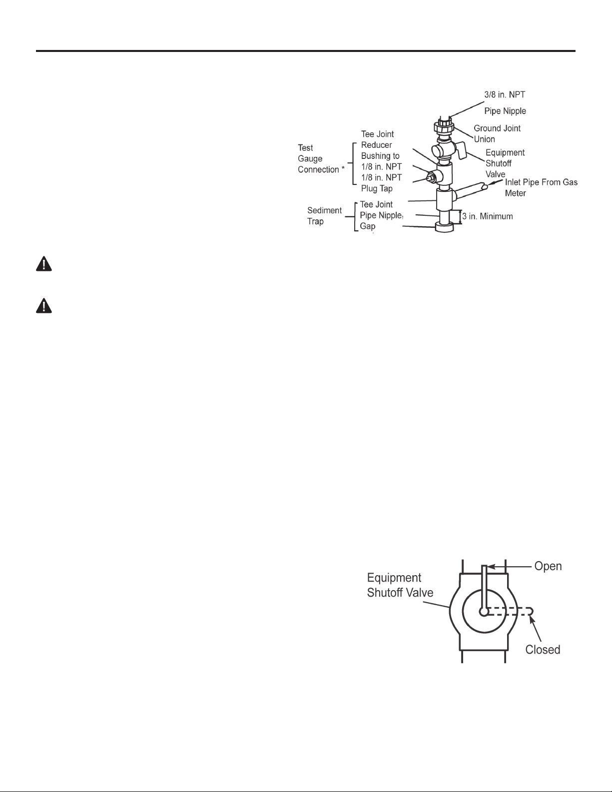
Typical Inlet Pipe Diameters
Use 3/8-inch black iron pipe or greater. Installation must include an equipment shutoff valve, union,
and plugged 1/8-inch NPT tap.
Locate NPT tap within reach for test gauge hook up. NPT tap must be upstream from heater
(see Fig. 20).
IMPORTANT: Install an equipment shutoff valve in an accessible location. The equipment shutoff
valve is for turning on or shutting off the gas to the appliance.
Apply pipe joint sealant lightly to male threads. This will prevent excess sealant from going
into pipe. Excess sealant in pipe could result in clogged heater valves.
16
INSTALLATION
Install sediment trap in supply line as shown
(See Fig. 20). Place sediment trap where it is
within reach for cleaning. Place sediment trap
where trapped matter is not likely to freeze. A
sediment trap traps moisture and contaminants.
This keeps them from going into heater controls.
If sediment trap is not installed or is installed
wrong, heater may not run properly.
CHECKING GAS CONNECTIONS
WARNING: Test all gas piping and connections for leaks after installing or servicing. Correct all
leaks immediately.
WARNING: Never use an open ame to check for a leak. Apply a 50/50 mixture of liquid soap and
water to all joints. If bubbles form, there may be a leak. Correct all leaks immediately.
Pressure Testing Gas Supply Piping System
Test Pressures In Excess Of 1/2 PSIG ( 3.5kPa )
Fig. 20 - Gas Connection
The appliance and its appliance main gas valve must be disconnected from the gas supply piping
system during any pressure testing of that system at test pressures in excess of ½ psi (3.5 kPa).
Pressure Testing Gas Supply Equal To or less than
1/2 PSIG ( 3.5kPa )
The appliance must be isolated from the gas supply piping system by closing its equipment shut-off
valve during any pressure testing of the gas supply piping system at test pressures equal to or less
than ½ psi (3.5 kPa).
Leak Testing Heater Gas Internal Connections
1. Open equipment shutoff valve (See Fig. 21).
2. Make sure control knob of heater is in the OFF position.
3. Open gas supply tank valve (LP systems).
4. Check all joints from equipment shutoff valve to control
valve. Apply 50/50 mixture of liquid soap and water
to gas joints. If bubbles form, there may be a leak.
5. Light heater (see Operation, page 18). Check all other
internal joints for leaks.
6. Turn off heater (see "To Turn Off Gas to Appliance,"
page 19).
17
Fig. 21 - Equipment Shut -off Valve
 Loading...