

Page 1
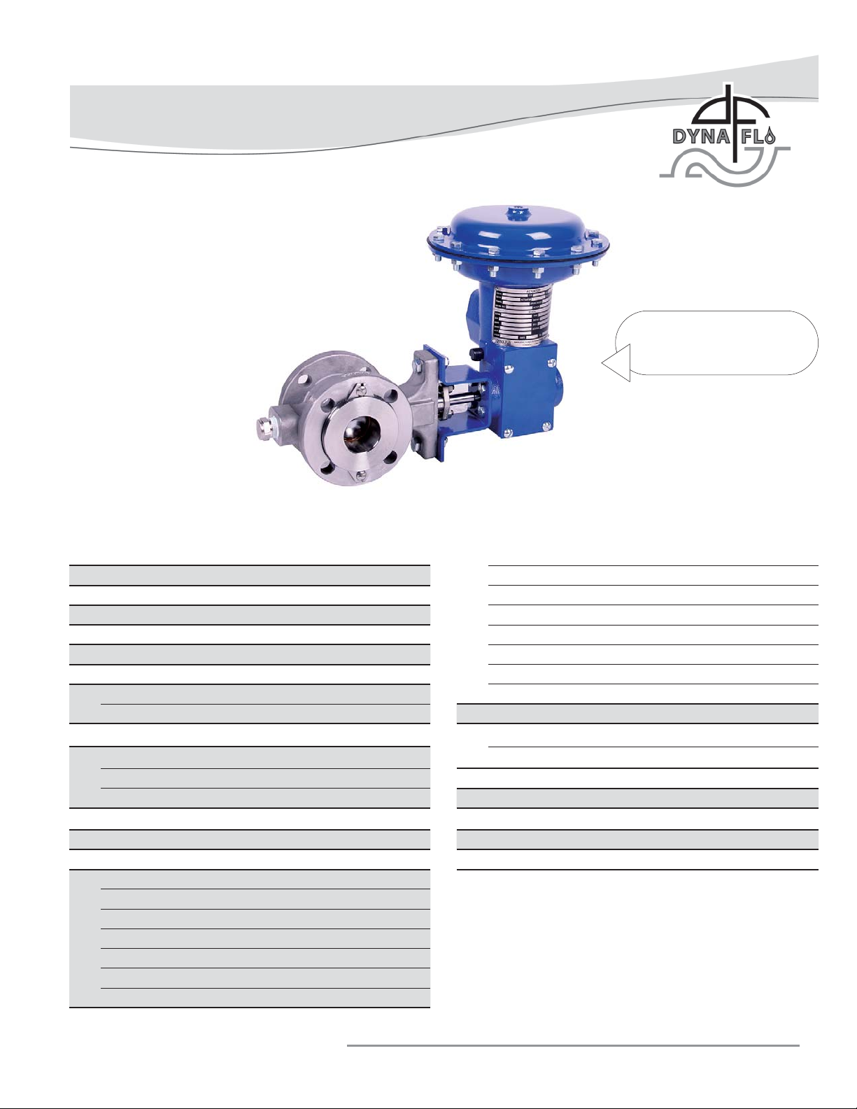
Model DFR 026 Rotary Actuator
Operation, Parts, and Instruction Manual
Figure 1 DFR 026
and 571 Control Valve
TABLE OF CONTENTS
General 2 Actuator Assembly 14
Scope 2 Bushing Installation 14
Principles of Operation 2 Mounting Yoke / Hub Assembly 14
Safety Caution 2 Spring / Adjuster / Seat Assembly 15
Specifi cations 3 Diaphragm Rod / Plate Assembly 15
Approximate Actuator Weights - Table 1 3 Lever Assembly & Installation 16
Unpacking 4 Diaphragm Casing Assembly 17
Installation 4 Access Plate Installation 17
Air Piping 4 Principles of Handwheel Operation 18
Actuator Mounting 5 Handwheel Maintenance 18
Spring Adjustment 7 O-Ring Replacement 18
Initial Set 7 Actuator Cross Section - Figure 26 20
Stroke Range 8 Mounting Bolt Torques - Table 3 21
Changing Actuator Style 8 DFR Torque Specifi cations - Table 4 21
Mounting Styles & Positions - Table 2 9 Parts 22
Mounting Orientations - Figure 10 10 Model Builder 24
Actuator Disassembly 11
Valve Removal 11
Casing Disassembly 11
Diaphragm Plate / Rod Remov al / Disassembly 12
Spring / Adjuster / Seat Disassembly 13
Mounting Yoke / Hub Removal 13
Bushing Inspection / Removal 14
Dyna-Flo Control Valve Services Ltd.
Phone: 780 • 469 • 4000 Toll Free: 1 • 866 • 396 • 2356 Fax: 780 • 469 • 4035 Website: www.dynafl o.com
P-DFR1M0918A
1
Page 2

Model DFR 026 Rotary Actuator
Operation, Parts, and Instruction Manual
NOTICE These instructions are meant to be used with the Dyna-Flo DFR Technical Sales Bulletin as they refer to
Figures and Tables therein. If you do not have the Technical Sales Bulletin, contact Dyna-Flo immediately,
or visit www.dynafl o.com.
Each control valve is factory checked. Check the calibration for the specifi c application, before a valve
or actuator is put into service.
It is the intention of this document to provide users with an accurate guide for safe installation and
maintenance of the DFR Actuator. Revisions and updates are available at above mentioned website.
GENERAL
The following instructions are to be thoroughly reviewed and understood prior to installing, operating or performing
maintenance on this equipment. Work on this equipment should be performed by experienced personnel. Throughout
the manual, safety and caution notes appear and must be strictly followed to prevent serious injury or equipment
malfunction.
SCOPE
The actuator confi guration and construction materials were selected to meet particular pressure, temperature, operating medium,
and process fl uid conditions. Some material combinations are limited in their pressure and temperature ranges. Do not apply any
other conditions to the actuator without fi rst contacting your Dyna-Flo sales offi ce.
This manual is written to be a practical and useful guide for maintaining the Dyna-Flo DFR Actuator.
PRINCIPLES OF OPERATION (For Top-Mounted Handwheel refer to Page 18)
The DFR actuator works by loading pressure on the top side of the diaphragm (Key 23), this loading pressure moves the diaphragm
rod (Key 16) downwards. As the loading pressure is decreased, the spring (Key 14) forces the diaphragm rod upwards.
The spring and diaphragm have been selected to meet a specifi c application requirement, and while in service the actuator should
produce full travel of the valve with the diaphragm pressure indicated on the nameplate (Key 33).
If there is no positioner being used with the control valve, a loading device (such as a 4-way switching valv e) must be used. L oading
devices do not come equipped standard with the actuator. Refer to appropriate positioner instruction manual as required.
SAFETY CAUTION
Only well trained experienced technicians should perform these procedures. Use safe work practices and lock out
procedures when isolating valves and actuators. It is also important to wear the proper protective equipment when
performing any installation or maintenance activity. Use only parts and materials rated for the process being used,
operating conditions, and environmental conditions products will be used in.
To avoid personal injury or installation damage as a result of the sudden release of process pressure or damage to
equipment, do not install the actuator assembly where service conditions could exceed the limits stated in this manual,
sales bulletin or on the equipment nameplates. Use government codes, accepted industry standards and good piping
practices, and select proper pressure-relieving equipment for protection of your installation. Always be aware of
fl ammable process and instrument gas.
Always be aware of the hazards of actuators, especially spring-loaded actuators. Be sure that the actuator is
de-energized or in the failed position before performing any maintenance procedure.
These actuators have dangerous pinch points. Never put your hands inside the valve or actuator unless you are certain
that the valve or actuator will not suddenly move.
Dyna-Flo Control Valve Services Ltd.
Phone: 780 • 469 • 4000 Toll Free: 1 • 866 • 396 • 2356 Fax: 780 • 469 • 4035 Website: www.dynafl o.com
P-DFR1M0918A
2
Page 3
Model DFR 026 Rotary Actuator
Operation, Parts, and Instruction Manual
SPECIFICATIONS
Actuator Size
026 27 (174) 60 (414)
Material Temperature Capabilities
Standard: -40 to 180
Construction Materials
See Parts list for construction materials.
Contact your Dyna-Flo sales offi ce for more information and
other options.
Valve Shaft Compatibility, inches (mm)
Size 026: 1/2 (12.7) & 5/8”x1/2”
Actuator Dimensions
Refer to Figures 3 & 4 of Sales Bulletin.
Refer to Tables 2, 3, & 4 of Sales Bulletin.
Output Torque
Refer to Tables 5 & 6 of Sales Bulletin.
Active Diaphragm
Area in2 (cm2)
o
F (-40 to 82 oC).
Maximum Casing
Pressure Psig (kPa)
Standard Tubing Connection Size
1/4 inch NPT.
Maximum Shaft Rotation
90 degrees.
Shaft Connection Types
The standard shaft connection is a splined shaft suitable for a
Dyna-Flo 570 control valve.
Options
• Manual override
• Reduced rotation output
• Increased tubing connection size
• Travel stops
Diaphragm Casing Volume
Refer to Table 7 of Sales Bulletin.
For more information and other options contact your Dyna-Flo
Actuator Mounting Orientation And Valve Applications
Refer to Figure 10.
Refer to Table 2.
Approximate Actuator Weights - lb. (Kg)
Actuator Size
026 30 (14) 41 (19)
Standard Assembly With Top Mounted Handwheel
Dyna-Flo Control Valve Services Ltd.
Phone: 780 • 469 • 4000 Toll Free: 1 • 866 • 396 • 2356 Fax: 780 • 469 • 4035 Website: www.dynafl o.com
sales offi ce.
P-DFR1M0918A
Table 1
3
Page 4
Model DFR 026 Rotary Actuator
Operation, Parts, and Instruction Manual
UNPACKING VALVE FROM SHIPPING
CONTAINER
Special Tools Required:
• Properly Rated Lifting Straps (2 – 4 Straps) See Table 1 for
actuator weights.
• Lifting Device (Example: Crane)
Check the packing list, verify that the list includes all the
materials in the shipping container before unpacking. Valve
information can be found on the nameplate (Key 33). Refer to
Figure 3 for nameplate location.
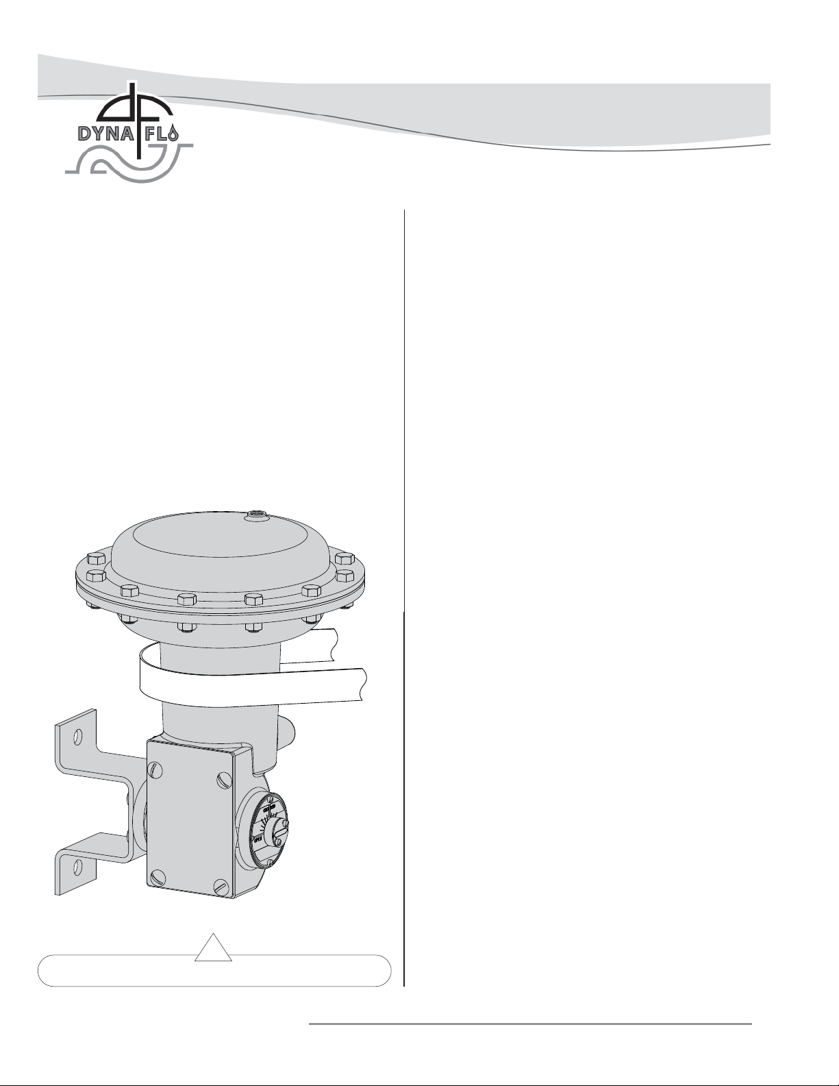
When lifting the valve from shipping container, place properly
rated lifting straps around the neck of the actuator (See Figure
2) to lift the valve/actuator assembly. Straps should be placed
to avoid damage to tubing and other mounted accessories.
INSTALLATION
Before You Begin:
• Read the General and Scope section of this manual (Page 2).
• Read Safety Caution (Page 2).
• Sudden movement of actuator can cause damage or injury.
It helps to have the actuator de-energized as long as the
valve installation will permit.
• Use safe work practices and lock out procedures before
placing valve in-line.
Actuators are typically shipped from factory as an assembly
already mounted to the valve. Follow the appropriate valve
installation instructions to install the actuator / valve assembly.
If the actuator was shipped separately, it will be necessary to
mount the actuator on the valve prior to installation, refer to
the Actuator Mounting section.
Operating medium must be controlled and directed, if a
positioner was not ordered or unavailable, use a loading
device such as a 4-way switching valve (not provided with the
actuator). For more information on positioner installation and
operation, refer to the appropriate positioner instruction
manual for your positioner type.
LIFTING STRAP
AIR PIPING
WARNING:
Property damage, environmental harm, and personal injury
can result from the use of supply gas other than clean,
non-corrosive, oil and moisture free air. Do not exceed the
supply pressure indicated on the nameplate (Key 33)
located on the actuator.
Before You Begin:
Note: Standard actuators accept 1/4” (6 mm) NPT connections.
Piping Installation Steps:
1 Use 3/8” (10 mm) outside diameter SST tubing
(or equivalent) for air lines. Keep length of tubing as short
as possible to prevent transmission lag in the control
signal.
2 Install the required line vents, valves, drains, seals, and
fi lters to the actuator.
Figure 2 Actuator Lifting Suggestions
Dyna-Flo Control Valve Services Ltd.
Phone: 780 • 469 • 4000 Toll Free: 1 • 866 • 396 • 2356 Fax: 780 • 469 • 4035 Website: www.dynafl o.com
P-DFR1M0918A
4
Page 5
Model DFR 026 Rotary Actuator
Operation, Parts, and Instruction Manual
ACTUATOR MOUNTING
Before You Begin:
• Read the General and Scope section of this manual (Page 2).
• Read Safety Caution (Page 2).
• Use safe work practices and lock out procedures.
• Disconnect supply lines (air or gas), electric power, or control
signal to the actuator. Sudden movement of actuator can
cause damage or injury, make sure actuator will not operate.
• Vent any pneumatic actuator loading pressure.
• Relieve process pressure and drain the process fl uid from up
and down stream of valve.
• Be aware of potentially hazardous process material that may
be present in-line and in-valve. Isolate the valve from
process pressure. Use a bypass or block valve if necessary,
or completely shut off the process. Relieve internal valve
pressure (refer to the appropriate valve instruction manual).
Lubricants Required:
• Fluid Film® (Key D)
3
28
27
33
TURN THE HUB
(KEY 5) TO
ALIGN THE
TRAVEL
INDICATOR
(KEY 6) WITH
THE DESIRED
ORIENTATION
ON THE
TRAVEL SCALE
(KEY 8).
6
8
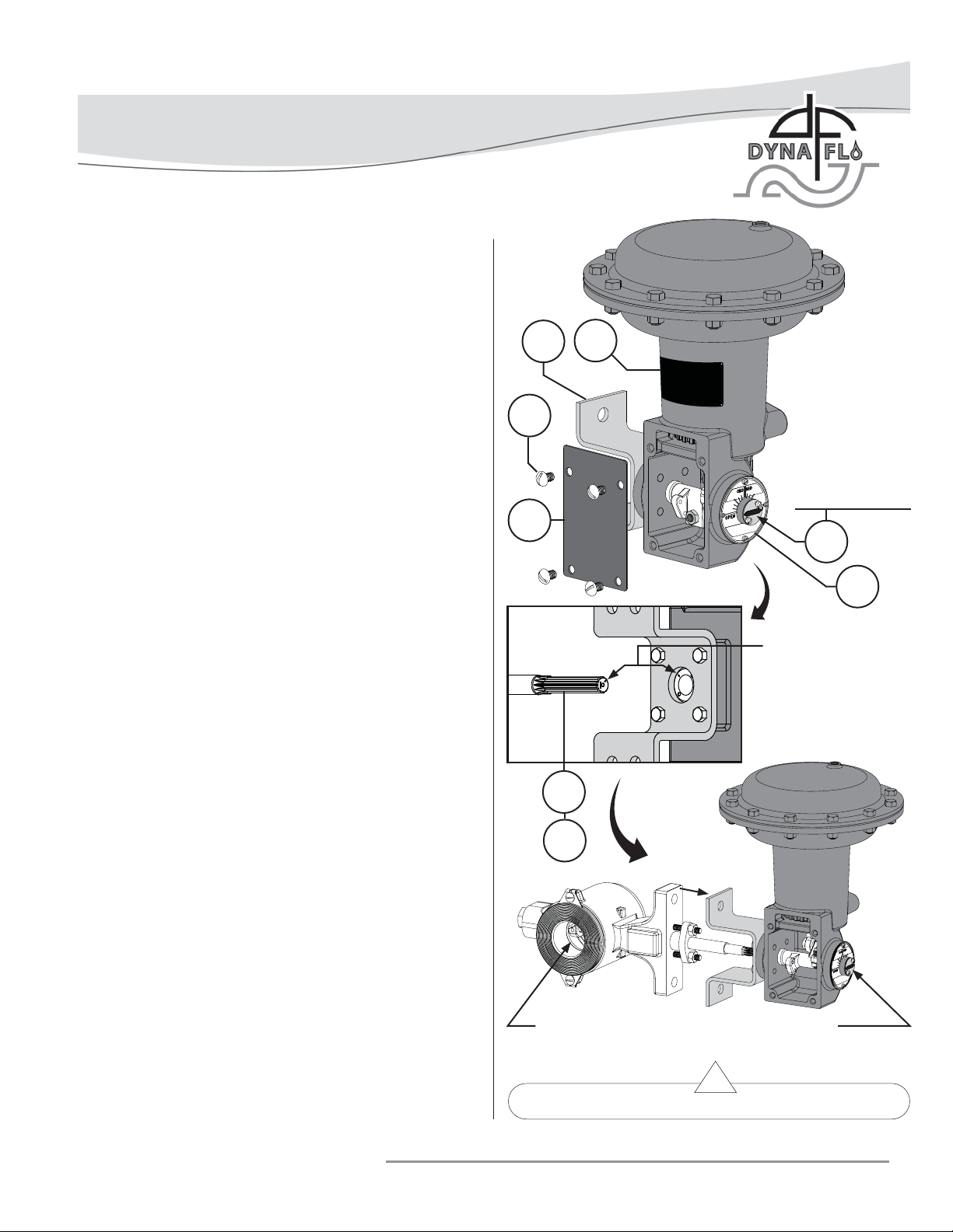
1 If the valve has been removed from the pipeline, secure
the valve assembly in place on a fl at work surface
that will support the weight of the combined valve and
actuator assembly.
2 Remove any positioners and/or instrumentation installed
on the actuator.
3 Remove the access plate (Key 27) by removing the screws
(Key 28).
4 Before placing the valve shaft (Key V) into the lever (Key
19), position the valve ball/disc as follows:
For push-down-to-close action (fail open):
Rotate the valve ball/disc into the fully open position.
For push-down-to-open action (fail closed):
Rotate the valve ball/disc into the fully closed position.
Note: Refer to the appropriate valve instruction manual.
5 Loosen the lever clamp (Keys 19A & 19B). Refer to Figure 26.
6 Apply Fluid Film® (Key E) to the teeth of the valve shaft
(Key V).
7 Position the hub (Key 5) and travel indicator (Key 6) in
the desired position. Note: It may be necessary to pull the
valve shaft (Key V) back out of the hub after installation
should the hub and travel indicator sit in an undesired
position once the shaft is installed.
ALIGN THE MARK
ON THE VALVE
SHAFT (KEY V)
WITH THE MARK
ON THE LEVER
(KEY 19).
V
D
THE POSITION OF THE VALVE BALL/DISC
SHOULD MATCH THE POSITION OF THE TRAVEL
INDICATOR (KEY 6).
Figure 3 Actuator Mounting
Dyna-Flo Control Valve Services Ltd.
Phone: 780 • 469 • 4000 Toll Free: 1 • 866 • 396 • 2356 Fax: 780 • 469 • 4035 Website: www.dynafl o.com
P-DFR1M0918A
5
Page 6
30
Model DFR 026 Rotary Actuator
Operation, Parts, and Instruction Manual
OPERATING PRESSURE
SUPPLY LINE WITH MAXIMUM
OPERATING
PRESSURE
APPLIED
TO ACTUATOR.
UP STOP
(KEYS 20
& 21)
6
VALVE BALL
NOT 100%
CLOSED.
3231
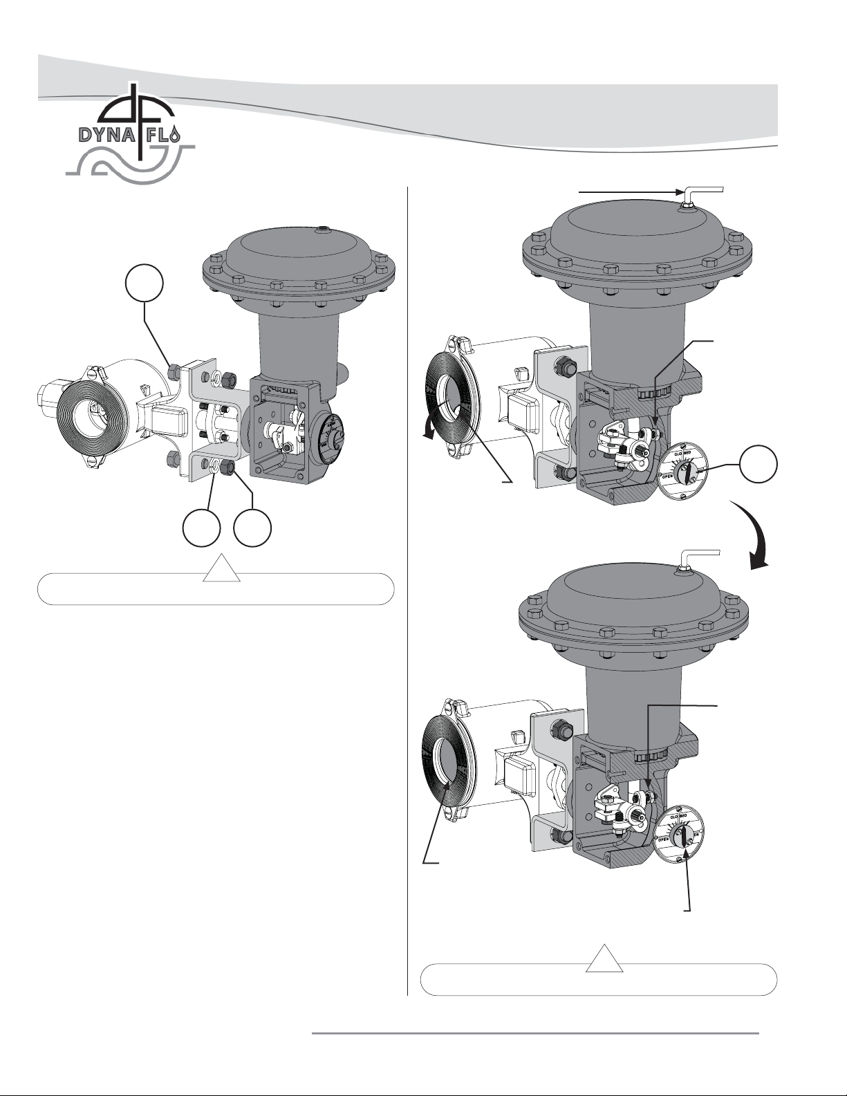
Figure 4 Actuator/Valve Body Bolting
ACTUATOR MOUNTING (Continued)
8 Slide the actuator onto the valve shaft as shown in Figure
3. Refer to Figures 10 for actuator mounting positions and
orientations.
Note: The actuator is typically installed in a vertical
orientation. Should the actuator be installed in a horizontal
position, then it may be necessary to have external support
for the actuator in this position.
9 Once the actuator is installed on the valve shaft in the
proper orientation, secure the actuator in place using the
mounting bolts (Key 30), lockwashers (Key 31), and hex
nuts (Key 32). Refer to Figure 4, and Table 3 for torque
values.
10 Center the lever (Key 19) and secure it by tightening the
lever clamp cap screw (Key 19A) and jam nut (Key 19B).
11 Loosen the jam nut (Key 21) on the up travel stop. Adjust
the up travel stop (Key 20) so that the valve ball/disc is
in the fully open or closed position as required. Lock the
travel stop in place by re-tightening the jam nut. Refer to
Figure 6.
UP STOP
ADJUSTED
TO CLOSE
VALVE
VALVE BALL
100% CLOSED
TRAVEL INDICATOR (KEY 6)
SHOWS VALVE IS PROPERLY
CLOSED
Figure 5 Mounting Adjustment for Push-Down-To-Open
Dyna-Flo Control Valve Services Ltd.
Phone: 780 • 469 • 4000 Toll Free: 1 • 866 • 396 • 2356 Fax: 780 • 469 • 4035 Website: www.dynafl o.com
P-DFR1M0918A
6
Page 7
Model DFR 026 Rotary Actuator
Operation, Parts, and Instruction Manual
ACTUATOR MOUNTING (Continued)
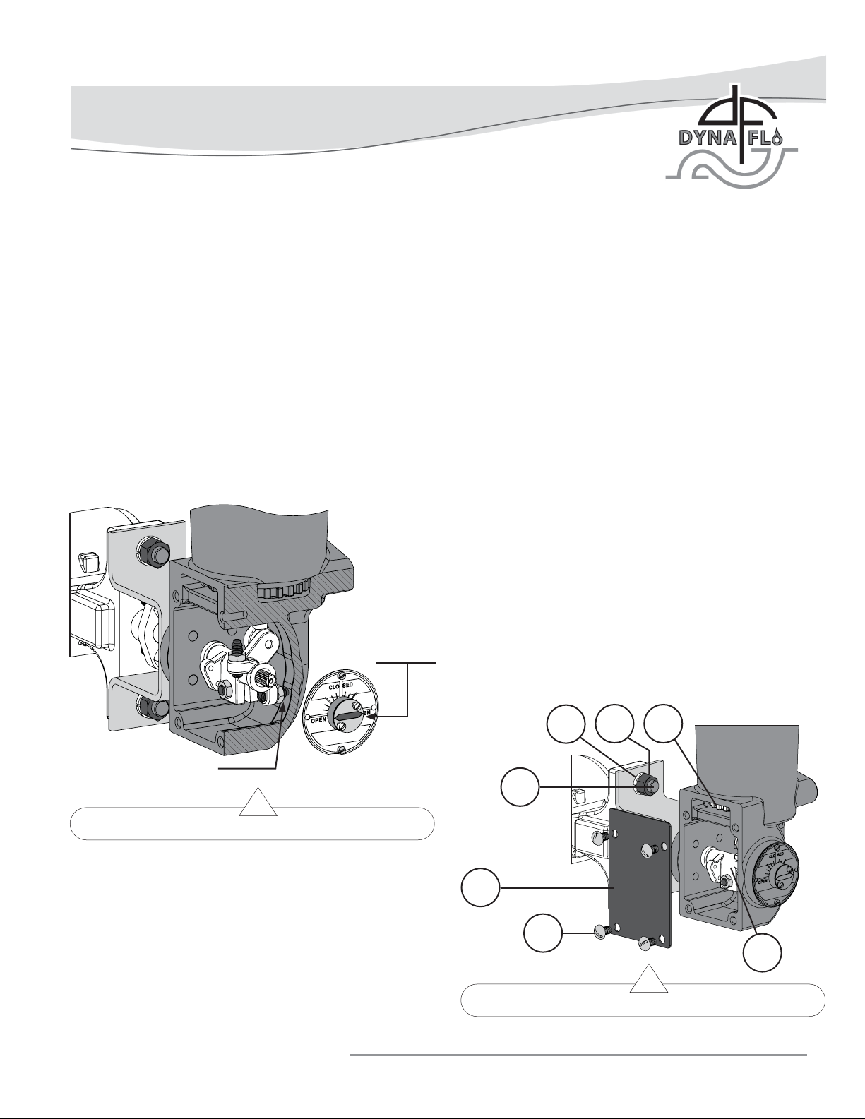
12 Slowly stroke the actuator until the maximum operating
pressure is reached as indicated on the nameplate (Key
33). Note: Use caution when stroking the actuator, avoid
dangerous pinch points and equipment damage by keeping
appendages and tools away from moving actuator parts.
13 With the maximum operating pressure applied to the
actuator, loosen the jam nut (Key 21) and adjust
the down travel stop (Key 20, Figure 5) until the valve
ball/disc is in the fully closed or open position as required.
Lock the travel stop in place by re-tightening the jam nut.
14 Relieve the operating pressure from the actuator casing.
15 Perform the SPRING ADJUSTMENT - Initial Set.
TRAVEL
INDICATOR
(KEY 6)
SHOULD POINT
TO OPEN
• Vent any pneumatic actuator loading pressure.
• Relieve process pressure and drain the process fl uid from up
and down stream of valve.
• Be aware of potentially hazardous process material that may
be present in-line and in-valve. Isolate the valve from
process pressure. Use a bypass or block valve if necessary,
or completely shut off the process. Relieve internal valve
pressure (refer to the appropriate valve instruction manual).
Special Tools Required:
• Flat-head screwdriver or fl at-bladed tool.
INITIAL SET
Refer to the actuator nameplate (Key 33) for the Initial Set.
The initial setting is the casing pressure at which the diaphragm
(Key 23) begins to move the diaphragm plate (Key 17) and
diaphragm rod (Key 16) away from the up travel stop.
The initial setting was selected to meet a specifi c set of service
condition requirements. Proper initial setting will ensure that
once the actuator and valve are in service, the valve will seat
properly and full travel will be achieved within the specifi ed
diaphragm casing pressure range.
Note: If the actuator has been disassembled and reassembled,
or if service requirements have changed, it will be necessary
to perform the following steps for Initial Setting. Refer to the
Actuator Mounting section (Page 5) before proceeding with the
spring adjustment.
31
32
12
ADJUST DOWN STOP
(KEY 20 & 21)
30
Figure 6 Mounting Adjustment for Push-Down-To-Close
SPRING ADJUSTMENT
Before You Begin:
• Read the General and Scope section of this manual (Page 2).
• Read Safety Caution (Page 2).
• Use safe work practices and lock out procedures.
• Disconnect supply lines (air or gas), electric power, or control
signal to the actuator. Sudden movement of actuator can
cause damage or injury, make sure actuator will not operate.
Dyna-Flo Control Valve Services Ltd.
Phone: 780 • 469 • 4000 Toll Free: 1 • 866 • 396 • 2356 Fax: 780 • 469 • 4035 Website: www.dynafl o.com
27
28
Figure 7 Access Plate Removal
P-DFR1M0918A
19
7
Page 8
Model DFR 026 Rotary Actuator
Operation, Parts, and Instruction Manual
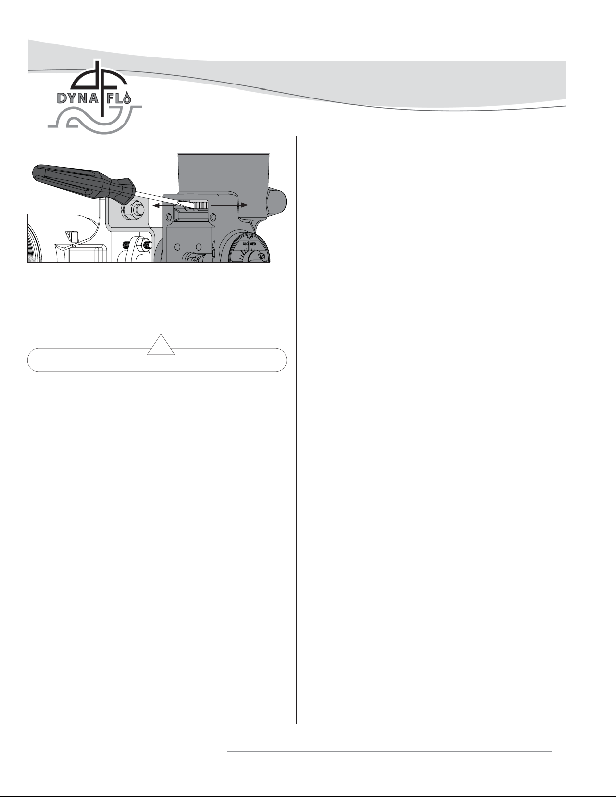
TURNING THE SPRING
ADJUSTER (KEY 12)
CLOCKWISE (TO THE
LEFT) WILL INCREASE
THE INITIAL SETTING.
Figure 8 Spring Adjustment
SPRING ADJUSTMENT (Continued)
INITIAL SET (Continued)
1 When performing spring adjustment on the DFR 026, it will
be necessary to have a valve shaft (Key V) inserted into
the actuator and to approximately pre-adjust the up travel
stop to its desired position. Note: Travel error will occur if
this step is not followed.
2 Disconnect any instrumentation attached to the actuator.
3 Remove the screws (Key 28) and the access plate (Key 27).
4 Apply operating pressure to the diaphragm casing, when
the spring is properly adjusted, the diaphragm rod (Key
16) will start to move when the Initial Set pressure
(indicated on the nameplate (Key 33) or in Table 5) is
reached. Make note whether the diaphragm rod started to
move before or after the Initial Set value.
5 Relieve actuator casing pressure.
6 Using a fl at-head screwdriver or a fl at-bladed tool,
adjust the spring adjuster (Key 12) accordingly:
• To increase Initial Setting (increase spring compression)
– Turn the spring adjuster to the left (clockwise when
viewed from above).
• To decrease Initial Setting (decrease spring compression)
– Turn the spring adjuster to the right (counter clockwise when viewed from above).
TURNING THE SPRING
ADJUSTER (KEY 12)
COUNTER-CLOCKWISE
(TO THE RIGHT) WILL
DECREASE THE INITIAL
SETTING.
7 Repeat Steps 4 – 6 until the Initial Set pressure is reached.
8 Re-install the access plate (Key 27) and screws (Key 28).
9 Check the position of the travel indicator (Key 6), adjust if
necessary.
STROKE RANGE
Should the desired stroking range be unachievable during
normal operating conditions with the casing pressure used,
it may be possible to adjust the stroking range by making a
spring adjustment. A spring adjustment will shift the casing
pressure span and either increase or decrease the casing
pressure at which the actuator begins its stroke, this will
affect the pressure at which the actuator reaches full travel.
Refer to the Initial Set section and adjust the spring adjuster
(Key 12) as follows:
To shift the casing pressure span downward – rotate the
spring adjuster to the right (counter-clockwise when viewed
from above).
To shift the casing pressure span upward – rotate the
spring adjuster to the left (clockwise when viewed from above).
CHANGING ACTUATOR STYLE
Refer to the Before You Begin section of the Actuator Mounting
instructions (Page 5).
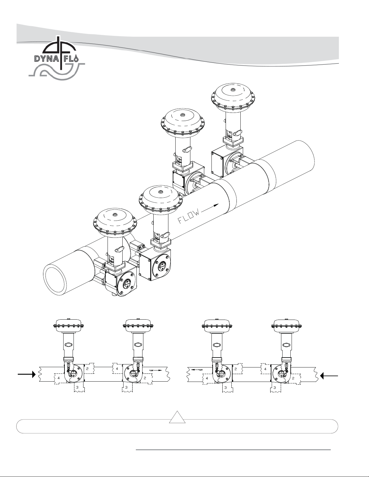
Mounting Styles A and D
Style A is right-hand mounted and Style D is left-hand
mounted, in all other ways Styles A and D are identical.
Refer to Figure 10.
Mounting Styles B and C
Style B is right-hand mounted and Style C is left-hand
mounted, in all other ways Styles B and C are identical.
Refer to Figure 10.
Note: To convert a Style A or D into a Style B or C actuator,
the actuator must fi rst be separated from the control valve.
Refer to Steps 1-4 of the Disassembly Section and 1-2 of Valve
Removal Section (Page 11).
Refer to Figure 9.
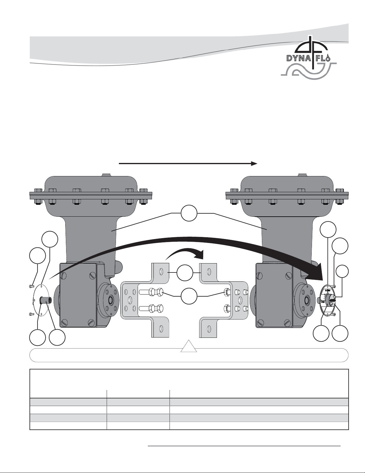
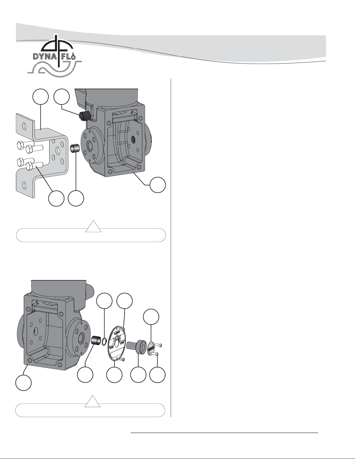
1 Remove the machine screws (Key 10) and travel scale/hub
assembly (Keys 5, 6, 7, 8, & 9).
2 Remove the cap screws (Key 4) and mounting yoke (Key
3).
Dyna-Flo Control Valve Services Ltd.
Phone: 780 • 469 • 4000 Toll Free: 1 • 866 • 396 • 2356 Fax: 780 • 469 • 4035 Website: www.dynafl o.com
P-DFR1M0918A
8
Page 9
Model DFR 026 Rotary Actuator
Operation, Parts, and Instruction Manual
CHANGING ACTUATOR STYLE (Continued)
3 Swap the position of the travel scale/hub assembly (Keys 5, 6, 7, 8, & 9) and mounting yoke (Key 3) as shown in
Figure 9. Install the travel scale/hub assembly on the opposite side of the actuator using the machine screws (Key 10).
4 Place the mounting yoke (Key 3) in the desired orientation (refer to Table 2 and Figure 10 for Mounting Positions) on the
opposite side of the actuator. Secure the mounting yoke in place using the cap screws (Key 4), tighten the cap screws to the
torque specifi cation listed in Table 4.
5 Once an actuator has been converted to a different mounting style, the actuator must be re-adjusted. Refer to the Spring
Adjustment section of this manual.
TO
STYLE B / CSTYLE A / D
8
10
9
Model DFR Mounting Styles and Positions
5
Figure 9 Changing Actuator Style
1
8
10
3
7
4
65
Table 2
Mounting Action Model 570 Series Valves Model 660 Butterfl y Valve
Right Hand Fail Open Style A Style B
Right Hand Fail Close Style B Style A
Left Hand Fail Open Style C Style C
Left Hand Fail Close Style D Style D
Dyna-Flo Control Valve Services Ltd.
Phone: 780 • 469 • 4000 Toll Free: 1 • 866 • 396 • 2356 Fax: 780 • 469 • 4035 Website: www.dynafl o.com
P-DFR1M0918A
9
Page 10
Left Hand Mount
Model DFR 026 Rotary Actuator
Operation, Parts, and Instruction Manual
D
C
B
Flow
STYLE A
A
POSITION 1
STYLE B
Right Hand Mount
STYLE D
POSITION 1 POSITION 1
STYLE C
POSITION 1
Flow
RIGHT-HAND MOUNTING LEFT-HAND MOUNTING
Figure 10 Mounting Orientation and Valve Applications
Dyna-Flo Control Valve Services Ltd.
Phone: 780 • 469 • 4000 Toll Free: 1 • 866 • 396 • 2356 Fax: 780 • 469 • 4035 Website: www.dynafl o.com
P-DFR1M0918A
10
Page 11
Model DFR 026 Rotary Actuator
Operation, Parts, and Instruction Manual
ACTUATOR DISASSEMBLY
Before You Begin:
• Read the General and Scope section of this manual (Page 2).
• Read Safety Caution (Page 2).
• Use safe work practices and lock out procedures.
• Disconnect supply lines (air or gas), electric power, or control
signal to the actuator. Sudden movement of actuator can
cause damage or injury, make sure actuator will not operate.
• Vent any pneumatic actuator loading pressure.
• Relieve process pressure and drain the process fl uid from up
and down stream of valve.
• Be aware of potentially hazardous process material that may
be present in-line and in-valve. Isolate the valve from
process pressure. Use a bypass or block valve if necessary,
or completely shut off the process. Relieve internal valve
pressure (refer to the appropriate valve instruction manual).
30
3
V
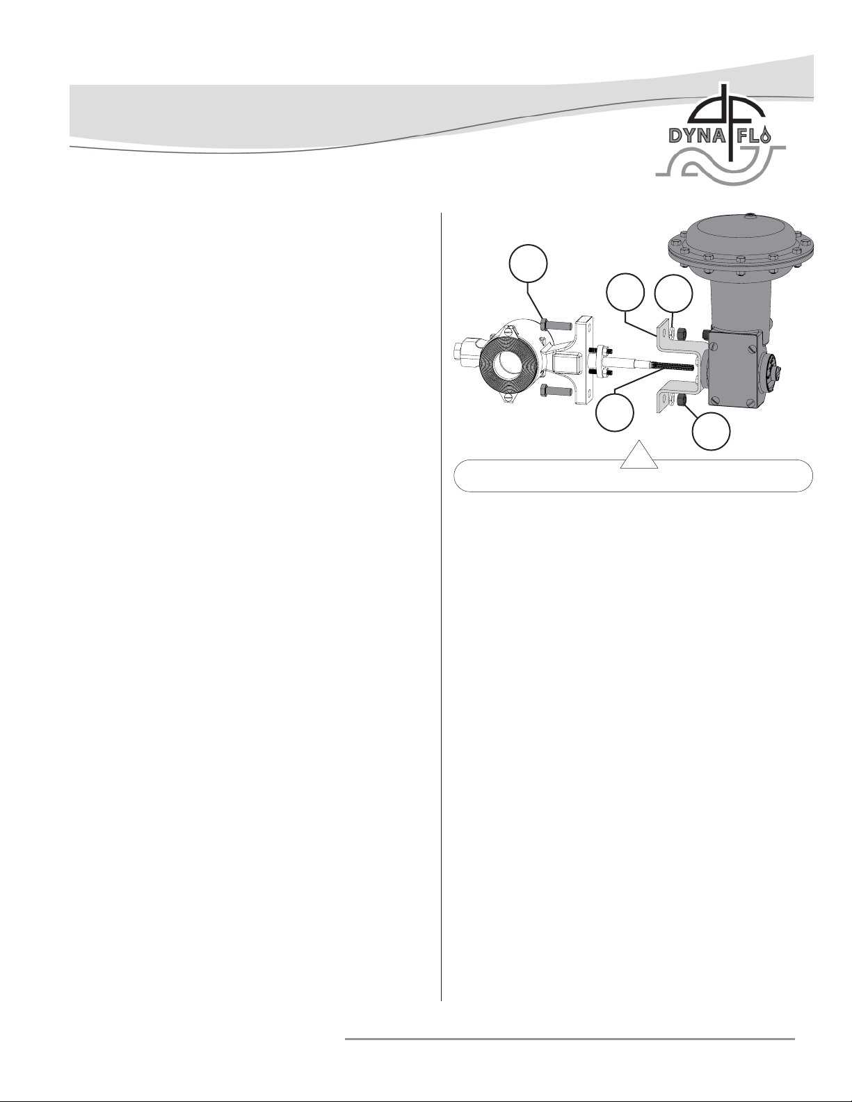
Figure 11 Valve Removal
31
32
Special Tools Required:
• Soft tip felt marker.
• Flat-head screwdriver or fl at-bladed tool.
• Split-ring pliers.
1 If the actuator has been removed from the valve or the
actuator/valve assembly has been removed from the
pipeline, secure either assembly in place on a fl at work
surface that will support the weight.
2 Remove any instruments installed on the actuator.
3 Observe the position of the travel indicator (Key 6). Using
a soft tip felt marker, mark the position of the travel
indicator on the travel scale (Key 8).
4 Relieve all operating pressure and/or rotate the handwheel
counterclockwise to remove spring tension if a handwheel
is installed. For Handwheel Maintenance refer to Page 18.
VALVE REMOVAL
For complete actuator disassembly, it will be necessary to
separate the actuator from the control valve in order to remove
the lever (Key 19). If maintenance is being performed on the
diaphragm (Key 23) or handwheel, separating the actuator
from the valve will not be necessary.
1 Remove the mounting hex nuts (Key 32), lockwashers (Key
31), and mounting bolts (Key 30).
2 Separate the actuator from the valve and slide the actuator
off of the valve shaft (Key V).
CASING DISASSEMBLY
1 For maintenance purposes: To replace the diaphragm
(Key 23), it will not be necessary to remove spring tension
when removing the upper casing (Key 24), the up travel
stop will hold the spring in place. Proceed to Step 4.
For complete actuator disassembly: Proceed as follows.
2 Remove the screws (Key 28) and the access plate (Key
27). Refer to Figure 7.
3 Using a fl at-head screw driver or fl at-bladed tool, remove
all spring tension by turning the spring adjuster (Key 12)
counter-clockwise (to the right) as shown in Figure 8.
4 Remove the casing cap screws (Key 25) and hex nuts
(Key 26).
5 Remove the upper casing (Key 24) and diaphragm (Key
23).
6 Inspect all parts for damage or wear, replace or repair
parts as necessary. All soft parts such as diaphragm should
be replaced.
Dyna-Flo Control Valve Services Ltd.
Phone: 780 • 469 • 4000 Toll Free: 1 • 866 • 396 • 2356 Fax: 780 • 469 • 4035 Website: www.dynafl o.com
P-DFR1M0918A
11
Page 12
Model DFR 026 Rotary Actuator
Operation, Parts, and Instruction Manual
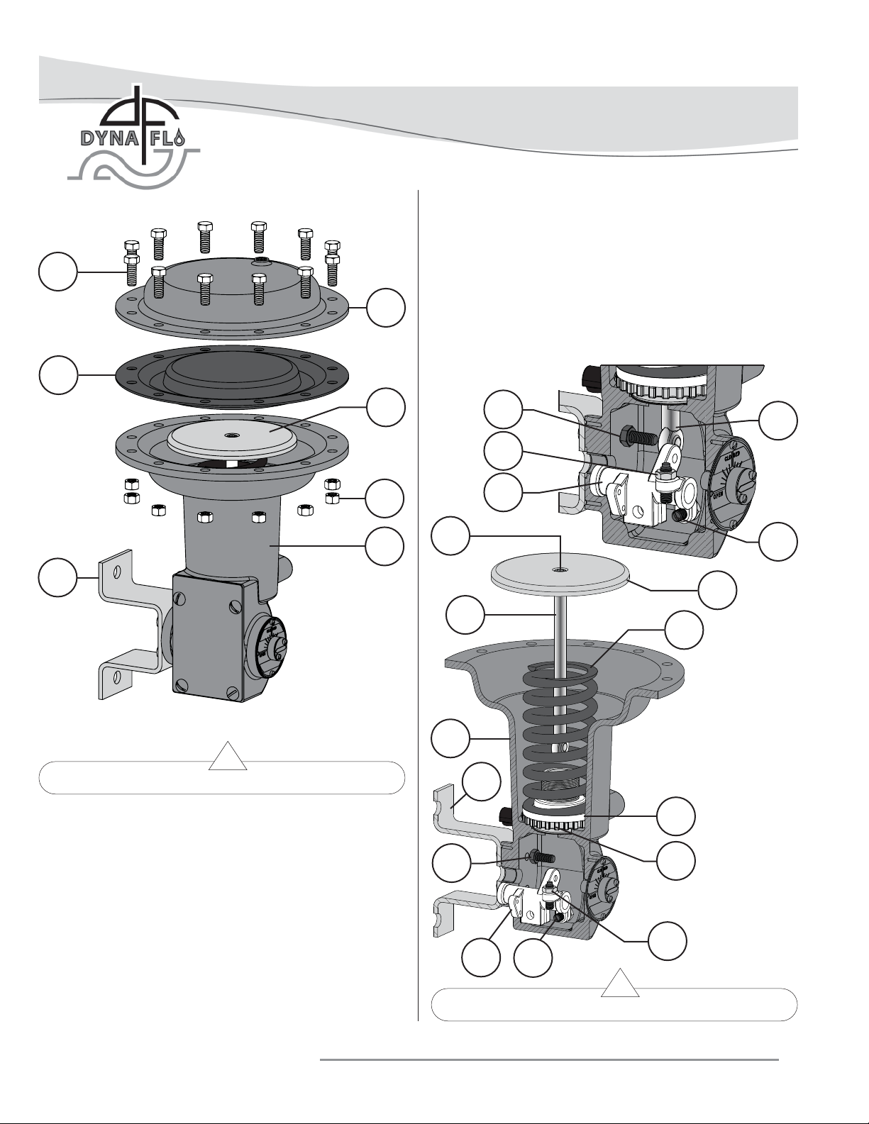
5 Using a 5/16” socket bit, remove the socket head cap
screw (Key 18) from the diaphragm rod (Key 16) and
separate the diaphragm plate (Key 17) from the
diaphragm rod.
25
23
3
24
17
26
1
6 If necessary, unscrew the rod end bearing (Key 15) from
the diaphragm rod (Key 16).
7 Inspect and repair or replace parts as necessary.
22
15
21
19
18
20
17
16
14
1
Figure 12 Diaphragm Casing Disassembly
3
13
ACTUATOR DISASSEMBLY (Continued)
DIAPHRAGM PLATE/ROD REMOVAL/DISASSEMBLY
1 Remove the cap screw (Key 22) from the diaphragm rod
(Key 16) and lever (Key 19).
2 Remove the lever (Key 19) from inside the actuator
housing (Key 1).
3 Remove the diaphragm plate assembly (Keys 15, 16, 17, &
18) from the actuator housing (Key 1).
Dyna-Flo Control Valve Services Ltd.
Phone: 780 • 469 • 4000 Toll Free: 1 • 866 • 396 • 2356 Fax: 780 • 469 • 4035 Website: www.dynafl o.com
22
19
Figure 13 Diaphragm Plate Assembly Removal
20
12
21
P-DFR1M0918A
12
Page 13
Model DFR 026 Rotary Actuator
Operation, Parts, and Instruction Manual
18
17
16
15
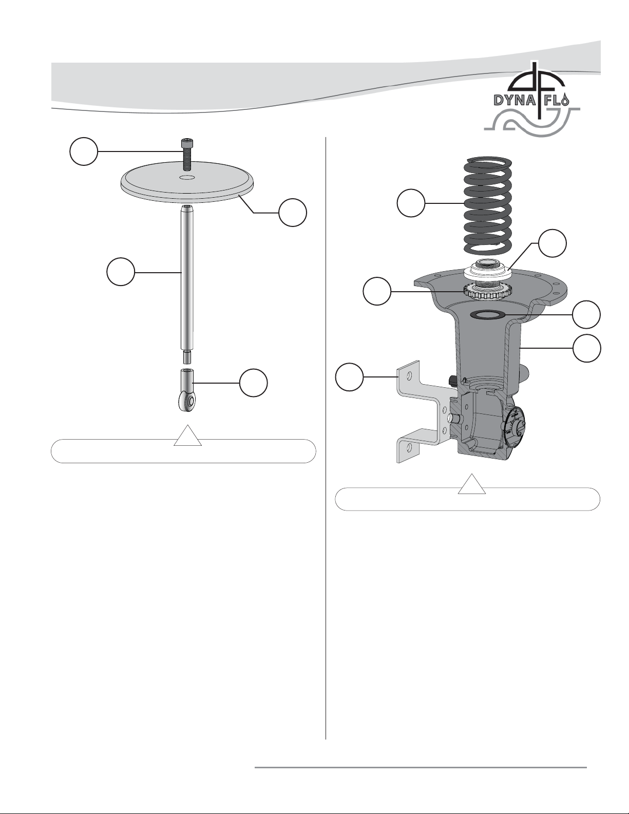
Figure 14 Diaphragm/Rod Plate Disassembly
ACTUATOR DISASSEMBLY (Continued)
SPRING / ADJUSTER / SEAT DISASSEMBLY
1 Remove the spring (Key 14) from the actuator housing
(Key 1).
2 Remove the spring seat (Key 13) and spring adjuster (Key
12). Separate the spring seat from the spring adjuster if
necessary.
3 Remove the thrust washer (Key 11).
14
13
12
11
1
3
Figure 15 Spring / Adjuster / Seat Removal
3 Using split-ring pliers, remove the retaining ring (Key 9)
from the hub (Key 5). Slide the travel scale (Key 8) off
the hub.
4 Remove the machine screws (Key 7) from the hub (Key
5) and remove the travel indicator (Key 6).
4 Inspect all parts for damage or wear, replace or repair
parts as necessary.
MOUNTING YOKE / HUB REMOVAL
1 Remove the cap screws (Key 4) and mounting yoke (Key
3).
2 Remove the machine screws (Key 10) and slide the hub/
travel scale assembly (Keys 5, 6, 7, 8, & 9) out of
the actuator housing (Key 1).
Dyna-Flo Control Valve Services Ltd.
Phone: 780 • 469 • 4000 Toll Free: 1 • 866 • 396 • 2356 Fax: 780 • 469 • 4035 Website: www.dynafl o.com
BUSHING INSPECTION / REMOVAL
1 Inspect the bushings (Key 2) in the actuator housing (Key
1).
2 If the bushings look worn or damaged and need to be
replaced, carefully press the bushings out of the housing
from the inside pushing out.
P-DFR1M0918A
13
Page 14
Model DFR 026 Rotary Actuator
Operation, Parts, and Instruction Manual
293
4
2
Figure 16 Mounting Yoke Removal
ACTUATOR ASSEMBLY
Before You Begin:
• The Assembly section of this manual assumes that the
actuator has been completely disassembled prior to
assembly.
• Read the General and Scope section of this manual (Page 2).
• Read Safety Caution (Page 2).
• Use safe work practices and lock out procedures.
Special Tools Required:
• Flat-head screwdriver or fl at-bladed tool.
1
• Regulated air supply (to stroke the actuator).
• Vise grips.
• Split-ring pliers.
• 5/16” socket bit.
Lubricants Required:
• Permatex® Nickel Anti-Seize or equivalent (Key A)
• Lubriplate® No. 105 Grease or equivalent (Key C)
• Fluid Film® (Key D)
• Loctite® 242® (Key E)
Note: These assembly instructions assume that the control
valve is still installed in the pipeline. If the control valve has
been removed from the pipeline, make sure that the valve is
placed securely on a fl at work surface or clamping device that
9 10
can support the combined weight of the control valve/actuator
assembly.
6
BUSHING INSTALLATION
1 If the bushings (Key 2) have been removed from the
housing (Key 1) insert new bushings. Bushings may need
to be pressed into place.
MOUNTING YOKE / HUB ASSEMBLY
2
8
5
7
1
Figure 17 Hub Removal
Dyna-Flo Control Valve Services Ltd.
Phone: 780 • 469 • 4000 Toll Free: 1 • 866 • 396 • 2356 Fax: 780 • 469 • 4035 Website: www.dynafl o.com
1 Refer to Figure 10 and Table 2, determine the desired
mounting style and orientation. Install the mounting yoke
(Key 3) onto the actuator housing (Key 1) with the cap
screws (Key 4). Refer to Table 4 for cap screw torque
values.
2 Install the travel indicator (Key 6) onto the hub (Key 5)
using the machine screws (Key 7).
P-DFR1M0918A
14
Page 15
Model DFR 026 Rotary Actuator
Operation, Parts, and Instruction Manual
3
29
10
9 7
4
2
8
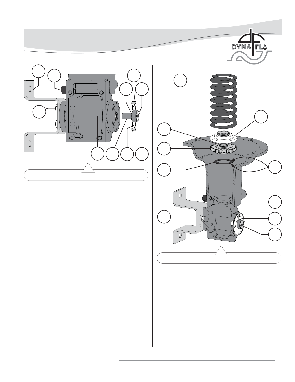
Figure 18 Hub Installation
ACTUATOR ASSEMBLY (Continued)
MOUNTING YOKE / HUB ASSEMBLY (Continued)
3 Slide the travel scale (Key 8) onto the hub (Key 5) and
secure it in place using the retaining ring (Key 9) and
split-ring pliers.
14
13
A
12
65
11
C
1
3
8
4 Install the hub/travel scale assembly (Keys 5, 6, 7, 8, &
9) onto the actuator housing (Key 1) using the machine
screws. Note: The hub and travel indicator can be rotated
into the proper orientation at any time before the valve
shaft is installed.
Figure 19 Spring / Adjuster / Seat Assembly
SPRING / ADJUSTER / SEAT ASSEMBLY
1 Lubricate the thrust washer (Key 11) with Lubriplate® No.
105 Grease (Key C) and install it into the actuator housing
(Key 1).
2 Apply Permatex® Nickel Anti-Seize (Key A) to the threads
of the spring adjuster (Key 12). Thread the spring seat
(Key 13)all the way onto the spring adjuster.
3 Install the spring adjuster/spring seat assembly (Keys 12 &
13) over top of the thrust washer (Key 11) inside the
actuator housing (Key 1).
4 Install the spring (Key 14) onto the spring seat (Key 13)
inside the actuator housing (Key 1).
Dyna-Flo Control Valve Services Ltd.
Phone: 780 • 469 • 4000 Toll Free: 1 • 866 • 396 • 2356 Fax: 780 • 469 • 4035 Website: www.dynafl o.com
DIAPHRAGM ROD/PLATE ASSEMBLY
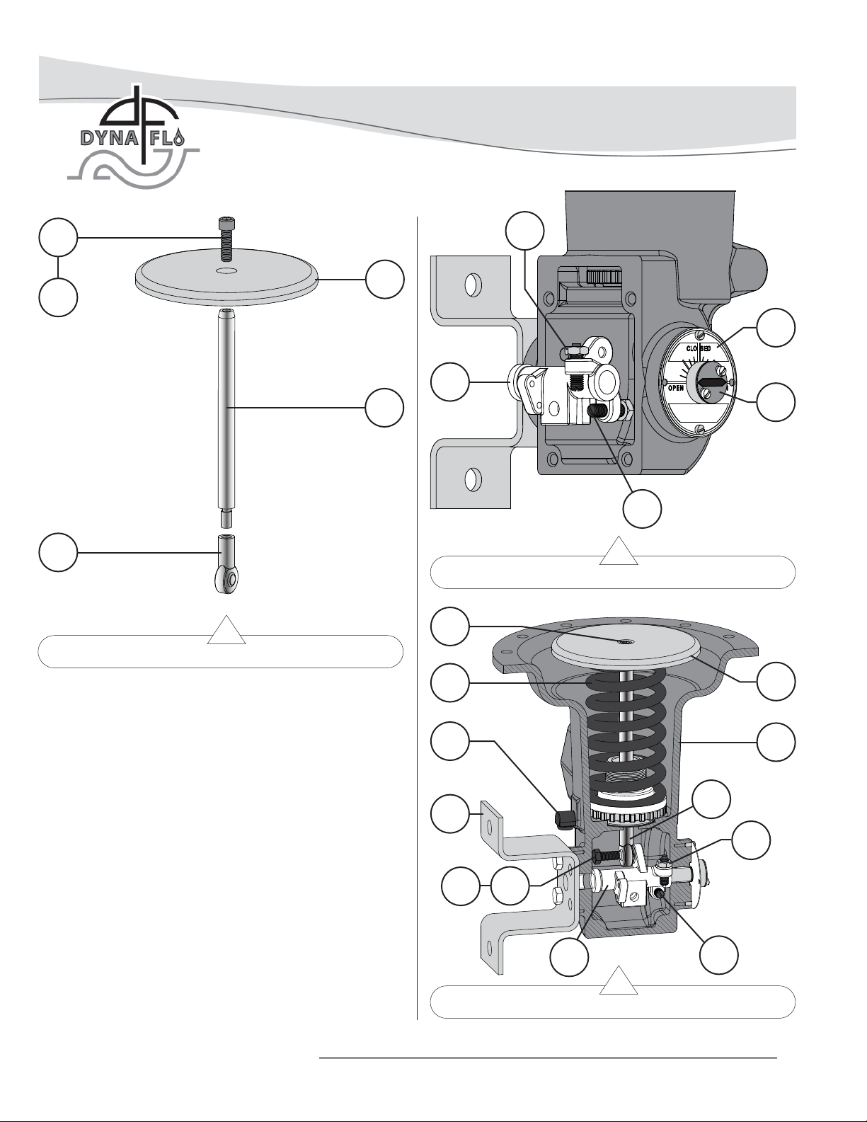
1 If the rod end bearing (Key 15) was removed from the
diaphragm rod (Key 16), thread the diaphragm rod back
into the rod end bearing.
2 Apply anti-seize compound (Key A) to the threads of the
socket-head cap screw (Key 18).
3 Attach the diaphragm plate (Key 17) to the diaphragm
rod (Key 16) using the socket-head cap screw (Key 18)
and a 5/16” socket bit.
4 Torque the socket-head cap screw (Key 18) to the value
listed in Table 4.
P-DFR1M0918A
6
15
Page 16
Model DFR 026 Rotary Actuator
Operation, Parts, and Instruction Manual
18
A
15
17
16
21
8
19
6
20
Figure 21 Lever Assembly / Installation
18
Figure 20 Diaphragm Plate/Rod Assembly
14
ACTUATOR ASSEMBLY (Continued)
LEVER ASSEMBLY AND INSTALLATION
1 If the set screws (Key 20) and jam nuts (Key 21) were
removed from the lever (Key 19), re-install them as shown
in Figure 21.
2 Place the lever assembly (Keys 19, 20, & 21) inside the
actuator housing (Key 1) as shown in Figure 21.
3 Place the diaphragm plate assembly (Keys 15, 16, 17, &
18) into the actuator housing (Key 1). Be aware of the
orientation of the rod end bearing (Key 15), the hole in the
rod end bearing should be in alignment with the hole in the
lever (Key 19). Refer to Figure 22.
4 Apply Loctite® 242® (Key E) to the threads of the cap
screw (Key 22). Using the cap screw, connect the rod end
bearing (Key 15) to the lever (Key 19). Torque the cap
screw to the torque value listed in Table 4.
Dyna-Flo Control Valve Services Ltd.
Phone: 780 • 469 • 4000 Toll Free: 1 • 866 • 396 • 2356 Fax: 780 • 469 • 4035 Website: www.dynafl o.com
29
3
15
E
22
19
Figure 22 Lever Installation
P-DFR1M0918A
17
1
21
20
16
Page 17
Model DFR 026 Rotary Actuator
Operation, Parts, and Instruction Manual
ACTUATOR ASSEMBLY (Continued)
24
25
23
17
DIAPHRAGM CASING ASSEMBLY
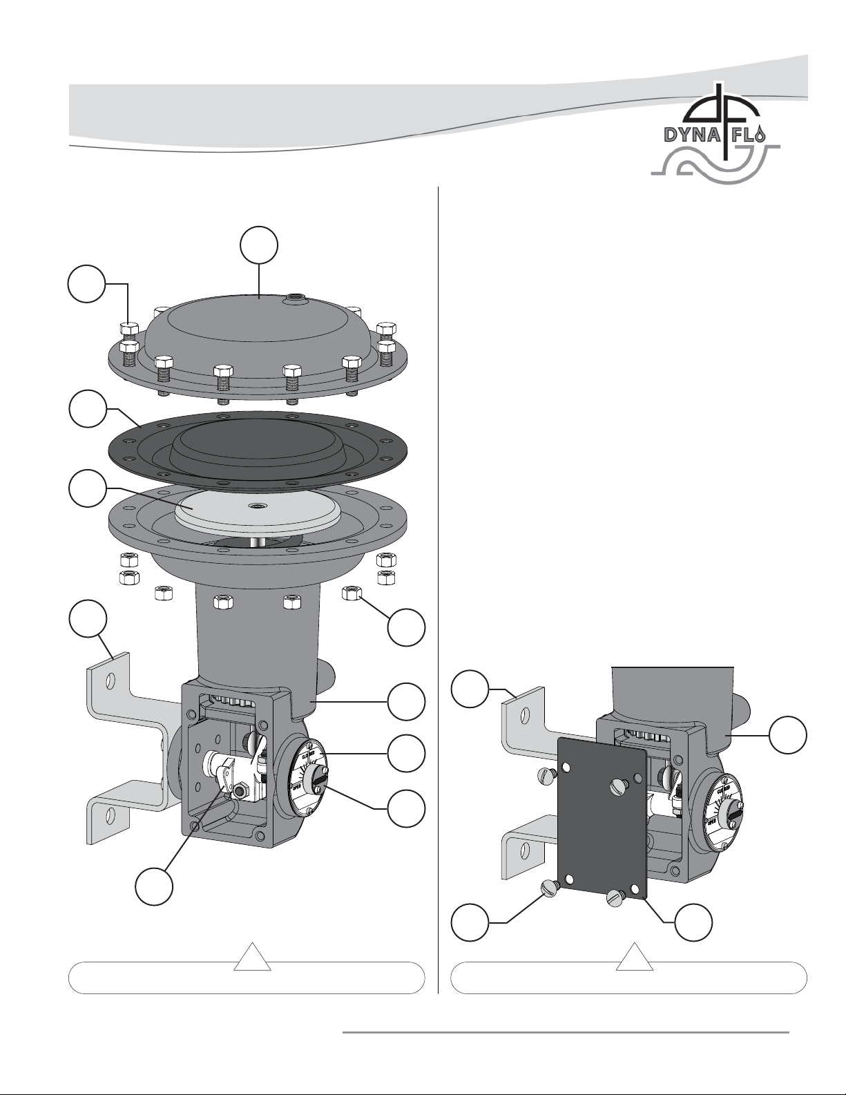
1 Place the diaphragm (Key 23) over the diaphragm plate
(Key 17), align the holes in the diaphragm with the holes in
the actuator housing (Key 1).
2 Set the upper diaphragm casing (Key 24) on top of the
actuator housing (Key 1), align the holes. Note: If
a Top-Mounted Handwheel is being used, it is advised that
the position of the stem (Key 103) be adjusted so that the
device will place no downward pressure on the actuator
spring (Key 14).
3 Install the cap screws (Key 25) through the diaphragm
casing (Keys 24).
4 Install the hex nuts (Key 26) and tighten them evenly in
an alternating crisscross pattern to the torque specifi cation
listed in Table 4.
5 Mount the actuator to the valve before performing the
SPRING ADJUSTMENT - Initial Set (Page 7).
ACCESS PLATE INSTALLATION
3
26
1 Install the access plate (Key 27) using the machine screws
(Key 28).
3
1
1
8
6
19
28 27
Figure 23 Diaphragm Casing Assembly Figure 24 Access Plate Installation
Dyna-Flo Control Valve Services Ltd.
Phone: 780 • 469 • 4000 Toll Free: 1 • 866 • 396 • 2356 Fax: 780 • 469 • 4035 Website: www.dynafl o.com
P-DFR1M0918A
17
Page 18
Model DFR 026 Rotary Actuator
Operation, Parts, and Instruction Manual
PRINCIPLES OF OPERATION AND
ADJUSTMENT – HANDWHEEL
TOP-MOUNTED HANDWHEEL
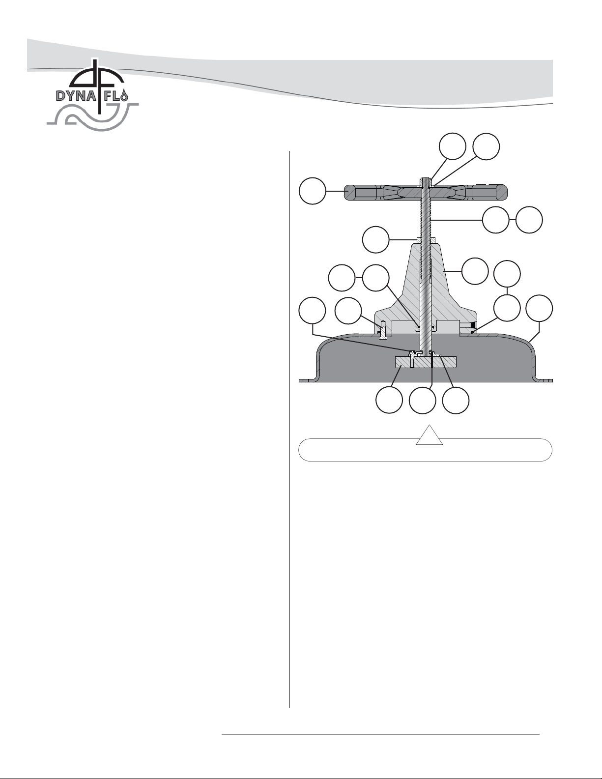
DFR Top-Mounted Handwheel assemblies are attached to a
modifi ed upper diaphragm casing (Key 24A) using cap screws
(Key 109). To lock the handwheel in position, tighten the lock
nut (Key 104) into the body (Key 105) of the handwheel.
To compress the spring (Key 14) and move diaphragm
rod (Key 16) down:
Turning the handwheel (Key 102) clockwise into the upper
diaphragm casing (Key 24A) forces the pusher plate
(Key 112) onto the diaphragm (Key 23) and diaphragm
plate (Key 17) to compress the spring.
To decompress the spring (Key 14) and allow diaphragm
rob (Key 16) to move up:
Turning the handwheel (Key 102) counterclockwise away
from the upper diaphragm casing (Key 24A) allows the
actuator spring to decompress which moves the diaphragm
plate (Key 17) and diaphragm rod (Key 16) upward.
Note: If the valve is push-down-to-close, full valve opening can
be restricted by adjusting the handwheel to the desired
position.
102
111
109
104
107B
112
100
110113
105
101
103
B
108
C
24A
If the valve is push-down-to-open, full valve closing can be
restricted by adjusting the handwheel to the desired position.
Figure 25 DFR Top-Mounted Handwheel
MAINTENANCE - TOP-MOUNTED
MAINTENANCE - TOP-MOUNTED
HANDWHEELS
Maintenance should be performed if actuator loading pressure
appears to be leaking from either the handwheel or travel stop.
It is possible that either of the o-rings (Keys 107 & 108) need
to be replaced.
Before disassembling the handwheel or travel stop to replace
o-rings, perform the following steps:
• Lubricate the threads of the stem (Key 103) with white
petroleum grease, stroke the device a couple times after
application.
Dyna-Flo Control Valve Services Ltd.
Phone: 780 • 469 • 4000 Toll Free: 1 • 866 • 396 • 2356 Fax: 780 • 469 • 4035 Website: www.dynafl o.com
HANDWHEELS O-RING REPLACEMENT
Before You Begin:
• Read the General and Scope section of this manual (Page 2).
• Read Safety Caution (Page 2).
• Use safe work practices and lock out procedures.
• Disconnect supply lines (air or gas), electric power, or control
signal to the actuator. Sudden movement of actuator can
cause damage or injury, make sure actuator will not operate.
• Vent any pneumatic actuator loading pressure.
• Relieve process pressure and drain the process fl uid from up
and down stream of valve.
• Be aware of potentially hazardous process material that may
be present in-line and in-valve. Isolate the valve from
process pressure. Use a bypass or block valve if necessary,
or completely shut off the process. Relieve internal valve
pressure (refer to the appropriate valve instruction manual).
P-DFR1M0918A
18
Page 19

Model DFR 026 Rotary Actuator
Operation, Parts, and Instruction Manual
Special Tools Required:
• Flat-head screwdriver or fl at-bladed tool.
Lubricants Required:
• Dow Corning Molykote® 111 or equivalent (Key B)
• Lubriplate® No. 105 Grease or equivalent (Key C)
1 Rotate the handwheel counterclockwise and remove any
spring tension applied by the handwheel.
2 Relieve any actuator spring (Key 14) compression by
turning the spring adjuster (Key 12) clockwise until it
stops turning. Refer to Step 2 & 3 of the Casing
Disassembly Section.
3 Refer to the Actuator Disassembly – Casing Disassembly
Steps 1, 3 & 4 and remove the upper diaphragm casing
(Key 24A).
4 Separate the handwheel assembly from the upper
diaphragm casing (Key 24A) by removing the cap screws
(Key 109).
5 Loosen the lock nut (Key 104).
6 Remove the hex nut (Key 100), fl at washer (Key 101), and
handwheel (Key 102).
7 Rotate the stem (Key 103) clockwise out of the body (Key
105).
8 Remove and replace the o-rings (Keys 107 & 108).
Lubricate the new o-rings with sDow Corning Molykote
111 (Key B).
9 Re-assemble the handwheel and diaphragm casing. Refer
to the Actuator Assembly section (Page 11).
10 Perform spring adjustment.
®
Dyna-Flo Control Valve Services Ltd.
Phone: 780 • 469 • 4000 Toll Free: 1 • 866 • 396 • 2356 Fax: 780 • 469 • 4035 Website: www.dynafl o.com
P-DFR1M0918A
19
Page 20
Model DFR 026 Rotary Actuator
Operation, Parts, and Instruction Manual
25
14
4
22
12
17
29
2
18
13
11
15
10
7
26
23
16
24
12
1817
13
8
6
11
15
25
1
14
27
28
21
20
5
9
3
Dyna-Flo Control Valve Services Ltd.
Phone: 780 • 469 • 4000 Toll Free: 1 • 866 • 396 • 2356 Fax: 780 • 469 • 4035 Website: www.dynafl o.com
19
19A
2
20
20
21
19A
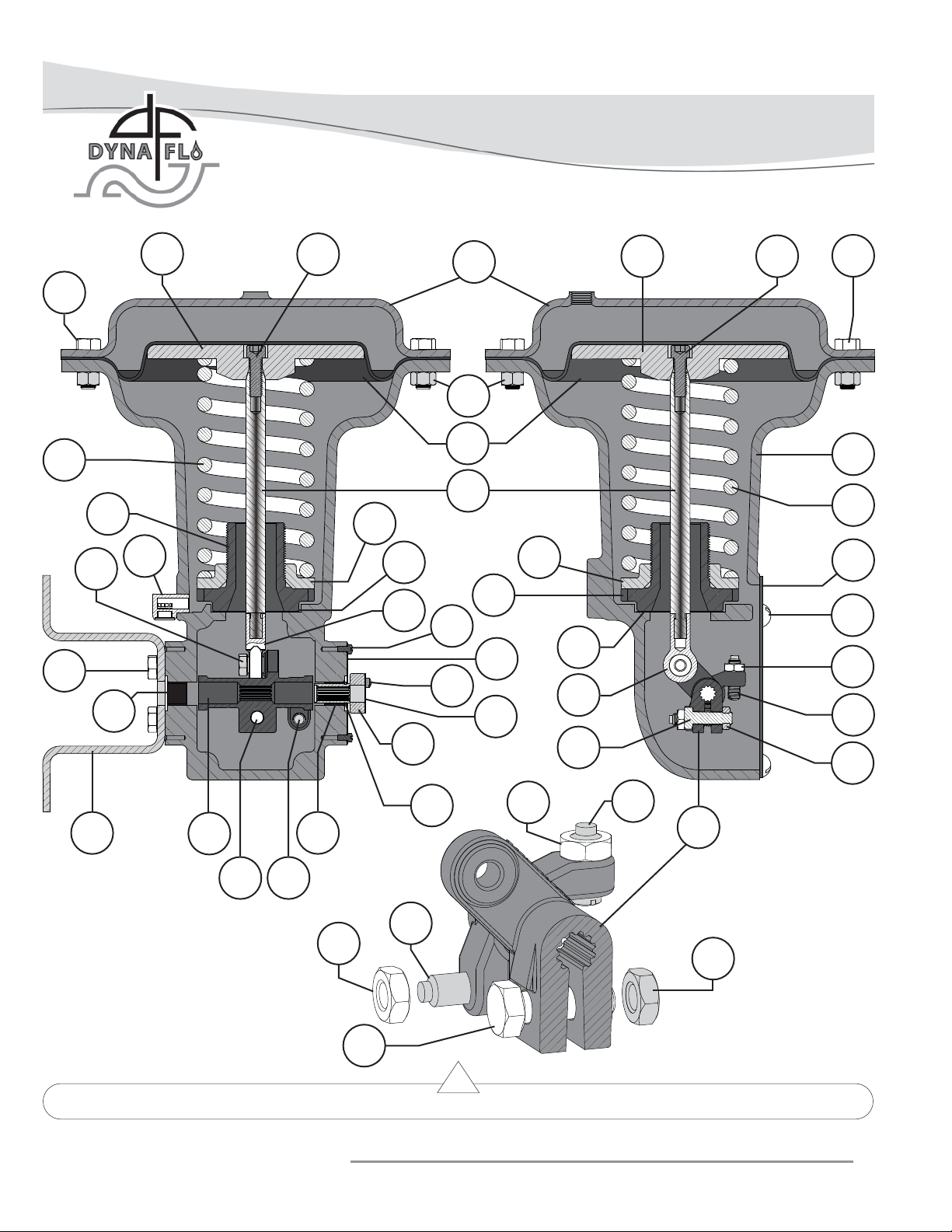
Figure 26 Actuator Cross Section
21
19A
20
19
19B
P-DFR1M0918A
19B
20
Page 21
Model DFR 026 Rotary Actuator
Operation, Parts, and Instruction Manual
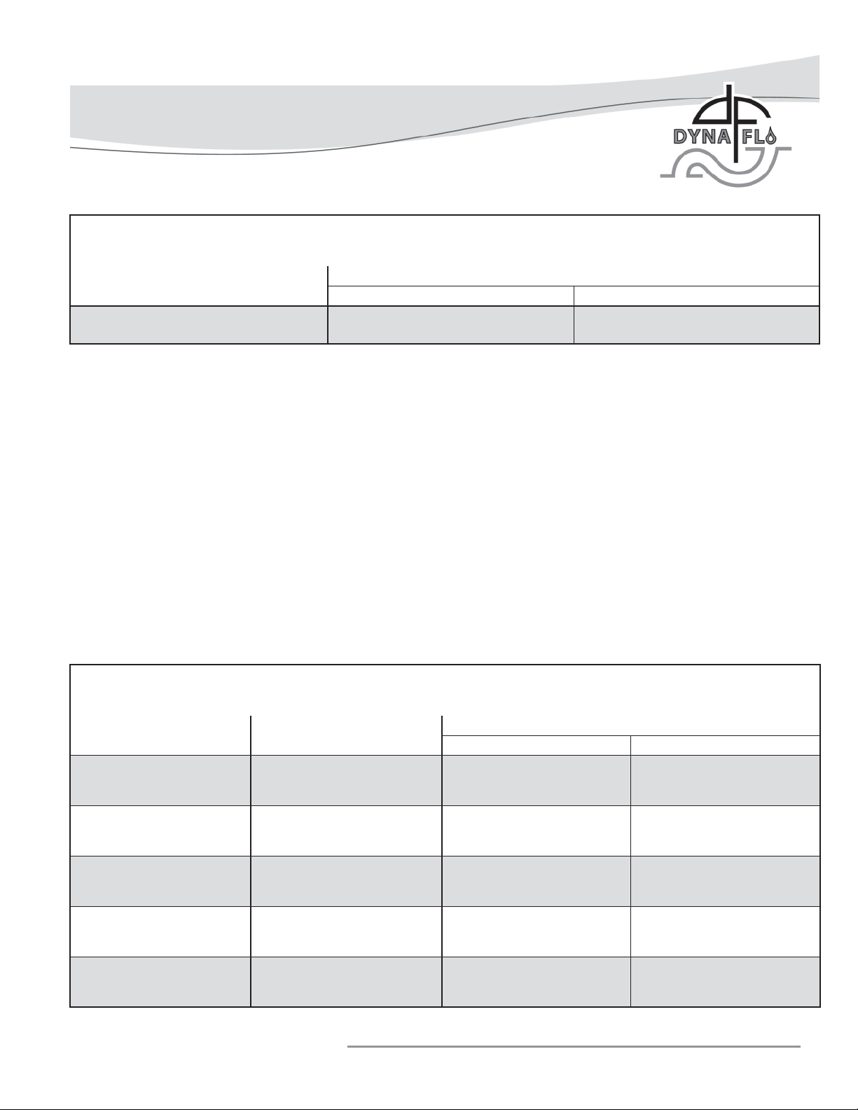
Torque Specifi cations for Valve Mounting Bolts (Key 30)
Table 3
Valve Shaft Diameter
1/2 Inch &
5/8 Inch x 1/2 Inch
DFR Torque Specifi cations
Mounting Bolts
lbf-ft N
65 88
•m
Table 4
Key Bolt Size
4 3/8”-16 25 34
18 5/16”-18 16 22
21 5/16”-18 20 27
22 5/16”-18 16 22
25 3/8”-24 20 27
lbf-ft N•m
Dyna-Flo Control Valve Services Ltd.
Phone: 780 • 469 • 4000 Toll Free: 1 • 866 • 396 • 2356 Fax: 780 • 469 • 4035 Website: www.dynafl o.com
Torque
P-DFR1M0918A
21
Page 22
Model DFR 026 Rotary Actuator
Operation, Parts, and Instruction Manual
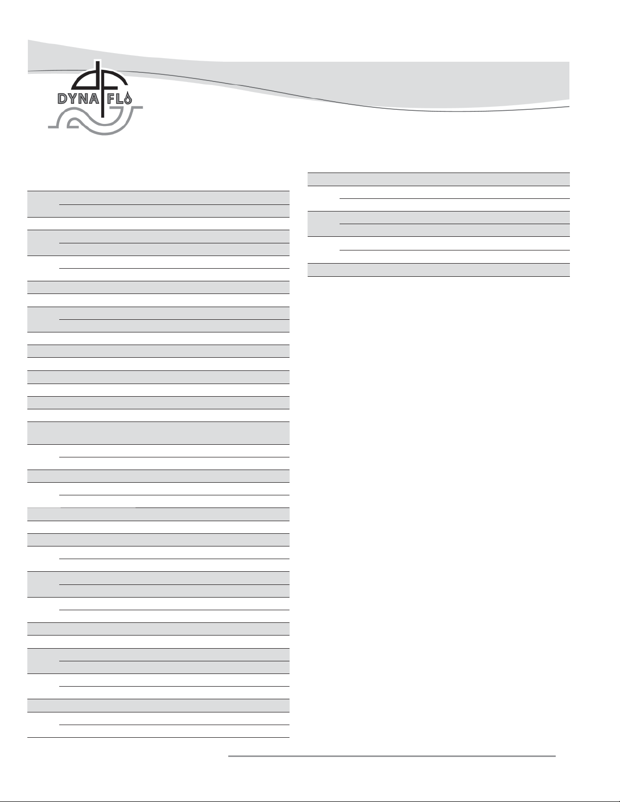
Parts
Key Description Part Number
1 Housing Assembly, Cast Iron
Includes Bushings (Key 2) 46A4670X01D
2 Bushing, Bronze, 2 Required DFR0260001D
3 Mounting Yoke, Steel
1/2 inch shaft 36A4658X01D
4 Cap Screw, Mounting Yoke
4 Required
5 Hub, Aluminum 26A4676X01D
6 Travel Indicator, SST 28A8529X01D
7 Machine Screw, Travel Indicator
SST, 4 Required 1V74353522D
8 Travel Scale, SST 28A8527X01D
9 Retaining Ring, Steel 1A90292899D
10 Machine Screw, Travel Scale Refer to Key 7
11 Thrust Washer, Steel 16A4681X01D
12 Spring Adjuster, Cast Iron 26A4665X01D
13 Spring Seat, Zinc Plated Steel 26A4664X01D
14 Spring Refer to Table 5
15
16 Diaphragm Rod Assembly, Zinc Plated Steel
17 Diaphragm Plate, Cast Iron 33B9686X01D
18 Socket Head Cap Screw, Diaphragm Plate
19 Lever, WCC 34B8600X01D
19A Cap Screw, Lev er, Zinc Plated Steel H5CZ516.100
19B Jam Nut, Lever, Zinc Plated Steel NHJCZ516
20 Set Screw, Travel Stop,
21 Jam Nut, Travel Stop
22 Cap Screw, Lever/Diaphragm Rod H5CZ516.034
23 Diaphragm, Nitrile 26A4668X01D
24 Upper Diaphragm Casing, Steel DF10408X01D
25 Cap Screw, Diaphragm Casing,
26 Hex Nut, Diaphragm Casing
27 Access Plate, Steel 26A4655X01D
28 Machine Screw, Access Plate
Rod End Bearing, Zinc Plated
Steel
Includes Rod End Bearing 26A4651X01D
Steel SCC516.100
18-8 Steel, 2 Required 16A4667X02D
Zinc Plated Steel, 2 Required NHJC516
Zinc Plated Steel
Zinc Plated Steel, 12 Required H5FZ38.114
Zinc Plated Steel, 12 Required NHFZ38
Zinc Plated Steel, 4 Required 1C12252898D
H5CZ38.100
Refer to Key 16
Key Description Part Number
29 Elbow Vent, Plastic Y602-12D
30 Mounting Bolt, Actuator / Valve, Zinc Plated Steel
Mounting bolts are included with the valve assembly.
31 Lockwasher, Actuator / Valve, Zinc Plated Steel
lockwashers are included with the valve assembly.
32 Hex Nut, Mounting Bolt, Zinc Plated Steel
Hex nuts are included with a 570 valve assembly.
33 Nameplate NAMEXSRACTD
Dyna-Flo Control Valve Services Ltd.
Phone: 780 • 469 • 4000 Toll Free: 1 • 866 • 396 • 2356 Fax: 780 • 469 • 4035 Website: www.dynafl o.com
P-DFR1M0918A
22
Page 23
Model DFR 026 Rotary Actuator
Operation, Parts, and Instruction Manual
PARTS - DFR Handwheel Parts List
KEY PART DESCRIPTION PART NUMBER
100 NYLOCK HEX NUT DFO30109X1D
101 FLAT WASHER DF060110X1D
102 HANDWHEEL DFO40106X1D
103 STEM DFR40102X1D
104 LOCK NUT DFO60107X1D
105 BODY DFR40201X1D
107 O-RING, STEM 1D23750699D
108 O-RING, BODY/CASING 1D26730699D
109 CAP SCREW, BODY/CASING (6 REQUIRED) 1A36842405D
110 PUSHER PLATE RETAINER DFO60111X1D
111 SOCKET HEAD CAP SCREW, PUSHER PLATE RETAINER (3 REQUIRED) DFO20114X1D
112 PUSHER PLATE DFO60103X1D
113 SPRING PIN DFO60115X1D
24A UPPER DIAPHRAGM CASING DF10410X01D
DFR Spring (Key 6) Information
Casing Pressure Initial Spring Compression
Push-Down-To-Open
Psig Bar
0 - 18 0 - 1.2 3.9 27 3.0 21 16A4660X01D
0 - 33 0 - 2.3 6.8 47 3.0 21 16A4659X01D
(Fail Closed)
Psig kPa Psig kPa
Push-Down-To-Close
(Fail Open)
Part Number
Parts Ordering
Whenever corresponding with Dyna-Flo about a DFR actuator, refer to the nameplate (Key 33)
for the serial number of the unit. Please order by the complete part number (as given in the
following parts list) of each part required.
Table 5
Dyna-Flo Control Valve Services Ltd.
Phone: 780 • 469 • 4000 Toll Free: 1 • 866 • 396 • 2356 Fax: 780 • 469 • 4035 Website: www.dynafl o.com
P-DFR1M0918A
23
Page 24
Model DFR 026 Rotary Actuator
MODEL NUMBERING SYSTEM
SAMPLE PART NUMBER: DFR-026-C-04S1-C-RA1
026 SIZE 026
C FAIL CLOSED O FAIL OPEN N NOT APPLICABLE
- DFPS-01 (STANDARD PAINT) 2 DFPS-02 (SEVERE SERVICE PAINT)
3 DFPS-03 (HI-TEMP PAINT)
SHAFT CONNECTION SIZE
04 1/2 INCH
SHAFT CONNECTION TYPE
S SPLINED (STANDARD)
OPERATING PRESSURE RANGE (PSIG)
1 0 - 18 3 0 - 33
- STANDARD S SST BOLTING
SPRING RANGE (SEE TABLE 7)
C 0-18 PSIG RANGE, 0-33 PSIG RANGE H 0-33 PSIG RANGE
HANDWHEELS / TRAVEL STOPS
- NONE (STANDARD) T TOP-MOUNTED HANDWHEEL
R RIGHT HAND MOUNT L LEFT HAND MOUNT
A STYLE A, B, C, D - REFER TO FIGURE 10
1 POSITION A, B, C, D - REFER TO FIGURE 10 (RIGHT HAND POSITION 1 IS STANDARD)
N NOT APPLICABLE
ACTUATOR
FAIL POSITION
PAINT
OPTIONS
MOUNTING
026
C
-
04
S
1
-
C
-
RA1
DFR - - - - -
Our Commitment to Quality
Dyna-Flo is committed to continuous improvement. While all efforts have been made to ensure the accuracy of the content in
this document, modifi cations or improvements to the information, specifi cations, and designs may occur at any time without
notice. This document was published for informational purposes only, and does not express or imply suitability, a warranty,
or guarantee regarding the products or services described herein or their use or applicability.
Neither Dyna-Flo Control Valve Services Ltd., nor any of their affi liated entities assumes responsibility for the selection, use
and maintenance of any product. Responsibility for selection, use and maintenance of any product remains with the purchaser
and end-user.
Dyna-Flo Control Valve Services Ltd.
Phone: 780 • 469 • 4000 Toll Free: 1 • 866 • 396 • 2356 Fax: 780 • 469 • 4035 Website: www.dynafl o.com
P-DFR1M0918A
24
 Loading...