

Page 1
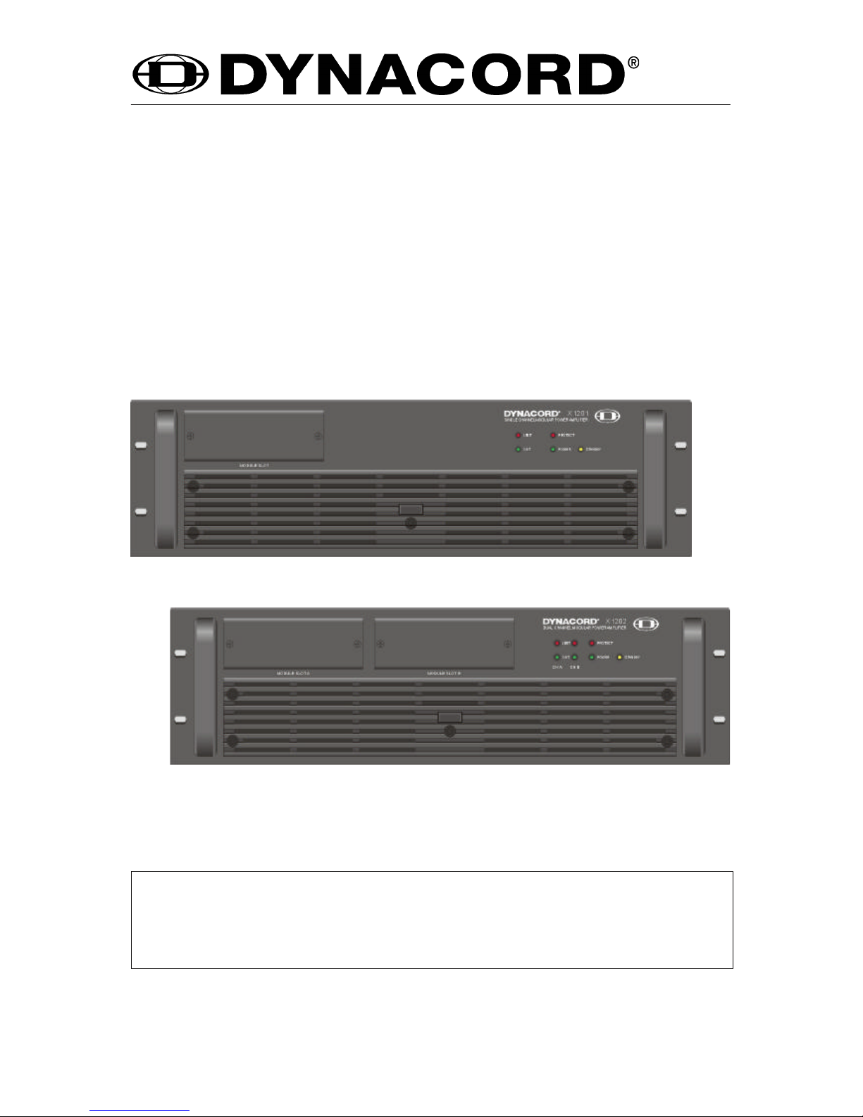
X1201 / X 1202
MODULAR POWER AMPLIFIER
OWNER’S MANUAL
Page 2
The lightning flash with arrowhead symbol, within an
equilateral triangle is intended to alert the user to the
presence of uninsulated “dangerous voltage” within the
product’s enclosure that may be of sufficient magnitude to
constitute a risk of electric shock to persons.
The exclamation point within an equilateral triangle is
intended to alert the user to the presence of important
operating and maintance (servicing) instructions in the
literature accompanying the appliance.
1. Read these instructions.
2. Keep these instructions.
3. Heed all warnings.
4. Follow all instructions.
5. Do not use this apparatus near water.
6. Clean only with a damp cloth.
7. Do not block any of the ventilation openings.
Install in accordance with the manufactures instructions.
8. Do not install near any heat sources such as radiators, heat registers, stoves, or other apparatus that produce heat.
9. Only use attachments/accessories specified by the manufacturer.
10. Refer all servicing to qualified service personnel. Servicing is required when the apparatus has been
damaged in any way, such as power-supply cord or plug is damaged, liquid has been spilled or objects have fallen
into the apparatus, the apparatus has been exposed to rain or moisture, does not operate normally, or has
been dropped.
For US and CANADA only:
Do not defeat the safety purpose of the grounding-type plug. A grounding type plug has two blades and a third grounding prong.
The wide blade or the third prong are provided for your safety. When the provided plug does not fit into your outlet, consult an
electrican for replacement of the absolete outlet.
1. Security regulations as stated in the EN 60065 (VDE 0860 / IEC 65) and the CSA E65 - 94 have to be obeyed when
servicing the appliance.
2. Use of a mains separator transformer is mandatory during maintenance while the appliance is opened, needs to be
operated and is connected to the mains
3. Switch off the power before retrofitting any extensions, changing the mains voltage or the output voltage.
4. The minimum distance between parts carrying mains voltage and any accessible metal piece (metal enclosure),
respectively between the mains poles has to be 3 mm and needs to be minded at all times.
The minimum distance between parts carrying mains voltage and any switches or breakers that are not connected
to the mains (secondary parts) has to be 6 mm and needs to be minded at all times.
5. Replacing special components that are marked in the circuit diagram using the security symbol (Note) is only permissible
when using original parts.
6. Altering the circuitry without prior consent or advice is not legitimate.
7. Any work security regulations that are applicable at the location where the appliance is being serviced have to be strictly
obeyed. This applies also to any regulations about the work place itself.
8. All instructions concerning the handling of MOS - circuits have to be observed.
Note:
IMPORTANT SERVICE INSTRUCTIONS
CAUTION: These servicing instructions are for use by qualified personnel only. To reduce the risk of
electric shock, do not perform any servicing other than that contained in the Operating
Instructions unless you are qualified to do so. Refer all servicing to qualified service
personnel.
IMPORTANT SAFETY INSTRUCTIONS
12
Page 3

X-Amps
First of all, we would like to take the opportunity to thank you for and congratulate you on buying the
DYNACORD X-Amp Series power amplifiers.
X-Amps - a modular power amplifier concept and the most flexible solution for any mobile and permanent
installation application. The modular architecture of the X-Amps allows flexible selection of filter / signal
processor as well as input and output modules. This provides the possibility to easily include X-Amps
power amplifiers into basically any existing and most of all any future application, using principally any
connection technique. Factory-shipped, the X-Amps are equipped with an input module Xi-11 (XLR-type
inputs with thru-connectors) and an output module Xo-1 (SPEAKON-type connectors). The front slots of
the X-Amps are covered with blind panels. These slots are meant for including filter or signal processor
modules into the signal path. Next to generic modules for general use, cabinet-pertinent modules for
DYNACORD V-Systems loudspeakers are available, which in regard to their response and dynamic
capacity optimally match the equalization of the V-Systems loudspeaker components.
The use of front modules makes it easy to establish high quality and yet cost effective multi-way systems
while cabling of the entire system is drastically reduced.
The power amplifiers X1201 providing 1 x 1200W into 4 ohms and X1202 providing 2 x 600W into 4 ohms
unite outstanding audio performance, highest reliability, and security.
The gapless protection concept not only prevents the power amplifiers from being damaged but also the
connected loudspeaker systems. This extensive protection circuitry includes dynamic limiters, DC/HF
protection, Back-EMF protection, inrush current limiter, short circuit protection, thermal brain circuit, and
of course the protection against thermal overload of the power stage transistors and the transformers.
During “soft start”, delayed switching the power outputs is performed via relays.
Thermal stability is guaranteed through extremely low-noise, 3-stage fans.
The air circulation is front-to-rear, allowing trouble-free operation even in smaller power amplifier rack
systems.
The embodied comparators constantly monitor the power amp’s input and output signals, and control the
integrated limiters whenever non-linearity is detected, thus protecting the connected loudspeaker systems
against overload and power amplifier clipping. The overall response of the X-Amps is simply extraordinary.
Using widely dimensioned power supplies with low-loss toroidal transformers provide additional headroom
way above the stated nominal power output capacity. The power amplifiers do not employ V/I-FoldbackLimiters, which allows to drive even complex loads with phase angles of up to 90° without a problem.
Also the mechanic construction and manufacturing guarantee highest precision. The robust and highly
rigid steel chassis is meant to survive the extensive wear of touring applications. The easily readable
LED-display provides quick information about the power amplifier’s operational state. Ready-mode, signal
presence, and the activation of limiters or of one of the protection functions are indicated for both channels
individually. All X-Amp Series power amplifiers are capable of handling loads down to 2 ohms.
This owner’s manual holds information about many other features of the X-Amp Series power amplifiers.
Therefore, carefully reading the entire manual is strongly recommended, so that you are able to get the
best performance from your new DYNACORD X-Amp Series power amplifier.
CONTENTS
Description . . . . . . . . . . . . . . . . . . . . . . . . . . . . . . . . . . . . . . . . . . . . . . . . . . . . . . . . . . . 13
X-Amp System . . . . . . . . . . . . . . . . . . . . . . . . . . . . . . . . . . . . . . . . . . . . . . . . . . . . . . . . 14
Installation. . . . . . . . . . . . . . . . . . . . . . . . . . . . . . . . . . . . . . . . . . . . . . . . . . . . . . . . . . . . 17
Front Panel . . . . . . . . . . . . . . . . . . . . . . . . . . . . . . . . . . . . . . . . . . . . . . . . . . . . . . . . . . . 18
Rear Panel . . . . . . . . . . . . . . . . . . . . . . . . . . . . . . . . . . . . . . . . . . . . . . . . . . . . . . . . . . . 20
Specifications . . . . . . . . . . . . . . . . . . . . . . . . . . . . . . . . . . . . . . . . . . . . . . . . . . . . . . . . . 32
Block diagram . . . . . . . . . . . . . . . . . . . . . . . . . . . . . . . . . . . . . . . . . . . . . . . . . . . . . . . . . 34
Dimensions. . . . . . . . . . . . . . . . . . . . . . . . . . . . . . . . . . . . . . . . . . . . . . . . . . . . . . . . . . . 36
Warranty . . . . . . . . . . . . . . . . . . . . . . . . . . . . . . . . . . . . . . . . . . . . . . . . . . . . . . . . . . . . . 40
DESCRIPTION
13
Page 4

Most important performance features of your modular power amplifier system.
Open input and output architecture.
The design of the X-Amps’ input and output channels also follows the modular concept. The open
architectureallowsto comfortablymatchthe basicpoweramplifierstochanging operationalenvironments.
Therefore,differentXi-inputmodules as well asXo-outputmodulesare available. EvenifanX-Amppower
amplifier is finally configured, quick and comparably inexpensive modification is still possible. Whether
you change the output connection to system cabling, include input transformers, or replace complete
module groups, opening the power amplifier itself is not necessary.
Besides, all X-Amp Series power amplifiers are prepared for later remote control operation.
The modular structure including the input and output channels is future-oriented and therefore your
guaranty to be able to quickly react to advancements in connection or signal transmission techniques.
Additionally,it providesthepossibilitytomatch yourX-AmpSeries poweramplifiertospecificrequirements
at any time. This open input/output architecture ensures that your X-Amp is not going to belong to the
“scrap-heap”.
Module slots on the front panel.
The module slots on the front panel of the X-Amp Series power amplifier allow the insertion of Xm-filter
and-signal processor modules. A wide range of modules with individual functions are available. In this
way it is possible to integrate the signal processing which normally is realized through externalequipment
into the power amplifier. The advantage of handling things this way is quite obvious. Using Xm-modules
provides the opportunity to set up very compact sound reinforcement systems, individually matching a
particular application. Cable length and connections are reduced to their minimal amount. In the daily
work this improves operational reliability and lessens causes for faulty operation. Compared to conventional solutions using external equipment, the modular concept not only saves space but also money.
By placing the signal processing modules on the front panel of the power amplifier all indicators and
controls can be accessed at any time. The X-Amps provide comfortable control and monitoring from their
front panel.
X-Amp basic version - without front modules.
The input module Xi-11 and the output module Xo-1 are already installed when the appliance is shipped.
Of course, the X-Amp already works without front modules. The input sensitivity of the X-Amps is set to
a constant value of 1.4Veff (5dBu) with linear frequency response.
The basic version does not offer level controls, since their functionality is provided through the use of the
front modules or specific input modules, depending on the individual field of use.
X-Amp SYSTEM
14
Page 5
The modules
A wide variety of rear and front panel modules are available. Here, we cannot provide a listing of all
modules, since the X-Amp system, because of its open architecture, is continuously expanded, as a
reaction to the changing demands and requirements. Please contact your local dealer to get an updated
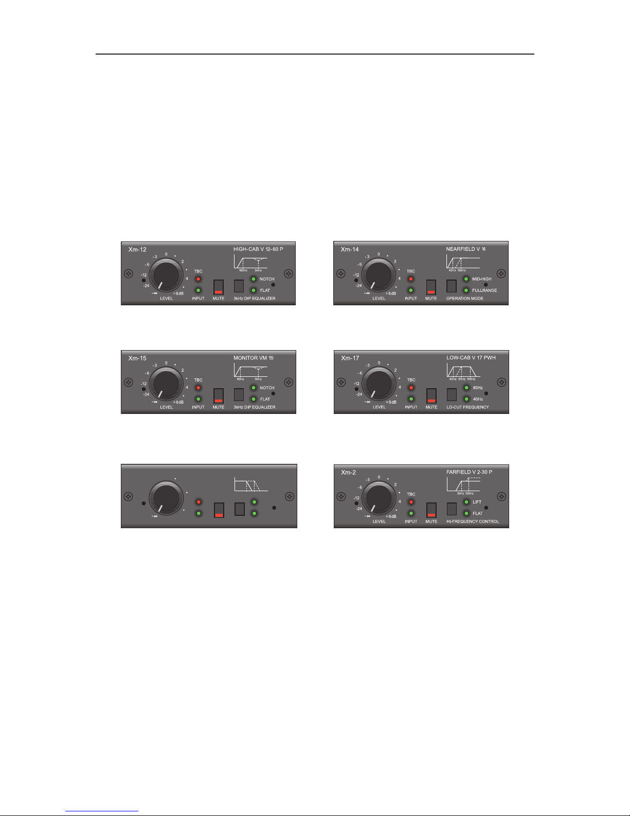
list of modules. As example, the following figures show some front modules for the DYNACORD
V-Systems. These are cabinet-pertinent modules which in response and dynamic capacity optimally
match the corresponding loudspeaker system. Thus, it is extremely easy to create optimally tuned,
high-quality multi-way systems, that are truly unique in audio performance, controllability and configuration. The Xm-modules are simply inserted into the frontal module slots of the X-Amps. The inserted
modules take over the control of all connected system components.
Additional adjustments are not necessary.
Example - DYNACORD V-Systems modules
Xm-12 Xm-14
Xm-15 Xm-17
Xm-18 Xm-2
LEVEL
+6dB
160Hz
80Hz
LO-PASS-FREQUENCYMUTE
4
2
-24
-12
-6
-3
0
TBC
SUBWOOFER V 18 PWH
80Hz 160Hz
Xm-18
INPUT
X-Amp SYSTEM
15
Page 6

Power amplifier design and protections
Quitesomeofthepoweramplifiertopology of the X-Amps derives from the meanwhilelegendaryLINEAR
PRECISION Series amplifiers. The X 1202 power amps offer a class A/B design, while the X 1201Single
Channel power amplifier is based on the “Grounded Bridge” technology. These power amplifier designs
have stated their capabilities several thousand times and therefore guarantee truly superb quality audio
performance and a maximum in operational stability. Optimizing the power amplifiers’ weight and thermal
behaviorwas possiblewithoutcompromisingtheiroutstandingoutput power capacity, dynamic response,
and transmission quality.
Compared to conventional designs, the X-Amp Series power amplifiers provide several details in
electronic circuitry, and protections design that normally are not perceptible for the user, and yet they are
responsible for the absolute stable operation of X-Amps. Here is a list of some of these functions:
Back-EMF Protection, to protect the output stage transistors against electrical energy that is returned
from reactive loads and being re-induced into the amplifier outputs.
Peak Current Limiter, protects the power amplifier against peak output currents that result from the
connection of extremely low loads (below 2 ohms) and high modulation at the same time.
DC/HF Protection, protects the connected loudspeaker systems and the power amplifier against the
occurrence of DC or HF at the output of the power amplifier.
Thermal Protection, is activated if the output stage power transistors or the mains transformer suffer
from thermal overload; e. g. at extreme high environmental temperatures in a rack-shelf system
(insufficient ventilation) and extreme long lasting continuous operation with 2 ohms loads connected.
Inrush Current Limiter, limits the mains current during the power-on operation of the power amplifier
and therefore prevents the installation’s mains fuse from being blown.
Turn-on delay, protects the connected loudspeaker systems against power-on impulses.
The power amplifier immediately enters Protect Mode if one of these protections is activated. The output
relays separate the connected load from the power amplifier output to prevent the loudspeaker systems
and/or the power amplifier itself from being damaged.
There are other limiting functions and control mechanisms that are activated when needed; these are:
Dynamic Limiter, is controlled by extremely fast operating audio processors, which constantly monitor
the input and output voltages of the power amplification blocks and is activated whenever audible
non-linearity occurs; e. g. power amplifier clipping. This guarantees distortion-free reproduction and
reliable protection of the connected loudspeaker systems even at extremely high output levels.
Thermal Brain Circuit, is activated in association with the use of several different Xm-modules. During
dynamic peaks, the actual outputpower capacityoftheX-Amp Series poweramplifierscaneasilyexceed
the stated rated value, resulting in exceptionally dynamic reproduction of the entire sound system. If the
loudspeaker systems suffer from thermal overload over a longer period of time, they definitely get
damaged. The thermal brain circuits simulate the loudspeaker systems’ thermal behavior. Whenever the
thermal limit is exceeded, they temporarily reduce the energy that is fed to the loudspeaker systems.
X-Amp SYSTEM
16
Page 7

Mounting
The X-Amp Series power amplifiers are designed to be mounted in a standard 19" rack frame. To ensure
a trouble-free operation, make sure to provide sufficient ventilation. In an open rack system, mounting
several power amps directly on top of each other is possible. Despite the comparably light weight of the
X-Amps, only connecting them via front panel screws is not recommendable. Horizontal rack mountingrails or optionally available rack ears (for 15.5" or 18" depth) provide additionally stability and guarantee
a secure mounting.
Cooling
The cooling system of the X-Amp Series power amplifiers is designed to provide front-to-rear air circulation
where fresh air enters the front ventilation louvres and warm air is blown out at the rear of the appliance.
This is accomplished through the use of temperature-controlled 3-stage internal fans. Therefore, under
no circumstance block the ventilation louvres on the front and the rear of the appliance. When powering
on the amplifier, the fans start running with full speed. After a few seconds, they automatically gain their
appropriate, temperature-related speed. If, during normal operation, the fans are constantly running at
maximum speed or even the power amp’s thermal protection is activated, improving the air circulation
inside the rack system is recommended.
Under extreme operational conditions, with loads lower than 4 ohms and continuously high output, or
when the amplifiers are installed in a closed rack system like it is often the case in permanent installation
applications, to provide additional cooling employing an external rack cooling-system. Sufficient air
circulation has to be guaranteed at all times.
Mains power
When shipped from the factory, the X-Amps are already set to the correct mains voltage. Nevertheless,
please make sure that the labeled operation voltage correlates to your local mains supply voltage. The
X-Amp Series power amplifiers are designed to provide trouble-free operation even at mains under
voltages of -30%. Optional performance is guaranteed in a range between -10% and +6%. Please, use
only the supplied mains cord for connection.
Cabling
Particular attention should be paid when choosing the loudspeaker cable. Depending on the degree of
modulation, power amplifiers of this dimension produce comparably high output currents. The quality of
the loudspeaker cable and the plugs should correspond. The cables should be at least 2.5mm2 in
diameter. Lower diameters and longer cables result in higher impedance and therefore the loss of output
power. Using low-diameter or extremely long cables leads to unnecessary reduction of the excellent
damping factor of the power amplifiers, which amongst other things is a standard for the clean and
unconstrained reproduction of low-frequency signals.
Please, make sure to use only high-quality shielded cable with two separate signal-carrying conductors
for the connection of audio signal sources to the power amplifier inputs. Using balanced connection is
recommendable to prevent the introduction of interference and noise at the power amplifier’s input. It is
further advisable to run the source input cables apart from speaker and mains cables.
INSTALLATION
17
Page 8

1. MODULE SLOTS
The module slots in the front panel of the power amplifier are meant for the insertion of signal processor
or filter modules. Before inserting a module, loosen the tightening screw of the corresponding blind panel,
so that it can be removed.
Caution: Whenever blind panels are removed or modules are inserted or exchanged, disconnecting
the mains plug is absolutely mandatory.
The front module is simply inserted into the slot and locked in place. The functions of signal processing
modules are automatically accessible in the power amplifier’s corresponding signal path.
The internal Audio-BUS structure ensures that the Adoption is performed without electrical interruption of
the signal path. If no module is inserted, the X-Amp functions as “normal” linear frequency response power
amplifier.
FRONT VIEW
18
Page 9

Note:
The power amplifier supports the modules with ±15VDC. The power amplifier’s integrated power supply
is capable of providing a maximum continuous current of +/- 300mA. You can easily check the overall
power consumption by simply adding the individual power consumption stated for each inserted module
(separate data sheet). In any case, the result should be less than 300mA. The input module Xi-11 for
instance needs 18mA and a V-Systems filter module needs approx. 70mA. If two V-Systems and one
XiII-module are inserted, the resulting total power consumption is 158mA; clearly below the possible
maximum continuous current.
2. LIMIT
This indicator lights whenever the internal dynamic limiter is activated and the power amplifier is operated
at the borderline of clipping or generally at the top margin of its range of operation. Short-term blinking is
not a problem since the internal limiter can controll input level up to +20dBu with a maximum THD of 1%.
If this LED is constantly lit, reducing the overall output level is recommended to prevent that the connected
loudspeaker systems are being damaged by overload.
3. OUT
Whenever an audio signal with at least 1.4Veff is present at the output, the OUT-LED lights. When there
is a short-circuit in one of the loudspeaker connection cables or one of the protections is activated this
indicator is dimmed.
4. POWER switch
The POWER switch is used to switch the appliance’s power on. An initial inrush current limiter avoids that
the power amplifier gets damaged from mains peaks. This also prevents that the mains fuse blows when
the power amplifier is switched on. The loudspeaker power outputs are delayed switched by approx. 2
seconds via relays, so that no switching noise is audible.
5. Power ON indicator
This indicator lights as soon as the POWER switch gets pressed; respectively as soon as the power
amplifier is operational. In case the Power ON indicator does not light, the appliance is not correctly
connected to the mains network or the primary fuse is defect. Please also refer to the description of the
STANDBY function.
6. PROTECT
Whenever the PROTECT indicator lights, one of the internal protections against thermal overload,
short-circuit, Back-EMF, HF at the output, etc. has been activated. In that case, the output relays separate
the power amplifiers from the connected loads, preventing the loudspeaker systems or the power amplifier
itself from being damaged. Find and remove the source that caused the faulty operation - e. g. a
short-circuit in one of the loudspeaker connection cables. If the error has been caused by thermal overload,
you have to wait for a short period of time until the power amplifier automatically regains its operational
state.
7. STANDBY
X-Amp Series power amplifiers are prepared for remote control operation. Only when the amplifier is
operated in this mode the STANDBY indicator is active. STANDBY mode is activated by switching the
power amplifier on by use of the Power-ON switch. The STANDBY LED lights indicating that the appliance
is connected to the mains and operational. POWER-ON mode is activated via the remote control unit.
The STANDBY LED is dimmed and the POWER-ON LED lights.
FRONT VIEW
19
Page 10

Caution:
Before replacing input or output modules, the power amplifier has to be
disconnected from the mains supply.
Input modules
The open input architecture of the X-Amps provides the possibility to
match the power amplifier to basically any requirement of any application by simply replacing the input module with one that serves the
specific demands. As shipped from the factory, X-Amp Series power
amplifiers are equipped with an Xi-11 input module.
Xi-11 input module
The Xi-11 input module provides XLR-type input connectors and
paralleled “THRU” connectors. The inputs of the power amplifier are
electronically balanced. The pin-assignment is according to the IEC
standard 268.
Input transformers can be retrofitted. With the Xi-11 input module
inserted, the power amplifier’s input sensitivity is 1.4Veff.
Both, stereo power amplifier models like the X 1202 and single channel
power amps like the X 1201 are equipped with the Xi-11 module.
In stereo power amplifiers both channels A&B are driven individually.
With an Xi-11 input module installed in the X 1201, signals can either
be input via input channel A or input channel B. Furthermore, by
feeding a L&R stereo signal into the channels A&B, it is possible to
output the summed mono signal; e. g. for Mono-SUB applications.
PIN 1: SHIELD
PIN 2: a, +
PIN 3: b, -
REAR VIEW
20
Page 11

Output modules
The outputs of the X-Amp Series power amplifiers are also designed for easy matching different requirements.
A color-code table provides information about internal output
wiring. When exchanging modules or re-wiring the output connectors, e. g. when using system-cables, inadvertent erroneous connection is virtually impossible. As shipped from the factory, X-Amp
Series power amplifiers are equipped with Xo-1 modules.
Xo-1 output module
The Xo-1 output module provides SPEAKON-type connectors.
When factory-shipped these connectors are assigned to 1+ and
1-; as shown in the diagram. With the X 1201 Single Channel
power amplifier both output connectors are parallel-connected.
GROUND-LIFT switch
This switch separates the enclosure electrically from the ground
potential which helps in preventing “hum-loops”. Hum-loops result
from several devices being connected to a mutual ground potential
via mains plugs and, at the same time, when installed in a
rack-system via direct metal contact or through the screen of
connected LF-signal lines. Whenever the power amplifier is installed in a 19" rack system being operated together with other
equipment, the recommended setting of the switch is the GROUNDED position. If the power amplifier is used together with appliances that are connected to different ground potentials, the
recommended setting is UNGROUNDED.
Grounding screw
The grounding screw is located next to the ground-lift switch and
is meant for the connection of an “earth bar”. Whenever several
devices are installed in a rack-system, they should be connected
to a common ground, since their lacquered front panels may avert
sufficient galvanic inter-connection between the enclosures.
REAR VIEW
21
Page 12

Technical Specifications: X1201
Amplifier at rated conditions, 8 ohms load, unless otherwise specified.
X1201
Load Impedance 8 ohms 4 ohms 2 ohms
Maximum Midband Output Power 750 W 1200 W 1600 W
THD = 1%, 1kHz
Rated Output Power 500 W 1000 W ————
THD < 0.2%, 20Hz ... 20kHz
Max. Single Channel Output Power 850 W 1450 W 1700 W
Dynamic-Headroom, IHF-A
Maximum RMS Voltage Swing 86 V
THD = 1%, 1kHz
Voltage Gain 33 dB
at 1kHz
Slew Rate 40 V/µs
at 1kHz
Power Consumption 870 W
at 1/8 maximum output power @ 4 ohms
Input Sensitivity 1.4 V
at rated output power @ 4 ohms, 1kHz
THD at rated output power, < 0.05 %
MBW = 80kHz, 1kHz
IMD-SMPTE < 0.08 %
60Hz, 7kHz
DIM30 < 0.03 %
3.15kHz, 15kHz
Frequency Response 13 Hz ... 45 kHz
-1dB, ref. 1kHz
Power Bandwith 10 Hz ... 50 kHz
THD = 1%, ref. 1kHz, half power @ 4 ohms
Input Impedance 20 kohms
20Hz ... 20kHz, balanced
Damping Factor > 300 / > 200
at 100Hz / 1kHz, 8 ohms
Signal to Noise Ratio 106 dB
A-weighted, non internal summing mode
Power Requirements 240V,230V,120V,100V / 50Hz ... 60Hz,factory configured
Protection Audio limiters, High temperature, DC, HF, Back-EMF,
Peak current limiters, Inrush current limiters, Turn-on delay
Cooling Front-to-rear, 3-stage-fans
Safety Class I
Dimensions
(W x H x D), mm 483 x 132.5 x 426
Weight 17 kg
Optional
Input transformer NRS 90208 (121 641)
Rear-rackmount 15,5" NRS 90235 (112 733)
Rear-rackmount 18" NRS 90223 (112 701)
SPECIFICATIONS
32
Page 13

Technical Specifications: X1202
Amplifier at rated conditions, both channels driven, 8 ohms loads, unless otherwise specified.
X1202
Load Impedance 8 ohms 4 ohms 2 ohms
Maximum Midband Output Power 2 x 380 W 2 x 600 W 2 x 850 W
THD = 1%, 1kHz
Rated Output Power 2 x 250 W 2 x 500 W ————
THD < 0.2%, 20Hz ... 20kHz
Max. Single Channel Output Power 460 W 880 W 950 W
Dynamic-Headroom, IHF-A
Maximum RMS Voltage Swing 64 V
THD = 1%, 1kHz
Voltage Gain 30 dB
at 1kHz
Slew Rate 30 V/µs
at 1kHz
Power Consumption 870 W
at 1/8 maximum output power @ 4 ohms
Input Sensitivity 1,4 V
at rated output power @ 4 ohms, 1kHz
THD at rated output power, < 0.05 %
MBW = 80kHz, 1kHz
IMD-SMPTE < 0.08 %
60Hz, 7kHz
DIM30 < 0.03 %
3.15kHz, 15kHz
Crosstalk Attenuation > 80 dB
ref. 1kHz, at rated output power
Frequency Response 13 Hz ... 45 kHz
-1dB, ref. 1kHz
Power Bandwith 10 Hz ... 50 kHz
THD = 1%, ref. 1kHz, half power @ 4 ohms
Input Impedance 20 kohms
20Hz ... 20kHz, balanced
Damping Factor > 300 / > 200
at 100Hz / 1kHz, 8 ohms
Signal to Noise Ratio 106 dB
A-weighted
Power Requirements 240V,230V,120V,100V / 50Hz ... 60Hz,factory configured
Protection Audio limiters, High temperature, DC, HF, Back-EMF,
Peak current limiters, Inrush current limiters, Turn-on delay
Cooling Front-to-rear, 3-stage-fans
Safety Class I
Dimensions
(W x H x D), mm 483 x 132.5 x 426
Weight 17 kg
Optional
Input transformer NRS 90208 (121 641)
Rear-rackmount 15,5" NRS 90235 (112 733)
Rear-rackmount 18" NRS 90223 (112 701)
SPECIFICATIONS
33
Page 14

BLOCK DIAGRAM
34
Page 15

BLOCK DIAGRAM
35
Page 16

Abmessungen/Dimensions (in mm)
X 1201
X 1202
ABMESSUNGEN/DIMENSIONS
36
Page 17

GARANTIE
Das Werk leistet Garantie für alle
nachweisbaren Material- und Fertigungsfehler für die Dauer von 36
Monaten ab Verkauf.
Garantieleistungen werden nur
dann anerkannt, wenn gültige, d.h.
vollständig ausgefüllte Garantieunterlagen vorliegen.
Von der Garantie ausgenommen
sind alle Schäden, die durch falsche
oder unsachgemäße Bedienung
verursacht werden. Bei Fremdeingriffen oder eigenmächtigen Änderungen erlischt jeder Garantieanspruch.
WARRANTY
The manufacturer’s warranty covers all substantial defects in materials and workmanship for a period
of 36 months from the date of
purchase.
Liability claims are accepted solely,
when a valid – correctly and completely filled out – Warranty Registration form is presented by the original
owner of the product. The warranty
does not cover damage that results
from improper or inadequate treatment or maintenance. In case of
alteration or unauthorized repairs,
the warranty is automatically terminated.
GARANTIE
La garantie constructeur couvre
tous les défauts matériels et de
main d’œuvre pour une période de
36 mois à compter de la date
d’achat. La garantie ne sera reconnue que si la Carte de Garantie,
correctement et complètement remplie, est présentée par l’acheteur
d’origine du produit. Les dommages
dus à un mauvais maniement de
l’appareil, à un traitement ou une
maintenance incorrects ou inadéquats ne sont pas garantis. Toute
modification ou intervention effectuée par une personne non qualifiée
entraîne la résiliation automatique
de la garantie.
GmbH
•
Hirschberger Ring 45 • 94315 Straubing •Telefon (09421) 706-0 •Telefax (09421) 706-265
Änderungen vorbehalten. Subject to change without prior notice. Printed in Germany 30. 08. 1999 / 356 320
Internet: http:// www.dynacord.de
 Loading...