

Page 1
TGX Amplifier System Rack
SR20TGX‑EU | SR20TGX‑US
en
Installation manual
Page 2

Page 3

TGX Amplifier System Rack Table of contents | en 3
Table of contents
1
1.1 Safety messages explained 4
1.2 Important safety instructions 4
1.3 Safety precautions 6
1.4 High frequency interference – FCC/EN55032 6
1.5 Notices 7
2
2.1 Manual purpose 8
2.2 Digital document 8
2.3 Intended audience 8
3
3.1 Application and intended use 9
3.2 Scope of supply 9
3.3 Front view 10
4
4.1 Handling 11
4.2 Cooling and placement 13
5
5.1 PD32-EU power distribution panel 14
5.2 PD30-US power distribution panel 14
6
6.1 Internal wiring 15
6.2 System wiring 17
6.3 Using blank panel for customized connectors on the front 19
7
8
8.1 System rack SR20TGX 21
8.2 Power distribution panel PD30/PD32 21
8.3 Connector panel CP34 22
8.4 CP 34 block diagram 23
8.5 Dimensions 24
Safety 4
About this manual 8
System overview 9
Handling, cooling, and placement 11
Power distribution panel 14
Connector panel CP34 15
Maintenance and inspection 20
Technical data 21
Bosch Security Systems, Inc. Installation manual 2019-03 | 02 | F.01U.346.534
Page 4
4 en | Safety TGX Amplifier System Rack
!
!
!
1 Safety
1.1 Safety messages explained
Four types of signs can be used in this manual. The type is closely related to the effect that
may be caused if it is not observed. These signs - from least severe effect to most severe
effect - are:
Notice!
Containing additional information. Usually, not observing a ‘notice’ does not result in damage
to the equipment or personal injuries.
Caution!
The equipment or the property can be damaged, or persons can be lightly injured if the alert
is not observed.
Warning!
The equipment or the property can be seriously damaged, or persons can be severely injured
if the alert is not observed.
Danger!
Not observing the alert can lead to severe injuries or death.
1.2 Important safety instructions
Danger!
The lightning symbol inside a triangle notifies the user of high-voltage, uninsulated lines and
contacts inside the devices that could result in fatal electrocution if touched.
Warning!
An exclamation mark inside a triangle refers the user to important operating and service
instructions in the documentation for the equipment.
1. Read these safety notes.
2. Keep these safety notes in a safe place.
3. Heed all warnings.
4. Observe all instructions.
5. Do not operate the device in close proximity to water.
2019-03 | 02 | F.01U.346.534 Installation manual Bosch Security Systems, Inc.
Page 5
TGX Amplifier System Rack Safety | en 5
!
6. Use only a dry cloth to clean the unit.
7. Do not cover any ventilation slots. Always refer to the manufacturer's instructions when
installing the device.
8. Do not place the device close to heaters, ovens, or other heat sources.
9. Note: The device must only be operated via the mains power supply with a safety ground
connector. Do not disable the safety ground connection function of the supplied power
cable. If the plug of the supplied cable does not fit your mains socket, please contact
your electrician.
10. Only use accessories/extensions for the device that have been approved by the
manufacturer.
11. Unplug the device if there is risk of lightning strike or in the event of long periods of
inactivity. However, this does not apply if the device is to be used as part of an
evacuation system!
12. Have all service work and repairs performed by a trained customer service technician
only. Service work must be carried out immediately following any damage such as
damage to the mains cable or plug, if fluid or any object enters the device, if the device
has been used in rain or become wet, or if the device has been dropped or no longer
works correctly.
13. Please ensure that no dripping water or spray can penetrate the inside of the device. Do
not place any objects filled with fluids, such as vases or drinking vessels, on top of the
device.
14. To ensure the device is completely free of voltage, unplug the device from the power
supply.
15. When installing the device, ensure the plug is freely accessible.
16. Do not place any sources of open flame, such as lit candles, on top of the device.
17. This PROTECTION CLASS I device must be connected to a MAINS socket with a safety
ground connection.
Caution!
Use only manufacturer-approved carts, stands, brackets, or tables that you acquired together
with the device. When using carts to move the device, make sure the transported equipment
and the cart itself cannot tip over or cause injury or material damage.
IMPORTANT SERVICE INFORMATION
Caution!
This service information is for use by qualified service personnel only. To avoid the risk of
electric shock, do not perform any maintenance work that is not described in the operating
instructions unless you are qualified to do so. Have all service work and repairs performed by
a trained customer service technician.
1. Repair work on the device must comply with the safety standards specified in EN 60065
(VDE 0860).
2. A mains isolating transformer must be used during any work for which the opened device
is connected to and operated with mains voltage.
3. The device must be free of any voltage before performing any alterations with upgrade
sets, switching the mains voltage, or performing any other modifications.
4. The minimum distance between voltage-carrying parts and metal parts that can be
touched (such as the metal housing) or between mains poles is 3mm, and must be
observed at all times.
Bosch Security Systems, Inc. Installation manual 2019-03 | 02 | F.01U.346.534
Page 6
6 en | Safety TGX Amplifier System Rack
5. The minimum distance between voltage-carrying parts and circuit parts that are not
connected to the mains (secondary) is 6mm, and must be observed at all times.
6. Special components that are marked with the safety symbol in the circuit diagram (note)
must only be replaced with original parts.
7. Unauthorized changes to the circuitry are prohibited.
8. The protective measures issued by the relevant trade organizations and applicable at the
place of repair must be observed. This includes the properties and configuration of the
workplace.
9. Observe the guidelines with respect to handling MOS components.
Danger!
SAFETY COMPONENT (MUST BE REPLACED BY ORIGINAL PART)
1.3 Safety precautions
Speaker system damage and protection of human beings
Power amps provide extremely high power output that might be dangerous for human beings
as well as for the connected speaker systems. High output voltages can damage or even
destroy the connected speaker systems, especially, when the amplifier is operated in bridge
mode. Prior to connecting any loudspeakers, make sure to check the speaker system’s
specifications for continuous and peak power handling capacities. Even if amplification has
been reduced through lowering the input level controls on the amplifier’s front panel, it is still
possible to achieve full power output with a sufficiently high input signal.
Danger!
Danger at the loudspeaker/power outputs
Power amplifiers are capable of producing dangerously high voltage output that is present at
the output connectors.
To protect yourself from electric shock, do not touch any blank speaker cables during
operation of the power amp.
Danger!
The terminals marked with a lightning bolt are hazardous live and the external wiring
connected to these terminals requires installation by an instructed person or the use of
ready-made leads of cords.
Danger!
In case of using the amplifier with speakers including a primary tapped transformer, it is
possible that during operation shock hazard voltages may be present at the taps of the
transformer.
Therefore, the taps have to be insulated sufficiently in accordance with applicable safety
regulations.
1.4 High frequency interference – FCC/EN55032
IMPORTANT: Do not modify this unit! Changes or modifications not expressly approved by the
manufacturer could void the user’s authority, granted by the FCC, to operate the equipment.
2019-03 | 02 | F.01U.346.534 Installation manual Bosch Security Systems, Inc.
Page 7
TGX Amplifier System Rack Safety | en 7
Notice!
This equipment has been tested and found to comply with the limits for a Class A digital
device, pursuant to part 15 of the FCC Rules and EN55032. These limits are designed to
provide reasonable protection against harmful interference when the equipment is operated
in a commercial environment. This equipment generates, uses, and can radiate radio
frequency energy and, if not installed and used in accordance with the instruction manual,
may cause harmful interference to radio communications. Operation of this equipment in a
residential area is likely to cause harmful interference in which case the user will be required
to correct the interference at his own expense.
1.5 Notices
Old electrical and electronic appliances
Electrical or electronic devices that are no longer serviceable must be collected separately and
sent for environmentally compatible recycling (in accordance with the European Waste
Electrical and Electronic Equipment Directive).
To dispose of old electrical or electronic devices, you should use the return and collection
systems put in place in the country concerned.
Copyright and disclaimer
All rights reserved. No part of this document may be reproduced or transmitted in any form by
any means, electronic, mechanical, photocopying, recording, or otherwise, without the prior
written permission of the publisher. For information on getting permission for reprints and
excerpts, contact Dynacord.
All content including specifications, data, and illustrations in this manual are subject to change
without prior notice.
Bosch Security Systems, Inc. Installation manual 2019-03 | 02 | F.01U.346.534
Page 8

8 en | About this manual TGX Amplifier System Rack
2 About this manual
2.1 Manual purpose
The purpose of this manual is to provide information required for installing, configuring,
operating and maintaining TGX amplifier system racks.
Read through this manual to familiarize yourself with the safety information, features, and
applications before you use these products.
2.2 Digital document
This manual is available as a digital document in the Adobe Portable Document Format (PDF).
You can find information about Dynacord products on the product related information at
www.dynacord.com.
2.3 Intended audience
This manual is intended for operators and users of the TGX amplifier system racks.
2019-03 | 02 | F.01U.346.534 Installation manual Bosch Security Systems, Inc.
Page 9

TGX Amplifier System Rack System overview | en 9
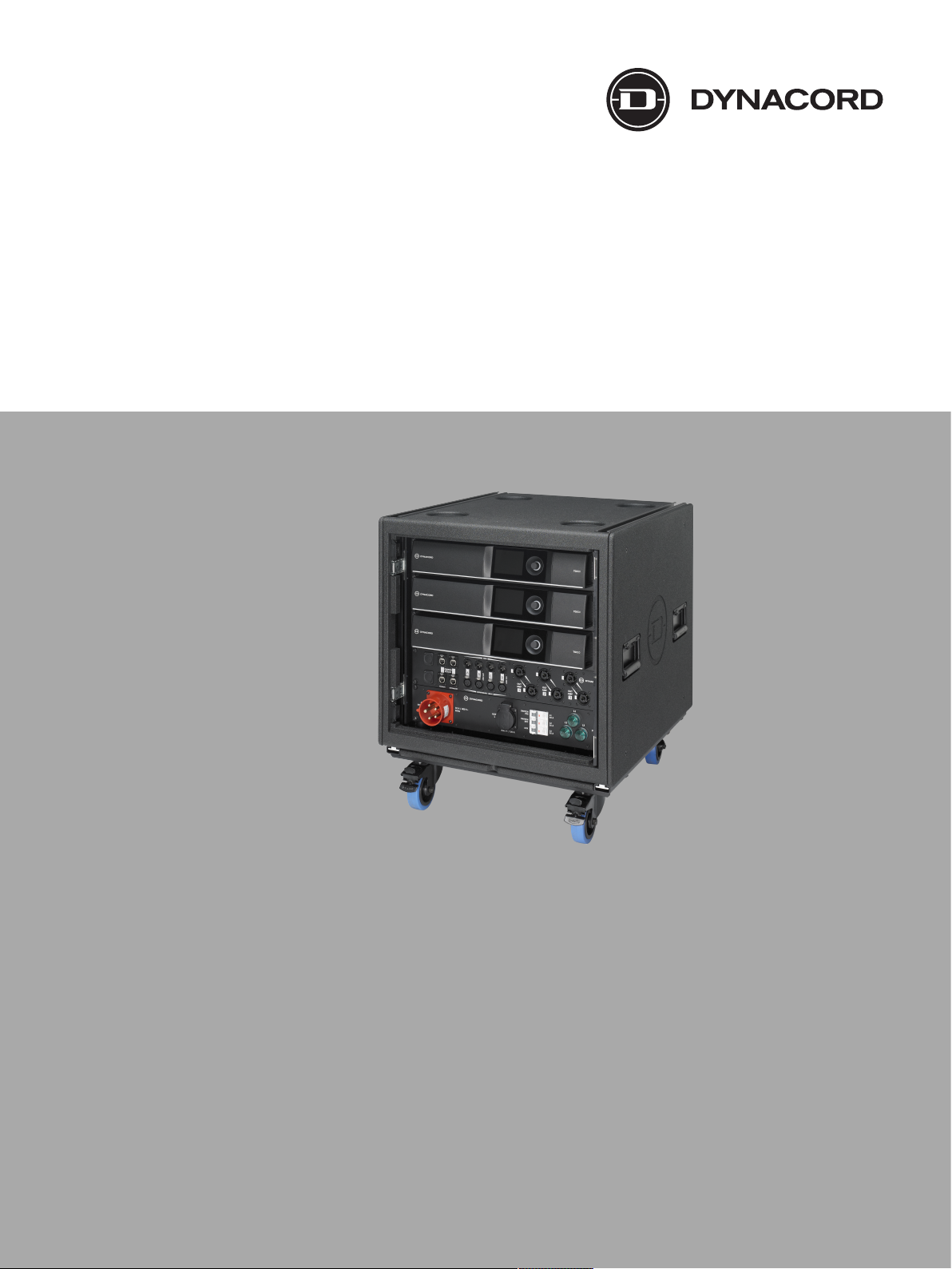
3 System overview
3.1 Application and intended use
The TGX amplifier system racks (SRTGX) are designed to power pro sound loudspeaker
systems in mobile applications such as concerts and corporate or cultural events. They are not
designed for use in residential areas. SRTGX contain three TGX20 power amplifiers, a power
distribution panel (PD32-EU or PD30-US), a connector panel for audio and OMNEO network
(CP34) and two managed Ethernet switches mounted on a 19-inch tray, completely pre-wired.
3.2 Scope of supply
Before starting to use the TGX system racks, please verify the shipment for completeness and
proper condition of each item.
Quantity Component
1 System rack TGX fully equipped
2 Connector rails (to attach the dolly board)
1 Dolly board
1 Safety Instructions manual
1 TGX Amplifier System Rack manual
1 PD32/PD30 Mains Power Distributor manual
1 TGX 4-Channel Power Amplifier manual
1 Network switch quick start guide
There are two versions of the system rack for use with either 230 V or 208 V 3-phase mains
power.
SR20TGX-EU SR20TGX-US
SR10F, system rack 1 1
TGX20 amplifier 3 3
PD32-EU power distro 1 -
PD30-US power distro - 1
CP34-connector panel 1 1
Network switch 2 2
2U blank panel 1 1
Bosch Security Systems, Inc. Installation manual 2019-03 | 02 | F.01U.346.534
Page 10

10 en | System overview TGX Amplifier System Rack
1
5
2
3
4
3.3 Front view
Figure3.1: TGX system rack front view
1. System rack, SR10F
2. TGX20 amplifiers
3. CP34 connector panel
4. CP32-EU (shown) or CP30-US
5. Dolly board with connector rails
6. 2U blank panel (not shown on the rear)
7. 2U tray with two network switches (not shown on the rear)
2019-03 | 02 | F.01U.346.534 Installation manual Bosch Security Systems, Inc.
Page 11

TGX Amplifier System Rack Handling, cooling, and placement | en 11
!
!
!
4 Handling, cooling, and placement
4.1 Handling
Caution!
Before transportation or use of the SRTGX rack make sure that the equipment is in good
condition. Examine the rack for damage to the wheels, connector bars, connector rails, and
doors.
Damage to the rack can cause accidents that lead to injuries and equipment damage.
Caution!
Do not move the system rack if the doors are not closed or have not been fully moved back
into the latching stop.
Partially recessed doors might cause damage to the other equipment or lead to injuries and
finally a damage of the door and/or its sliders.
Opening the system rack door
The amplifier system rack is equipped with two sliding doors.
To open the system rack door, do the following:
1. Using the cutout, pull the door open.
2. Open the door to a right angle.
3. Push the door back until it reaches its latching stop.
The latching prevents the door from siding outside.
Figure4.1: Opening the front door and sliding it back
Stacking the system racks
The amplifier system rack is designed for stacking. The system racks are connected by rigging
bars, which fit in the rigging rails on each side of the rack. The rigging bars are also used to
connect the dolly board to the system rack. This modular system allows to stack two or three
system racks in the footprint of just one.
Caution!
Do not use more than two racks on the dolly board. Moving two stacked racks on the dolly
board requires two people. A stack of three loaded racks is only safe to use straight on an
even ground. A stack of three empty racks is not permissible.
The center of gravity is high compared to footprint, so the stack can easily tip over and create
serious damage to equipment and injuries to personnel.
Bosch Security Systems, Inc. Installation manual 2019-03 | 02 | F.01U.346.534
Page 12

12 en | Handling, cooling, and placement TGX Amplifier System Rack
!
!
!
!
Caution!
A stack of three loaded racks is only safe to use straight on an even ground. A stack of three
empty racks is not permitted.
The center of gravity is high compared to footprint, so the stack can easily tip over and create
serious damage to equipment and injuries to personnel.
Figure4.2: System rack stack of two or three. Do not use more than two racks on the dolly board.
Caution!
The wheels of the dolly board are designed for solid, even surfaces. Donot push the rack on
lose ground, for example grass, sand, or gravel.
Uneven surfaces may cause the rack to tip over and create serious damage to equipment and
injuries to personnel.
Caution!
Always ensure that the rack bars are fully fitted and the safety pins are latched.
Non-latched safety pins and moving rack rails can cause damage to equipment and lead to
injuries.
Caution!
Two or more person lift and placement is recommended for stacking system racks.
Never attempt to move a loaded rack alone. Single person lift and placement of the loaded
system rack could cause injury.
To stack the system racks, do the following:
1. Remove the rigging bars that attach the dolly board to the rack by lifting the safety pins
and moving them out.
2. Carefully place a rack on top of the first rack.
3. Insert the rigging bars in the rigging rails.
Keep the side with the safety hole on the rear of the rack.
4. Push the rigging bars all the way in.
5. Latch the safety pins on the system rack rails into the holes of the rigging bars.
Make sure the safety pins are latched securely to the rigging bars.
Figure4.3: Connector bar with locking hole to latch the safety pins (left) Dolly with rigging rails (right)
2019-03 | 02 | F.01U.346.534 Installation manual Bosch Security Systems, Inc.
Page 13

TGX Amplifier System Rack Handling, cooling, and placement | en 13
0.6 m
(2 ft)
0.6 m
(2 ft)
4.2 Cooling and placement
When placing the TGX amplifier system racks make sure to provide a minimum space of 0.6 m
(2 ft.) to the front and rear of the rack to allow sufficient airflow. In operation both doors have
to be fully opened.
Figure4.4: Allow a minimum of 0.6 m (2 ft.) space for sufficient airflow
Bosch Security Systems, Inc. Installation manual 2019-03 | 02 | F.01U.346.534
Page 14

14 en | Power distribution panel TGX Amplifier System Rack
5 Power distribution panel
The TGX amplifier system racks have a power distribution panel that allows to drive the TGX
amplifiers as well as the integrated network switches from one 3-phase mains connection.
There are two versions available.
5.1 PD32-EU power distribution panel
The PD32-EU is designed for a mains supply network configuration of: 3-phase, 230/400V~
-50/60Hz - 32Amax. It has a 32A CEE (CEKON) male connector that accepts the corresponding
CEE female connector.
5.2 PD30-US power distribution panel
The PD30-US is designed for a mains supply network configuration of: 30A 3øY 120/208V~ VAC
~ 60Hz. It has a NEMA 30A 3øY 120/208V VAC male connector that accepts the corresponding
NEMA female connector.
For more information, refer to the PD32/PD30 Mains Power Distributer manual.
2019-03 | 02 | F.01U.346.534 Installation manual Bosch Security Systems, Inc.
Page 15

TGX Amplifier System Rack Connector panel CP34 | en 15
6 Connector panel CP34
The TGX system racks features the CP34 connector panel, designed for three 4-channel
amplifiers with OMNEO networking. All connections for the OMENO network (incl. Dante
audio and OCA), additional analogue and AES-3 inputs and the outputs to the speakers are
available. The three TGX amplifiers are connected via the network switches for glitch free
redundancy.
Figure6.1: CP34 connector panel, front view
1. Blank cover for customer options (e.g. optical network connectors)
2. Primary OMNEO/Dante network connection on etherCon RJ45
3. Secondary OMENO/Dante network connection on etherCon RJ45
4. XLR audio connections (inputs and through) for analogue line level and AES-3
5. NL8 speaker connectors (2 in parallel) Pins 1 - 4 for channels A - D
6.1 Internal wiring
The SRTGX system racks are pre-wired and pre-configured for use via the connector panel.
Figure6.2: Audio wiring scheme: analogue/AES3 inputs and amplifier outputs
Bosch Security Systems, Inc. Installation manual 2019-03 | 02 | F.01U.346.534
Page 16

16 en | Connector panel CP34 TGX Amplifier System Rack
Input signals (analogue or AES3) from the CP34 connector panel are connected to the top
amplifier and linked through. The audio outputs from the bottom amplifier are connected to
the THROUGH sockets on the CP34.
Figure6.3: Switch tray and network wiring scheme: OMNEO (Dante audio + OCA control)
The SRTGX racks feature a fully redundant network connection. The two Ethernet switches are
configured identically as primary and secondary distribution, the cabling to the amplifiers is
accordingly. The two SFP ports are not utilized in the factory default configuration. They can
be used in conjunction with the blank sockets on the CP34 for individual, customer specific
retrofits with optical network connectors.
2019-03 | 02 | F.01U.346.534 Installation manual Bosch Security Systems, Inc.
Page 17

TGX Amplifier System Rack Connector panel CP34 | en 17
Figure6.4: Power cabling, top to bottom phase L1, L2, L3, respect. X, Y, Z
The amplifiers are connected to the power outlets of the PD32-EU / PD30-US for an optimized
power input of the amplifiers.
For more information, refer to the PD32/PD30 Mains Power Distributer manual.
6.2 System wiring
The SRTGX racks are designed for an easy set-up of larger systems that contain multiple
system racks by daisy-chaining audio signal and remote control data.
Figure6.5: Daisy-chain of multiple system racks in a larger system
An advantage of the OMNEO network protocol is the combination of Dante audio and OCA
remote control data in once network cable. Using the primary and secondary line the system
has full redundancy for audio (glitch-free) as well as remote control and supervision with
simply daisy-chaining two network cables between the system racks. It is highly recommended
to always use that built-in redundancy and run redundant cabling for a reliable performance.
Bosch Security Systems, Inc. Installation manual 2019-03 | 02 | F.01U.346.534
Page 18

18 en | Connector panel CP34 TGX Amplifier System Rack
Figure6.6: OMNEO / Dante / OCA connection of multiple system racks with primary and secondary line
If no Dante audio signal is used, or as an additional (third level) back-up, digital audio signal in
AES3 format can also be connected throughout multiple racks by daisy-chaining.
Figure6.7: AES3 digital audio signal connection of multiple racks
In addition to the OMNEO cabling audio signal can be fed as digital signal in AES3 format as
well as analogue line level. Note the AES3 format is using 2 signals on one connector, which is
B for amplifier channels A & B and D for amplifier channels C & D.
The same schematic applies to analogue line level signals, just with one signal per connector.
Notice!
For reliable performance it is important to use only high-quality cabling throughout the entire
system. System performance is depending on the entire cabling to work within specifications.
System performance is depending on the entire cabling to work within specifications. For
network cabling shielded cables with at least CAT5e specification must be used, we
recommend to use shielded CAT6 cabling.
2019-03 | 02 | F.01U.346.534 Installation manual Bosch Security Systems, Inc.
Page 19

TGX Amplifier System Rack Connector panel CP34 | en 19
6.3 Using blank panel for customized connectors on the front
Use the blank panel on the front for customer specific connectors (e.g. loudspeaker
multicores) with SRTGX rack, it is possible to re-arrange the power distribution (PD30 / PD32)
with the switch tray that is covered by a 2U 19-inch blank panel.
Figure6.8: SRTGX with switch-tray on the front and power distribution on the rear
Bosch Security Systems, Inc. Installation manual 2019-03 | 02 | F.01U.346.534
Page 20

20 en | Maintenance and inspection TGX Amplifier System Rack
7 Maintenance and inspection
Cleaning of the rack, its doors, attachments and mounted equipment shall only be done using
a dry cloth. The outer wooden rack shell can also be cleaned using a light brush. Check
regularly (best before and after use) that the wheels on the dolly boards are rotating easily.
Blocking and even partially blocking wheels shall be replaced. Check regularly (best before
and after use) that all rigging rails and safety pins are available and fully functional. Damaged
or missing parts have to be replaced immediately.
The overview for global service and spare parts is available on www.dynacord.com
2019-03 | 02 | F.01U.346.534 Installation manual Bosch Security Systems, Inc.
Page 21

TGX Amplifier System Rack Technical data | en 21
8 Technical data
8.1 System rack SR20TGX
Amplifier channels 12
Audio Connections
Balanced line level input / AES3 4 / 2 XLR f (Neutrik)
Balanced line level out / AES3 4 / 2 XLR m (Neutrik)
Amplifier outputs 3 x 2 NL8 (Neutrik speakON)
Ethernet Connections 2 x 2 RJ45 (Neutrik etherCON)
Primary and secondary
Network switches Managed GB switches, Layer-3, 10-port, pre-configured
for OMENO/Dante
Mains Power Inlet -EU CEE 32A-3phase-230/400V
Main Power Inlet -US NEMA L21-30, 208 VAC
Ambient Temperature Limits +5°C to +40°C (40°F to 105°F)
Color Black
Dimensions (W x H x D) w/o dolly board in mm 600 x 558 x 655
Dimensions (W x H x D) with dolly board in mm 600 x 718 x 655
Weights with/without dolly board
SRTGX20-EU 123,7 kg (272.7 lb)/112,7 kg (248.5 lb)
SRTGX20-US 123,8 kg (272.9 lb)/112,8 kg (248.7 lb)
System rack empty with/without dolly board 53,0 kg (116.9 lb)/42,0 kg (92.6 lb)
Payload (max. weight allowed to be loaded) 70,7 kg (155.9 lb)
Shipping weight 158 kg (350 lb)
8.2 Power distribution panel PD30/PD32
Power distribution panel PD30-US PD32-EU
Mains power inlet NEMA L21-30, 208 VAC CEE 32A-3phase-230/400 V
Mains power outputs 3 x 30 A, 208 V~ 3 x 32 A, 230 V~
Mains power outlet 3x Neutrik NAC3FC-HC
Aux power outputs 3 x 15 A, 120 V~ 3 x 16 A, 230 V~
Ambient temperature limits +5°C to +40°C (40°F to 105°F)
Color Black
Dimensions (W x H x D) in mm 482 x 88 x 160
Weight 5.7 kg (12.6 lb) 5.8 kg (12.8 lb)
Bosch Security Systems, Inc. Installation manual 2019-03 | 02 | F.01U.346.534
Page 22

22 en | Technical data TGX Amplifier System Rack
8.3 Connector panel CP34
Audio inputs 4 XLR f ( line level, 2 for AES-3)
Audio outputs (through) 4 XLR m (line level, 2 for AES-3)
Network connection 2 x 2 RJ45 (Neutrik etherCON)
Blank for customer options 2
Amplifier outputs 3 x 2 SpeakON NL8
Dimensions 483 x 88 x 160
Weight 5,6 kg (12.4 lb)
For more information, refer to the PD32/PD30 Mains Power Distributer manual.
2019-03 | 02 | F.01U.346.534 Installation manual Bosch Security Systems, Inc.
Page 23

TGX Amplifier System Rack Technical data | en 23
8.4 CP 34 block diagram
Bosch Security Systems, Inc. Installation manual 2019-03 | 02 | F.01U.346.534
Page 24

24 en | Technical data TGX Amplifier System Rack
8.5 Dimensions
Figure8.1: Dimensions: SR20TGX amplifier system rack
2019-03 | 02 | F.01U.346.534 Installation manual Bosch Security Systems, Inc.
Page 25

Page 26

Page 27

Page 28

Bosch Security Systems, Inc.
130 Perinton Parkway
Fairport, NY 14450
USA
www.dynacord.com
© Bosch Security Systems, Inc., 2019
 Loading...