

Page 1
Engineering Data Sheet
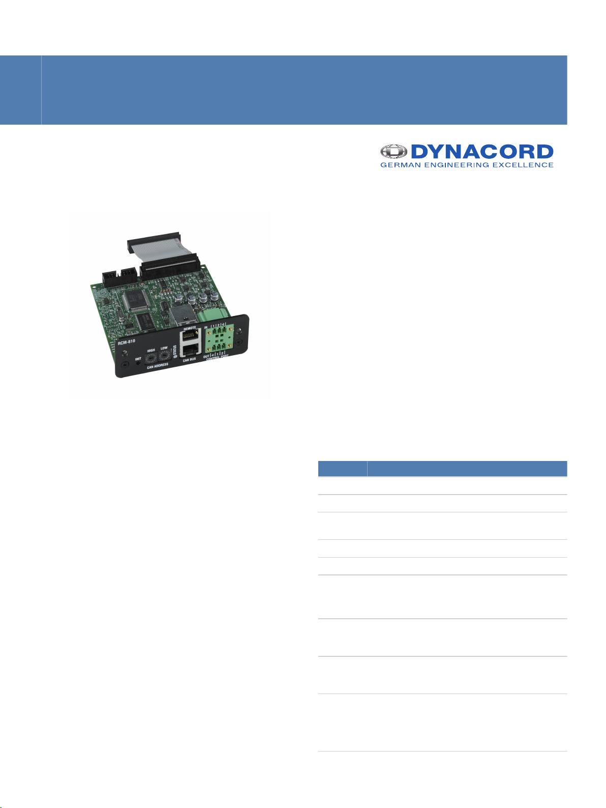
RCM-810
▪ Enable powerful control and supervision capabilities
▪ Integrate up to 100 devices in each remote control
network, 250 with multiple networks
▪ Freely programmable control inputs and outputs
The RCM-810 Remote Control Module is an optional
module for supervision and remote control of power
amplifiers.
RCM-810 modules allow the amplifiers to be
integrated into a remote control network with up to
100 devices. Up to 250 amplifiers can be used in an
IRIS-Net project when multiple networks are used.
Apart from the network port, the RCM-810 also offers
freely programmable control inputs and control
outputs.
Additional RCM-810 features:
• Control/Configuration:
• Power ON/OFF
• Power On Delay
• Mute
• Control Inputs/Outputs
Supervision/Status indicators:
• Load supervision for each amplifier channel
• Output VU
• Protect
• Limit
• Pilot tone
• Temperature
• Gain/Sensitivity
• Control Inputs/Outputs
For further details please check the owner’s manual of
the amplifier which the RCM-810 will be used in.
▪ Load-monitoring for each channel
▪ EN 54-16: 2008
Parts included
Quantity Components
1 RCM-810
1 Ribbon cable (34-pole, 60 mm)
1 Euroblock connector 6-pole (Phoenix, MC 1,5/6-
STF-3,81, 1827745, F.01U.104.179)
4 Screw M3x10, combination TORX
1 Data sheet
TORX is a registered trademarks of Acument Intellectual Properties, LLC.
Technical specifications
Remote control and software IRIS-Net, Multiple PCs possible,
MS Windows 2000, XP, Vista, 7,
8
Maximum configuration 250 Amplifiers in total, 100
Amplifiers per CAN bus, 1000
meter cable run
Amplifier supervision Operation mode, temperature,
output voltage and current,
impedance of connected
speakers, protection mode
status, pilot tone detection
Page 2
Controller
SRAM
Latch
CAN
CAN-LED
FRAM
/ATMEL_PROG
/RCM_EN
RCM_CLK
RCM_MOSI
RCM_MISO
/RCM_DETECT
REMOTE
CAN BUS
G
a
l
v
a
n
i
c
I
s
o
l
a
t
i
o
n
P/S
DC
DC
CAN
ADDRESS
+5V
CAN-LED
0
2
1
3
4
5
6
7
8
9
A
B
C
D
E
F
0
2
1
3
4
5
6
7
8
9
A
B
C
D
E
F
CONTROL
PORT
+5V
DGND
+5V
Reset
Watchdog
+5V
Test
AMP ID
POWER ON
MUTE A / B
STANDBY
LIMIT /
PROTECT /
REDUCTION
CURRENT A- / B-
CURRENT A+ / B+
VOLTAGE A- / B-
VOLTAGE A+ / B+
AGND
+15V
-15V
U-TEMP
ADC
Only 2 Channel AMP
IrisNet LED
+15V
AGND
-15V
TEMP_Board
BRIDGED
POWER_GOOD
Pilot Tone
Detection
INIT
| RCM-810
2
Network supervision CAN bus failures, defective or
missing amplifiers, bandwidth,
failure protocol and messaging
CAN interface 10–500 kbaud, 2 x RJ-45 (IRIS-
Net Control)
GPIO control port 2 x 3-pole Euro block
• 2 Control Inputs
• 2 Control Outputs (max.
18 V / 250 mA per output)
• 2 Reference Outputs (+5
V, 200 mA / GND)
Supply voltage/current +5 V DC / 320 mA
+15 V DC / 80 mA
-15 V DC / 80 mA
Power consumption 4 W
Electromagnetical environment E1, E2, E3
Operating temperature 0 °C to 40 °C
Product dimensions (Width x
103.5 x 37 x 103 mm
Height x Depth)
Net weight 115 g
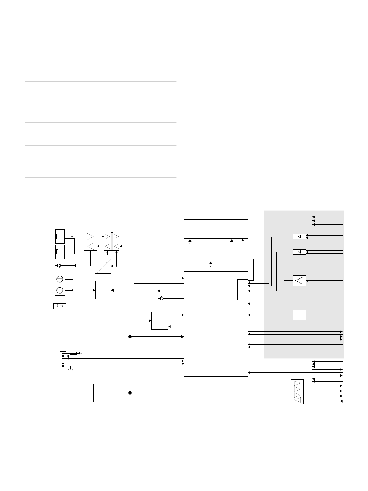
Circuit diagram
Page 3

3 | RCM-810
Dimensions
Installation/configuration notes
Installation (dual-channel amplifier)
Danger!
These installation instructions are for use by
qualified service personnel only. To reduce the
risk of electric shock do not perform any serv-
icing other than that contained in the owner’s
manual unless you are qualified to do so.
1. Switch off the power to the amplifier and remove the
mains lead.
2. Remove the 4 screws (1) from the top cover of the
amplifier.
3. Loosen the top cover as shown (2) and remove it by
pulling it out towards the front panel
4. Remove the cover panel from the rear panel (2
screws)
5. Lay the black cable as shown in following illustration.
Page 4

1
2
4 | RCM-810
6. Slide the RCM-810 module into the slot and secure it
in place using the 2 screws
7. Gently push the 60 mm ribbon cable into the
connector labelled CN4 on the RCM-810 and the
connector labelled CN3 on the amplifier main board
(see illustration below)
2. Remove the 8 screws (1) from the bottom cover of
the amplifier
3. Loosen the bottom cover as shown (2) and remove it
by pulling it out towards the front panel
4. Remove the cover panel from the rear panel (2
screws)
5. Release the 16-pole ribbon cable by cutting the tie
wrap (3)
8. Refit the top cover
9. Set the module’s CAN address using the ADDRESS
selector switches
10. Connect the interfaces required (CAN, Control Port)
11. Reconnect the mains lead and switch the amplifier
on, the RCM-810 is automatically detected and is now
ready for use
Installation (multi-channel amplifier)
Danger!
These installation instructions are for use by
qualified service personnel only. To reduce the
risk of electric shock do not perform any serv-
icing other than that contained in the owner’s
manual unless you are qualified to do so.
1. Switch off the power to the amplifier and disconnect
the mains lead
6. Insert the RCM-810 module into the slot
7. Plug the 16-pole ribbon cable into the connector
labelled CN3 on the RCM-810 module
8. Slide the module into place locating it into the guide
slot (4) on side of the chassis and secure it in place
using the 2 screws
9. Refit the bottom cover making sure the ribbon cable
will not be damaged
10. Set the module’s CAN address using the ADDRESS
selector switches
11. Connect the interfaces required (CAN, Control Port)
12. Reconnect the mains lead and switch the amplifier
on, the RCM-810 is automatically detected and is now
ready for use
Ordering information
RCM-810
RCM-810 Remote Control Module for IRIS-Net
Order number F.01U.101.277
Page 5

5 | RCM-810
Bosch Sicherheitssysteme GmbH
Robert-Bosch-Ring 5
85630 Grasbrunn
Germany
www.dynacord.com
© Bosch Sicherheitssysteme GmbH, 2014 | Data subject to change without notice
Document Number | Vs1 | 15. Jan 2014
 Loading...