

DynaColor DynaGuard 090 series User Manual

Version 1.2
00P3DG090DSEA2
DynaGuardTM 090 Series DVR
User’s Manual
00P3DG090DSEA2

User’s Manual
2
User’s Manual
3
Caution and Preventive Tips
• Take care not to drop the unit or subject the unit to major shocks or jolts.
• Do not place this unit on an unstable stand, bracket or mount.
• This unit is designed for indoor use only. Do not place the unit near water or in other
extremely humid conditions.
• This unit should not be placed in a built-in installation unless proper ventilation is provided.
• Please check the used type of power source before you plug and operate the unit;
AC100V ~AC240V is acceptable.
• If the clearing is necessary, note to plug the unit from the outlet before uncovering the top
cover. Do not use liquid cleaners or aerosol cleaners. Use only a damp cloth for cleaning.
• Always power down the system prior to connecting and disconnecting accessories, with
the exception of USB devices.
• Lithium battery: Danger of explosion if battery is incorrectly replaced. Replace with the
same or equivalent type recommended by the battery manufacturer. Dispose of used
batteries according to the battery manufacturer’s instructions.
• Do not block the fan on the bottom of the unit for air ventilation.
This symbol intends to alert the user to the presence of important operating and
maintenance (servicing) instructions in the literature accompanying the
appliance.
This symbol intends to alert the user to the presence of unprotected “Dangerous
Voltage” within the product’s enclosure that may be strong enough to cause a
risk of electric shock.

User’s Manual
4
Important Information
Before proceeding, please read and observe all instructions and warnings in this manual.
Retain this manual with the original bill of sale for future reference and, if necessary, warranty
service. When unpacking your unit, check for missing or damaged items. If any item is missing,
or if damage is evident, DO NOT INSTALL OR OPERATE THIS PRODUCT. Contact your
dealer for assistance.
Rack Mounting
Consult with the supplier or manufacturer of your equipment rack for the proper hardware and
procedure of mounting this product in a safe fashion. Avoid uneven loading or mechanical
instability when rack-mounting units. Make sure that units are installed to get enough airflow for
safe operation. The maximum temperature for rack-mounted units is 40 °C. Check product
label for power supply requirements to assure that no overloading of supply circuits or over
current protection occurs. Mains grounding must be reliable and uncompromised by any
connections.

User’s Manual
5
Table of Content
1. Overview .......................................................................................................................7
1.1 Product Key Features ..........................................................................................8
1.2 Product Application Diagram................................................................................9
2. System Setup................................................................................................................9
2.1 Position the Unit...................................................................................................9
2.2 Selecting Video Format......................................................................................10
2.3 Connecting Devices to the Unit..........................................................................10
2.4 Rear Panel Connections .................................................................................... 11
3. General System Setup ...............................................................................................14
3.1 Front Panel Introduction ....................................................................................15
3.1.1 LED Definition ......................................................................................15
3.1.2 Function Keys.......................................................................................16
3.2 Power Up / Down the Unit .................................................................................18
3.3 Entering OSD Setup Menu ................................................................................19
3.4 System Date / Time Setting ...............................................................................20
3.4.1 Set Date / Time.....................................................................................20
3.4.2 Daylight Saving Time............................................................................21
3.5 Record Schedule / Quality Setting .....................................................................22
3.5.1 Record Mode........................................................................................22
3.5.2 Schedule Setup ....................................................................................23
3.5.3 Preset Record Configuration ................................................................23
3.5.4 To Record Event Video Only ................................................................24
4. Basic Operation..........................................................................................................24
4.1 Viewing Live / Playback Video ...........................................................................24
4.1.1 Viewing Modes .....................................................................................24
4.1.2 Digital Zoom .........................................................................................25
4.1.3 Viewing Live Cameras..........................................................................25
To Freeze Live Image..............................................................................25
4.1.4 Viewing Recorded Video ......................................................................25
Key Usage in Playback ...........................................................................26
Pause Playback and Single Step Forward..............................................26
4.2 Sequence Setup ................................................................................................27
4.3 Searching Recorded Video ................................................................................27
4.3.1 Searching by Time................................................................................27
4.3.2 Searching by Event ..............................................................................28
4.4 Video Export ......................................................................................................29
4.4.1 ezBurn Introduction ..............................................................................29

User’s Manual
6
4.4.2 To Export Normal Video........................................................................30
4.4.3 To Export Event Video ..........................................................................31
4.5 Deleting Recorded Video ...................................................................................31
4.6 Dome Control.....................................................................................................32
4.6.1 Dome Connection.................................................................................32
4.6.2 Dome Protocol Setup ...........................................................................33
4.6.3 RS485 Setup ........................................................................................33
4.6.4 Dome Controlling Keys.........................................................................34
4.6.5 Setting Preset Points............................................................................36
4.6.6 Calling Preset Points ............................................................................37
Appendix A: Technical Specifications ...........................................................................38
Appendix B: Record Duration.........................................................................................40
User’s Manual
7
1. Overview
The DynaGuardTM 090 Series DVR is an integrated digital video recorder that
combines the features of a time-lapse audio / video recorder, a multiplexer,
and a video server to create a single security CCTV solution.
Its outstanding triplex operation enables users to view live or playback
recorded video, and remote access through network simultaneously, while
recording other video, and to view wanted recorded video instantly by
entering the time and date or selecting recorded video from the event list.
DynaGuardTM 090 Series DVR includes DynaRemote Lite, the remote
viewing software that is a Web-browser plug-in, allows user to view live or
recorded video images. The remote software is stored in DynaGuardTM 090
Series DVR and deployed over a LAN, WAN or Internet connection to remote
Windows-based computers. This simplifies the installation and maintenance
of the software components so all remote users are kept up to date.
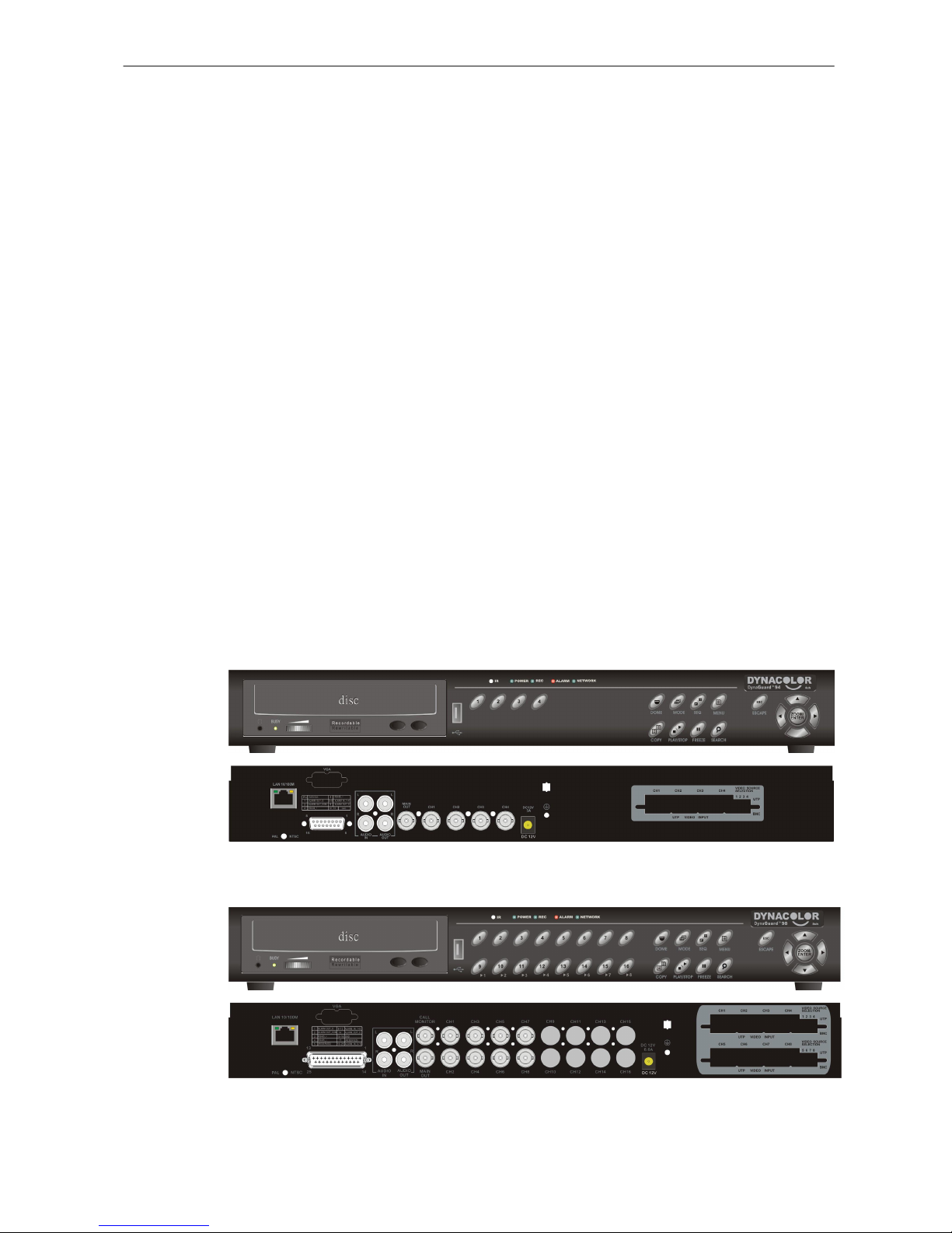
Below lists the front/ rear panels of DynaGuardTM 090 Series DVR family, the
number of channels is the only difference among the three models.
DynaGuardTM 090 – 4ch
DynaGuardTM 090 – 8ch
User’s Manual
8
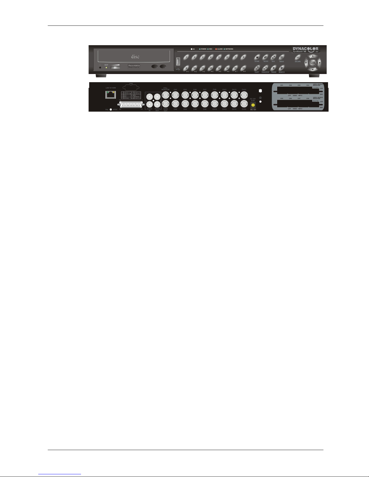
DynaGuardTM 090 – 16ch
1.1 Product Key Features
The DynaGuardTM 090 Series DVR offers advanced features not typically
found in standard multiplexers; it integrates the full features of a DVR,
multiplexer and video server (by using the software DynaRemote Lite). The
key features of DynaGuardTM 090 Series DVR are listed as follows.
• MPEG-4 high quality compression, 5~10 times smaller than MJPEG
• Triplex operation (recording, playback and network access)
• Remote monitoring, instant recording and dome camera control via
Ethernet
• Support VGA main output (optional)
• Live display: 120pps (NTSC)/ 100pps (PAL)
• 1 Channels, in & out, for audio recording
• Support up to 2 internal HDDs
• USB2.0 port for video clip exporting, support USB ThumbDrive
®
• Easy software upgrade via USB ThumbDrive®
• Export DVR file which can be played via DynaPlayer
• DynaPlayer application software will be attached with exported disks
• Multiple built-in dome camera protocol: DynaColor, Pelco D, Pelco P,
AD422 and Fastrax 2.
• Digital Zoom 2X2, available in live mode
• Pre-Alarm recording
• IR Remote controller (Optional)
• Multiple language on-screen menus
• Network software supports static IP and DHCP
• Support RS-485 remote control keyboard (Optional)
User’s Manual
9
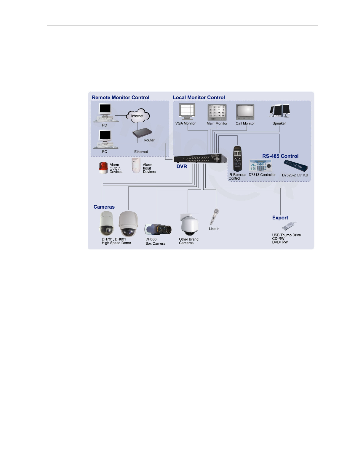
1.2 Product Application Diagram
Connect the unit with other devices as shown in the system diagram to
complete a video surveillance solution. The figure shows also the
expandability and flexibility of this digital recording system.
2. System Setup
The notices and introduction on system installation will be described
particularly in this chapter. Please follow the description to operate the unit.
In order to prevent the unit from data loss and system damage that caused by
a sudden power fluctuation, use of an Uninterruptible Power Supply (UPS) is
highly recommended
2.1 Position the Unit
Position / mount the DynaGuardTM 090 Series DVR in a proper place and be
sure to power off the unit before making any connections. The placed location
should avoid hindering or blocking the unit from airflow. Enough airflow is
needed to protect the unit from overheating. The maximum allowable
temperature of operating environment is 40°C.

User’s Manual
10
The unit utilizes heat-conducting techniques to transfer internal heat to the
case, especially to the bottom side of the unit.
NOTE: Be sure not to remove the rubber feet, and always leave
a space for air ventilation on the unit’s bottom side.
2.2 Selecting Video Format
The DynaGuardTM 090 Series DVR is designed to operate under either NTSC
or PAL video formats. The switch is positioned on the rear panel.
2.3 Connecting Devices to the Unit
This section lists some important notices that should be read before
making any connections to the DynaGuardTM 090 Series DVR.
NOTE: Connect short-term devices, such as USB ThumbDrive®,
USB CD-ROM, USB Hard Disk Drive, etc., only after the unit is
successfully powered up.
Connecting Required Devices
Before power up the unit, you should connect cameras and a main monitor to
the unit for basic operation. If needed, connect a call monitor for displaying
full screen video of all installed cameras in sequence.
Connecting Short-term Device
If you plan to install any short-term devices to the DynaGuardTM 090 Series
DVR and use them as part of the unit system, such as USB CD-ROM, USB
Hard Disk Drive, etc, make sure those devices are connected only after
the unit is powered up. Because DynaGuardTM 090 Series DVR can
recognize the external devices only after the power-up process is done
completely.
User’s Manual
11
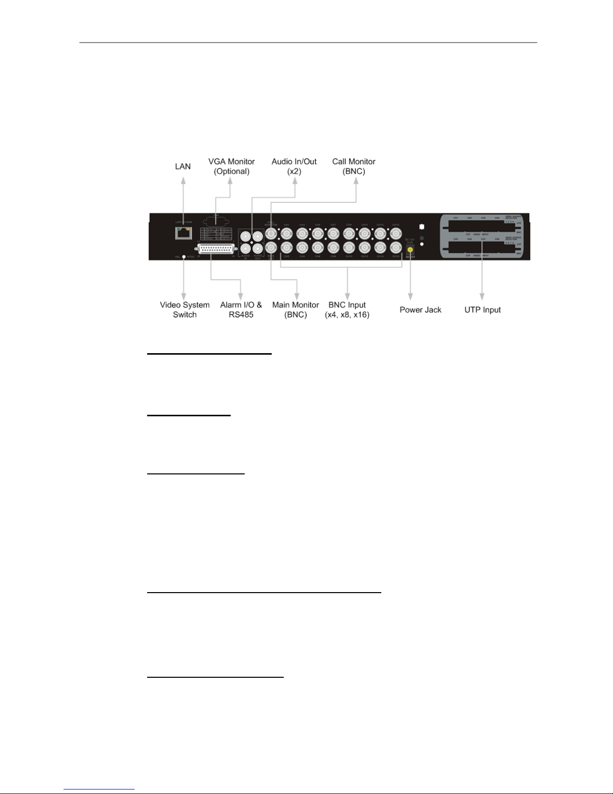
2.4 Rear Panel Connections
There are various connectors on the rear panel used for DynaGuardTM 090
Series DVR installations. The following figure shows the connectors by name;
and followed by the detailed description of each connector.
LAN Connector (RJ-45)
The DynaGuardTM 090 Series DVR is capable of networking. The LAN port
opens the door of DynaGuardTM 090 Series DVR to Ethernet.
USB Connector
There is a USB 2.0 port on the rear panel for users to connect external USB
devices to the unit, such as ThumbDrive® or CD-ROM.
Audio In / Out (x2)
The DynaGuardTM 090 Series DVR provides two sets of audio recording.
Audio In RCA connector is offered for connecting an audio source device (e.g.
external amplified microphone) to the unit; Audio Out RCA connector is
offered for connecting an audio output device (e.g. amplified speakers) to the
unit.
Call Monitor (for 8ch and 16ch Models only)
The call monitor is used to display full screen video of all installed cameras in
sequence. The BNC call monitor connector allows user to connect the
DynaGuard
TM
090 series unit with an optional call monitor.
Main Monitor (BNC/ VGA)
BNC and VGA output connectors are offered for connecting to a main monitor.
The main monitor displays live image and playback recorded video in either
full-screen or split-window format. VGA output connector is optional.
User’s Manual
12
Visdeo System Switch
It is used for adjusting the video system of the unit.
Video Input
A group of BNC connectors are available for video input streams from
installed cameras.
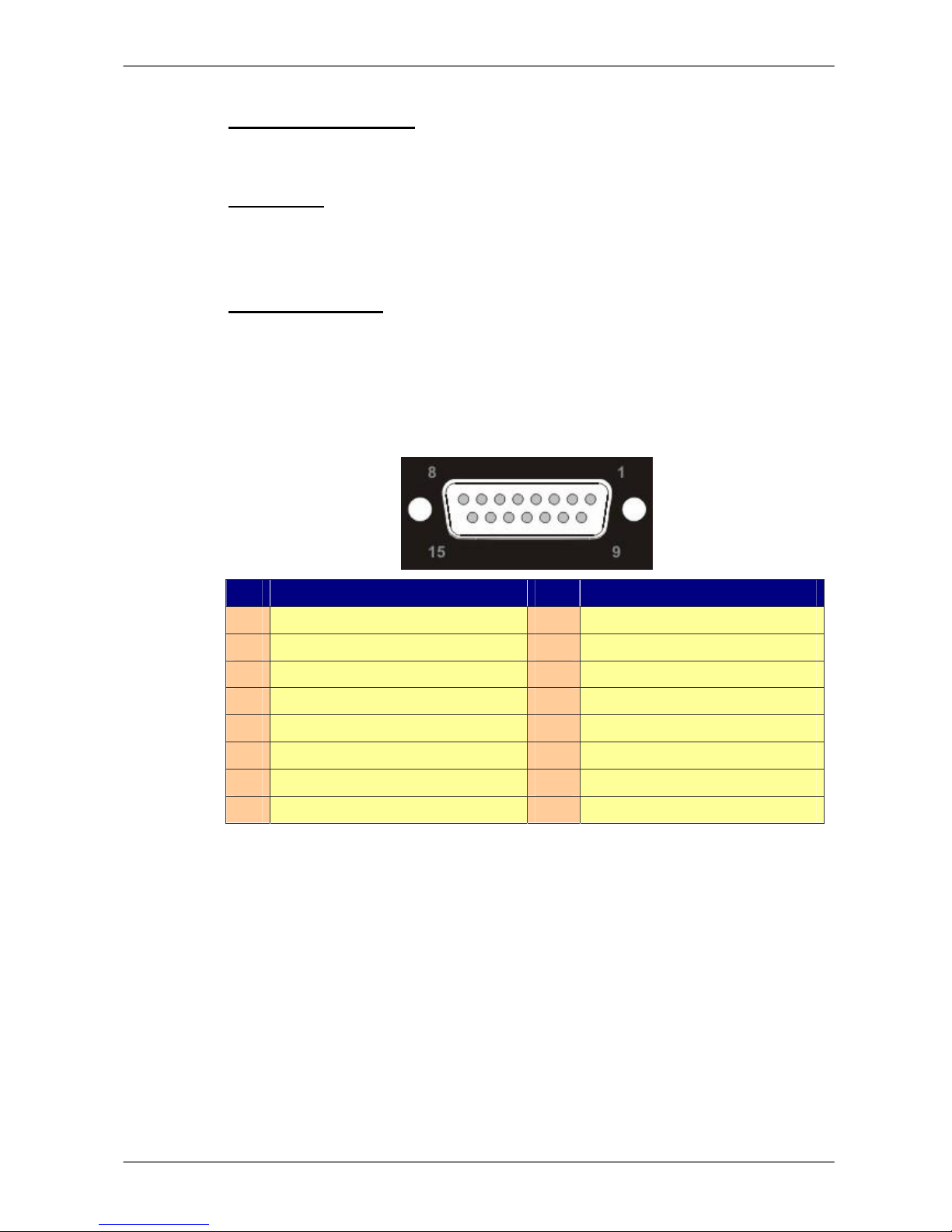
Alarm I/O & RS485
The unit provides an alarm I/O and RS485 port that offers user the flexibility
required to connect the unit to the other device. The pin definition for each
model is listed as below tables:
Pin Definition for 4ch-Model:
Pin Definition Pin Definition
1
ALARM OUT O
9
Alarm Out C
2
ALARM OUT COM
10
GND
3
RS485 D/R+
11
-
4
RS485 D/R-
12
-
5
ALARM In 1
13
-
6
ALARM In 2
14
-
7
ALARM In 3
15
-
8
ALARM In 4
User’s Manual
13
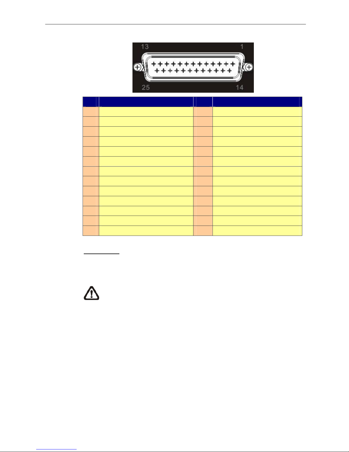
Pin Definition for 8ch/16ch Model:
Pin Definition Pin Definition
1
ALARM OUT O
14
Alarm OUT C
2
ALARM OUT COM
15
GND
3
RS485 D/R+
16
GND
4
RS485 D/R-
17
Reserved
5
Reserved
18
ALARM In 9 (for 16ch only)
6
ALARM In 1
19
ALARM In 10 (for 16ch only)
7
ALARM In 2
20
ALARM In 11 (for 16ch only)
8
ALARM In 3
21
ALARM In 12 (for 16ch only)
9
ALARM In 4
22
ALARM In 13 (for 16ch only)
10
ALARM In 5
23
ALARM In 14 (for 16ch only)
11
ALARM In 6
24
ALARM In 15 (for 16ch only)
12
ALARM In 7
25
ALARM In 16 (for 16ch only)
13
ALARM In 8
Power Jack
The DynaGuardTM 090 Series DVR has a free voltage DC power connection
jack. Please connect the power adapter that ships with the unit.
NOTE: Use of other power adapter may cause overloading.
 Loading...