

DynaColor DG80II Setup Manual
00P5DG080F1SEB1 1
Versatile H.264 DVR
Setup Guide
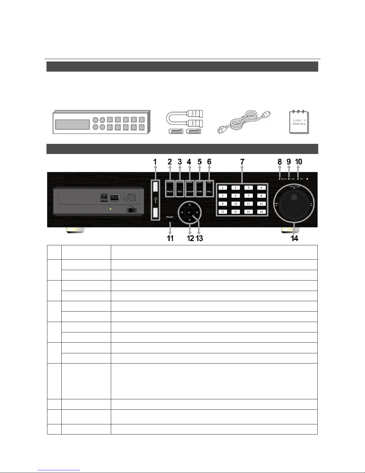
Package Content
Inspect the packaging carton. Make sure the Versatile H.264 DVR is properly delivered. Remove all
items from the box and make sure the box contains the following items.
Versatile H.264 DVR SATA Cable Power Cord User’s Manual
Front Panel
1 USB 2.0 Port
The USB 2.0 port allows users to connect an external USB device to the
unit, such as a USB ThumbDrive or a USB mouse.
2
PLAY/STOP
Press once to start the playback of recorded video. Press again to exit.
MODE
Press this key to view in full-screen or multiple window modes.
3
FREEZE
Press this key to freeze the current viewing screen.
SEQUENCE
Press this key to start automatic sequence display of cameras.
4
MENU
Press this key to enter the OSD setup menu.
SEARCH
Press this key to search recorded video by date/time or event.
5
COPY
This key is used for marking time in quick video export function.
DOME
Press this key to enter Dome Camera Control mode.
6
ESC
Press this key to cancel or exit from certain control mode.
CALL
Press this key to enter Call Monitor Control mode.
7 Channels
1. In Live and Playback modes, press any key to view the corresponding
video in full-screen.
2. In input interface, 1~10 can be used for direct input of numbers 0~9.
3. In Dome Camera Control mode, 1 is for entering the Set/ Go preset
menu; 11~16 is for quick access of preset points 1~6.
8 Alarm LED
It lights up when an alarm is triggered.
9 Network LED
It lights up when network is connected. In addition, it blinks when data is
being transmitted via the network.
10 Record LED
It blinks when videos are being recorded.
2
11 Power Key
Press and hold this key to trigger the quick shutdown function.
12 Direction Keys
1. In Zoom mode, these keys function as normal direction keys.
2. In the OSD setup menu, the direction keys are used to move the
cursor to previous or next fields. To change the value in the selected
field, press UP / DOWN keys.
13 ENTER
1. In OSD menu or selection interface, press these key to make the
selection or save settings.
2. In live full-screen viewing mode, press this key to view a 2× zoom
image; press it again to return.
14 Shuttle/ Jog
This is used to control playback operations.
Rear Panel
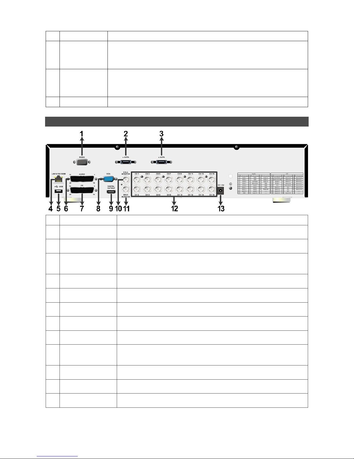
1
RS232
The RS232 communication port is for connection to a POS device.
2
e-SATA
(for Record)
Users can connect an e-SATA storage device via this port to expend
HDD capacity of the DVR.
3
e-SATA
(for Export)
Users can connect an e-SATA storage device via this port to export
recorded videos in the DVR.
4
LAN 10/100/1000M
(RJ-45)
The DVR is capable of networking. Once the unit is connected to the
LAN network, users can remotely access the DVR through the remote
software on a PC.
5
USB Port
This USB port allows users to connect a USB mouse with PS/2
protocol.
6
Audio
A D-Sub Audio connector is provided for the DVR to connect audio
source devices and Main/Call monitors audio ouput devices.
7
Alarm I/O
&
RS-485
The DVR provides alarm I/O and RS485 ports that offer users the
flexibility required to connect the DVR to other devices.
8
Main
Monitor
–
VGA
The DVR can connect a VGA monitor via the VGA connector.
9
Main Monitor
–
Digital Output
The DVR can connect to a Digital Output monitor via an optional
Digital Output connector.
10
Call Monitor
(BNC)
The call monitor is used to display full screen video of all installed
cameras in sequence. The BNC Call Monitor connector allows users
to connect the DVR with an optional call monitor.
11
Main
Monitor
-
BNC
The DVR can connect to a monitor via a BNC connector.
12
Video In
(BNC)
A group of BNC connectors is provided for video input streams from
installed cameras.
13
Power Jack
The DVR has a 12V DC power connection jack. Please connect the
power supply adapter shipped with the unit.
3
Pin Definition of Alarm I/O & RS-485, and Audio In/Out
Audio:
Pin Definition Pin Definition Pin Definition
1 Audio In 1 10 GND 19 Audio In 12 (16CH only)
2 Audio In 3 11 GND 20 Audio In 14 (16CH only)
3 Audio In 5 (8CH & 16CH) 12 Call Audio Out 21 Audio In 16 (16CH only)
4 Audio In 7 (8CH & 16CH) 13 Main Audio Out 22 GND
5 Audio In 9 (16CH only) 14 Audio In 2 23 GND
6 Audio In 11 (16CH only) 15 Audio In 4 24 GND
7 Audio In 13 (16CH only) 16 Audio In 6 (8CH & 16CH) 25 Reserved
8 Audio In 15 (16CH only) 17 Audio In 8 (8CH & 16CH)
9 GND 18 Audio In 10 (16CH only)
Alarm I/O & RS-485:
Pin Definition Pin Definition Pin Definition
1 Alarm Out Open 10 Alarm In 5 (8CH & 16CH) 19 Alarm In 10 (16CH only)
2 Alarm Out COM 11 Alarm In 6 (8CH & 16CH) 20 Alarm In 11 (16CH only)
3 RS485 D+ 12 Alarm In 7 (8CH & 16CH) 21 Alarm In 12 (16CH only)
4 RS485 D− 13 Alarm In 8 (8CH & 16CH) 22 Alarm In 13 (16CH only)
5 Reserved 14 Alarm Out Close 23 Alarm In 14 (16CH only)
6 Alarm In 1 15 Reserved 24 Alarm In 15 (16CH only)
7 Alarm In 2 16 Reserved 25 Alarm In 16 (16CH only)
8 Alarm In 3 17 Reserved
9 Alarm In 4 18 Alarm In 9 (16CH only)
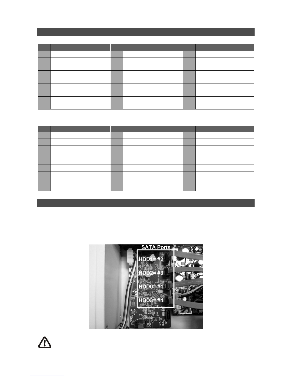
Install HDDs
Users can install up to 4 HDDs to create a preferred RAID disk type. Note the SATA port numbers
on the SATA board (as shown in below figure) are linked to the indication numbers in the OSD
menu.The installed HDDs must be the same storage capacity, and it is strongly recommended to
use HDDs of the same model. Please refer to the following steps to install HDDs into the DVR.
NOTE: Please avoid using Seagate SV35 series and WD AVGP series HDDs.
4
Release the screws and remove the cover of the Versatile H.264 DVR.
First fix the HDDs onto the mounting kits. Then connect the power and SATA cables to the HDDs
and fix the HDDs onto the bottom of the DVR.
Connect the SATA cables to the SATA ports on the SATA board.
Put the cover back to the DVR and connect the power cord and required equipments.
For users who are not familiar with RAID disk types, please read the next section about facts of
different RAID disk types BEFORE creating the RAID disk in the DVR.
RAID Disk Types
RAID, the acronym for Redundant Array of Independent Disks, is a data storage scheme that stores
data dispersedly in multiple disks to prevent data loss. The DVR provides three different types of
RAID disks: RAID 0, RAID 1, and RAID 10. Refer to the description listed below, users can choose
their preferred RAID disk types.
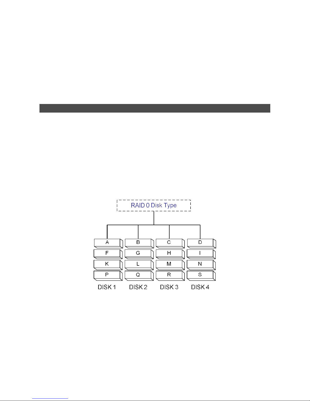
RAID 0:
Data in RAID 0 will be separately stored in a minimum of 2 different disks. This helps to increase
writing speed. The order of how data blocks are stored is illustrated as below. RAID 0 is not fault
tolerable. Just ONE disk failure in ANY disk of the array will destroy everything in the database.
 Loading...