

DynaColor 960H H.264 DVR Setup Manual
000ASL61Z100 1
960H H.264 DVR
Setup Guide
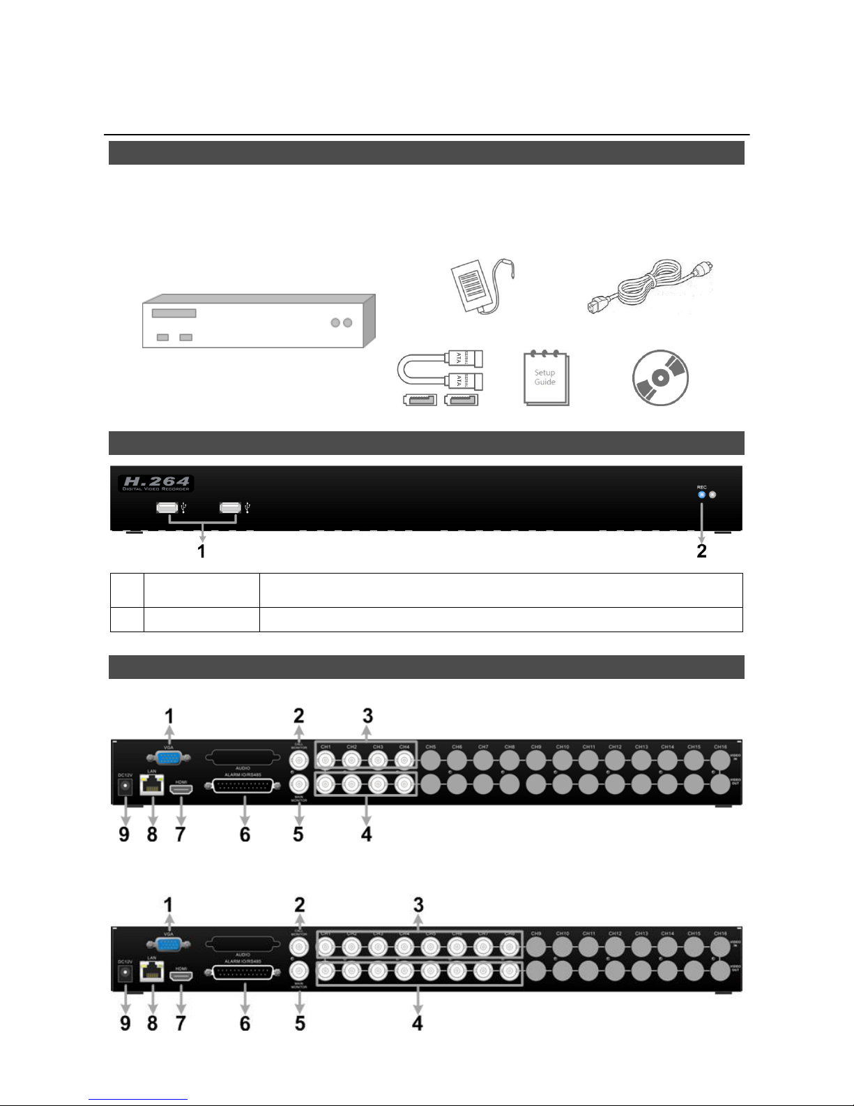
Package Content
Inspect the packaging carton. Make sure the 960H H.264 DVR is properly delivered. Remove all
items from the box and make sure the box contains the following items.
960H H.264 DVR
Power Adaptor
Power Cord
SATA Cable
Setup Guide
Software CD
Front Panel
1
USB 2.0 Port*2
The USB 2.0 ports allow users to connect external USB devices to the
unit, such as a USB ThumbDrive or a USB mouse.
2
Record LED
It blinks when videos are being recorded.
Rear Panel
4CH models:
8CH models:
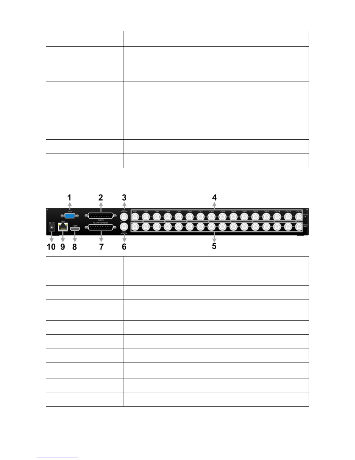
2
1
Main Monitor
(VGA)
A VGA output connector is offered for connecting to a VGA main
monitor.
2
Call Monitor
(BNC)
A BNC connector is provided for connecting to a call monitor.
3
Video In (BNC)
A group of BNC connectors is provided for video input streams from
installed cameras. The number of connectors equals to the number
of channels.
4
Video Out (BNC)
The same amount of BNC connectors beneath Video In (BNC) are
offered for looping out the video input.
5
Main Monitor
(BNC)
A BNC connector is provided for connecting to a main monitor.
6
Alarm I/O, RS-485 &
Audio In
The DVR provides alarm I/O, RS-485 & Audio In ports that offer
users the flexibility to connect the unit to other devices.
7
Main Monitor
(HDMI)
An HDMI connector is provided for connection to a displaying
device that transmittss data digitally to show the best video quality.
8
LAN 10/100/1000M
(RJ-45)
The DVR is capable of networking, and it allows the videos to be
viewed over the LAN network or the Internet via internet browsers.
9
Power Jack
Connect the power supply cord shipped with the DVR. Use of other
power supply cords may cause overloading.
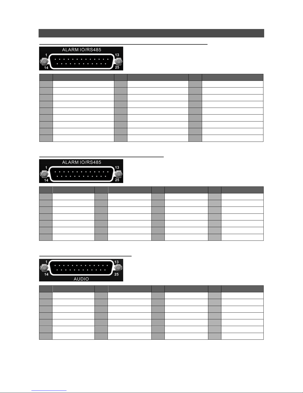
16CH models:
1
Main Monitor
(VGA)
A VGA output connector is offered for connecting to a VGA main
monitor.
2
Audio
An Audio connector is provided for connecting audio input devices
for all channels and audio ouput device for the Main monitor.
3
Call Monitor
(BNC)
A BNC connector is provided for connecting to a call monitor.
4
Video In (BNC)
A group of BNC connectors is provided for video input streams from
installed cameras. The number of connectors equals to the number
of channels.
5
Video Out (BNC)
The same amount of BNC connectors beneath Video In (BNC) are
offered for looping out the video input.
6
Main Monitor
(BNC)
A BNC connector is provided for connecting to a main monitor.
7
Alarm I/O & RS-485
The DVR provides alarm I/O and RS485 ports that offer users the
flexibility to connect the DVR to other devices.
8
Main Monitor
(HDMI)
An HDMI connector is provided for connection to a displaying
device that transmits data digitally to show the best video quality.
9
LAN 10/100/1000M
(RJ-45)
The DVR is capable of networking, and it allows the videos to be
viewed over the LAN network or the Internet via internet browsers.
10
Power Jack
Connect the power supply cord shipped with the DVR. Use of other
power supply cords may cause overloading.
3
Pin Definition of Alarm I/O & RS-485, and Audio
Pin Definition of Alarm I/O & RS-485 and Audio In (4CH / 8CH models)
Pin
Definition
Pin
Definition
Pin
Definition
1
GND
10
Alarm In 1
19
Audio In 2
2
GND
11
RS485 D+
20
Alarm In 8 (8CH only)
3
Audio In 7 (8CH only)
12
Alarm Out COM
21
Alarm In 6 (8CH only)
4
Audio In 5 (8CH only)
13
Alarm Out Open
22
Alarm In 4
5
Audio In 3
14
GND
23
Alarm In 2
6
Audio In 1
15
Main Audio Out
24
RS485 D−
7
Alarm In 7 (8CH only)
16
Audio In 8 (8CH only)
25
Alarm Out Close
8
Alarm In 5 (8CH only)
17
Audio In 6 (8CH only)
9
Alarm In 3
18
Audio In 4
Pin Definition of Alarm I/O & RS-485 (16CH models)
Pin
Definition
Pin
Definition
Pin
Definition
Pin
Definition
1
Alarm Out Open
8
Alarm In 3
15
Reserved
22
Alarm In 13
2
Alarm Out COM
9
Alarm In 4
16
Reserved
23
Alarm In 14
3
RS485 D+
10
Alarm In 5
17
Reserved
24
Alarm In 15
4
RS485 D−
11
Alarm In 6
18
Alarm In 9
25
Alarm In 16
5
Reserved
12
Alarm In 7
19
Alarm In 10
6
Alarm In 1
13
Alarm In 8
20
Alarm In 11
7
Alarm In 2
14
Alarm Out Close
21
Alarm In 12
Pin Definition of Audio (16CH models)
Pin
Definition
Pin
Definition
Pin
Definition
Pin
Definition
1
Audio In 1
8
Audio In 15
15
Audio In 4
22
GND
2
Audio In 3
9
GND
16
Audio In 6
23
GND
3
Audio In 5
10
GND
17
Audio In 8
24
GND
4
Audio In 7
11
GND
18
Audio In 10
25
Reserved
5
Audio In 9
12
Reserved
19
Audio In 12
6
Audio In 11
13
Main Audio Out
20
Audio In 14
7
Audio In 13
14
Audio In 2
21
Audio In 16
4
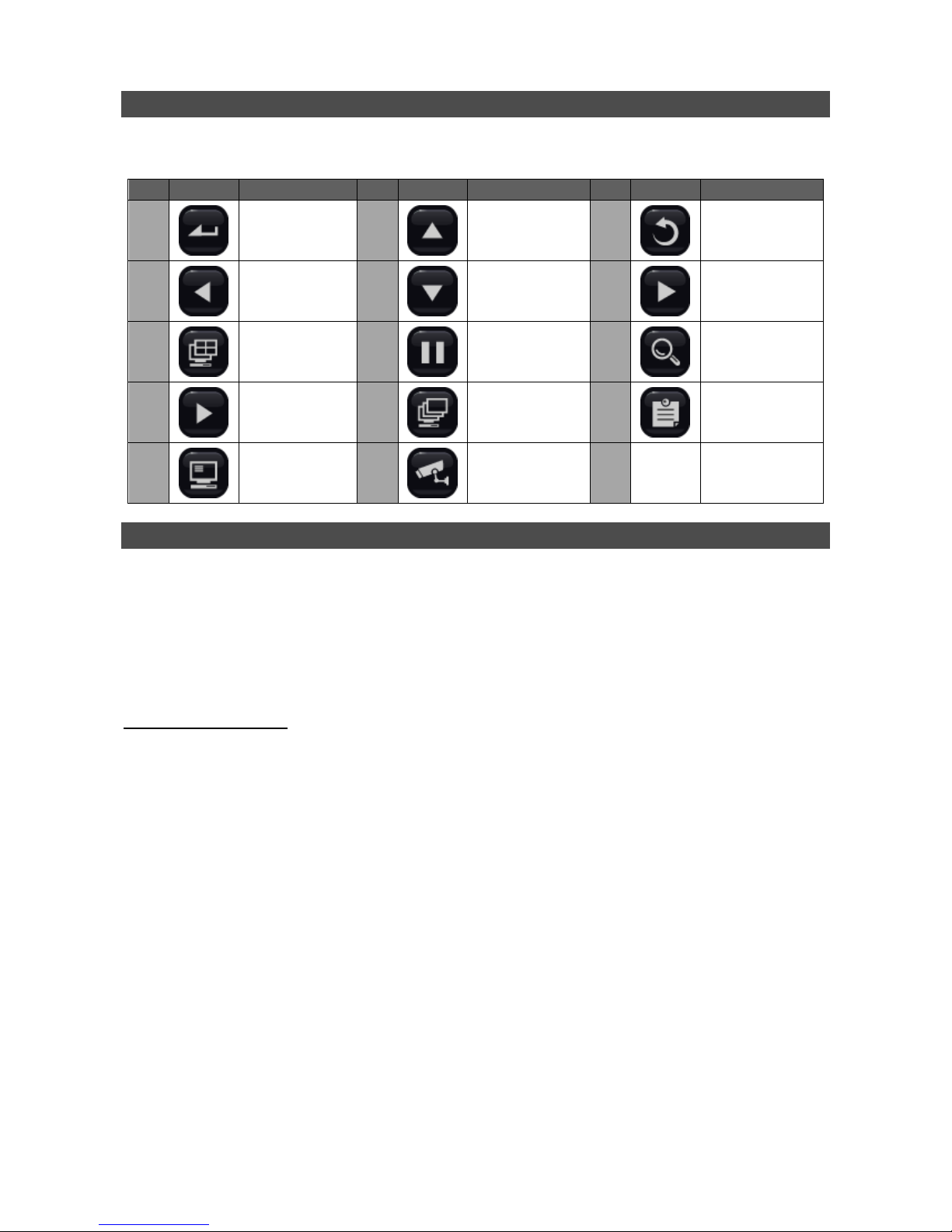
Live Panel Buttons
The functional buttons are displayed in the Live Panel when the mouse pointer moves to the right of
the screen. Refer to the table below for definition of each button.
Item
Icon
Description
Item
Icon
Description
Item
Icon
Description
1 Enter
2 Up
3 Esc
4 Left
5 Down
6 Right
7 Mode
8 Freeze
9 Search
10 Play/Stop
11 Sequence
12 Menu
13 Call Monitor
14
Dome Camera
Control
Power On the DVR
Please follow the proper power-on procedures to avoid damaging the DVR.
Connect all necessary components, e.g. monitor, USB mouse, and cameras, before power on
the DVR.
Check the type of power source before plugging in the power cord to the DVR. The acceptable
power input is between AC110V ~ AC240V.
Select Viewing Mode:
Click on MODE repeatedly to select the preferred display mode. The available viewing modes
are full-screen, 4-window, 9-window, and 16-window.
Click on FREEZE to pause the current viewing image.
 Loading...