


Full HD Multiple Streams
Micro Box IP Camera (Wireless)
User’s Manual
Ver. 1.2
001B0HWXZ2A2-WiFi

1
Table of Contents
1. Overview ................................................................................................................................ 2
1.1 Features ...................................................................................................................... 2
1.2 Package Contents ....................................................................................................... 3
1.3 Dimensions .................................................................................................................. 4
1.4 Connectors .................................................................................................................. 4
2. Camera Cabling ..................................................................................................................... 5
2.1 Connect Power ............................................................................................................ 5
2.2 Wireless LAN Connection Status ................................................................................. 5
2.3 Connect Alarm I/O ....................................................................................................... 5
3. System Requirements .......................................................................................................... 6
4. Access Camera ..................................................................................................................... 7
4.1 Camera Connection Setup ........................................................................................... 7
4.2 Device Search ........................................................................................................... 14
5. Setup Video Resolution ...................................................................................................... 17
6. Configuration Files Export / Import ................................................................................... 18
Appendix A: Technical Specification ........................................................................................ 19
Appendix B: Delete the Existing DC Viewer ................................ .............................................. 21
Appendix C: Setup Internet Security ......................................................................................... 22

2
1. Overview
The Full HD Multiple Streams Micro Box Wireless IP Camera is not only an easy
setup camera, but a versatile solution for homes and small offices. Users can
install the Wireless IP Camera in any place with Wi-Fi access. In addition, the
Wireless IP Camera has built-in microphone and speaker which allows two-way
audio communication. For low light environments, the Wireless IP Camera has
incorporated Day/Night ICR technologies to capture clear images. 2 Megapixel
resolution is supported for providing high definition images. Quad Streams
Compression (H.264 Baseline / Main / High Profile + MJPEG) are available for
efficient bandwidth and storage management. Users now can remotely and
clearly watch over their families and homes via mobile devices while they are at
work or even traveling.
1.1 Features
Progressive Scan CMOS Sensor
2M Resolution
Quad Streams Support
Dual streams- Full HD 1080P Real-Time + D1 Real-Time
Quad Streams Compression- H.264 Baseline / Main / High Profile + MJPEG
Multi-language Support
Wide Dynamic Range
Wireless Network Support
Built-In Microphone and Speaker*
Motion Detection
Privacy Masks
Smart Picture Quality / 3D Noise Reduction
Smart IR Mode
Day/Night (ICR)
IR LED Module (working distance up to 5 m)*
microSD Support
ONVIF Support
(*) Optional
3
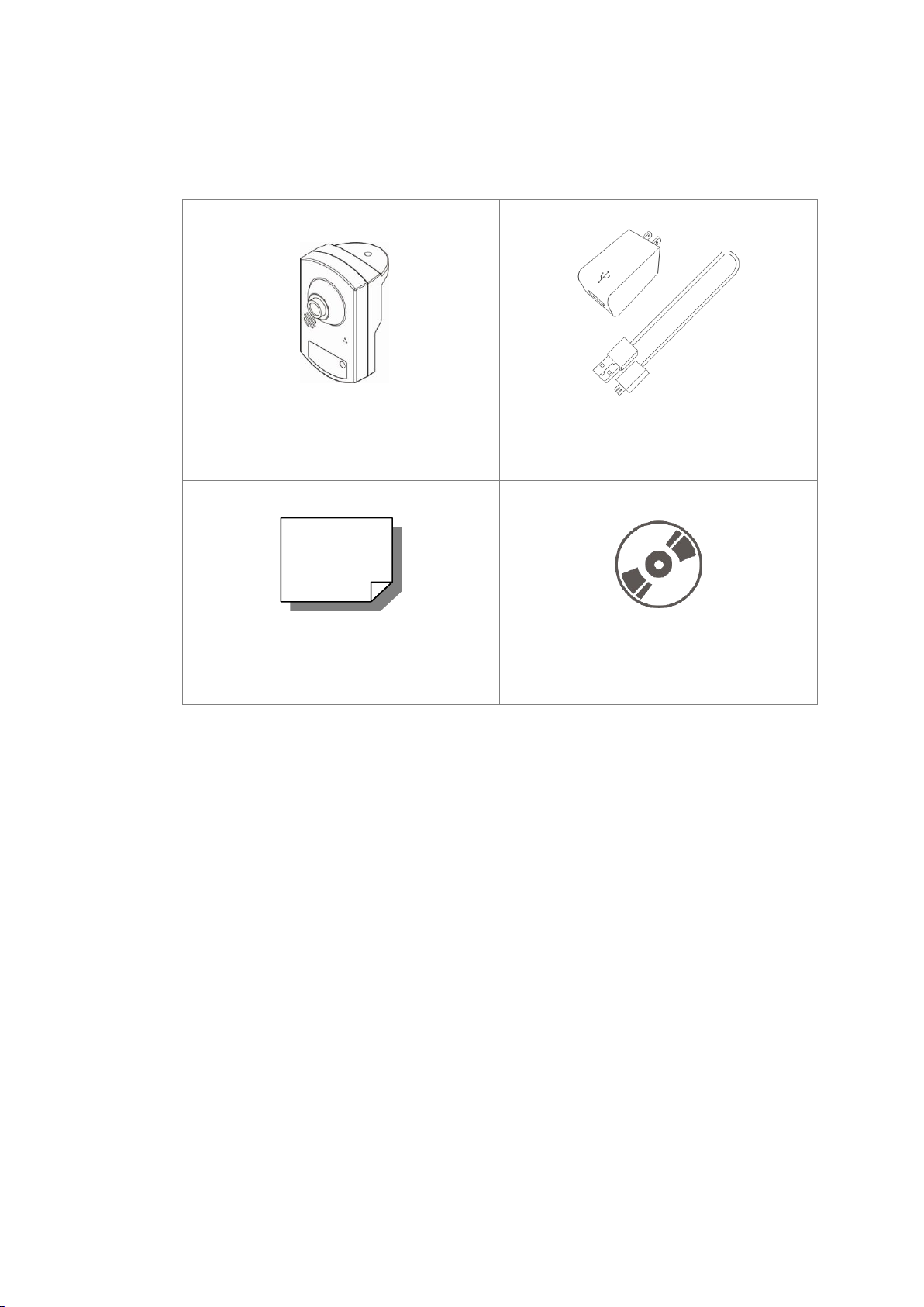
1.2 Package Contents
Full HD Multiple Streams Micro Box
Wireless IP Camera
Micro USB Power Supply Adapter &
Micro USB Cable
Quick Guide
CD
(bundled software and documentation)
Please check the package contains the following items listed below.
4
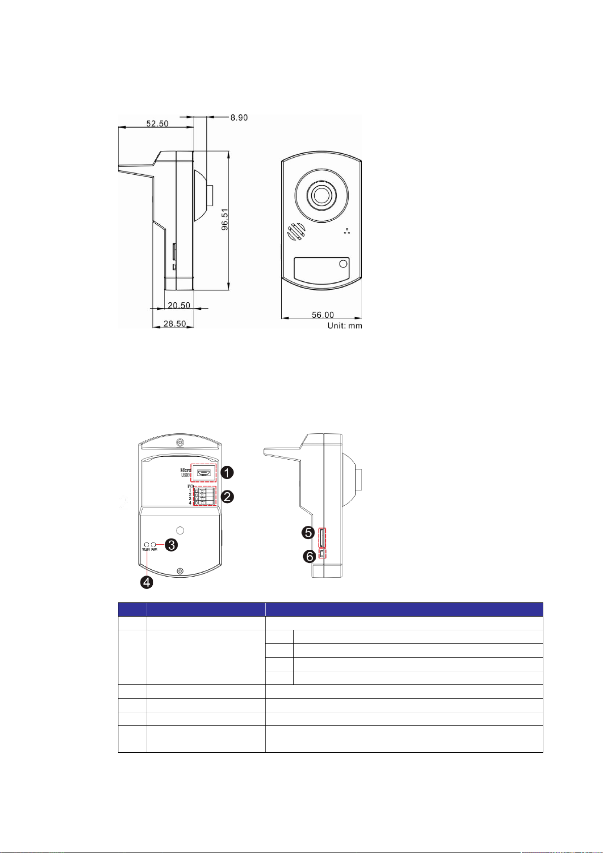
1.3 Dimensions
No.
Connector
Definition
1
Micro USB Port
For Power connection
2
Alarm I/O
1
Alarm Output +
2
Alarm Output −
3
Alarm Input +
4
Alarm Input −
3
Power LED
Power indication
4
WLAN LED
Wireless network connection and activity indication
5
microSD Card Slot
For videos and snapshots storage
6
Default Button
Press the button with a proper tool for at least 20
seconds to restore the system.
The dimensions of the IP Camera are shown below.
1.4 Connectors
The diagrams below show the connectors of the IP Camera. Definition for each
connector is also given as follows.
5
2. Camera Cabling
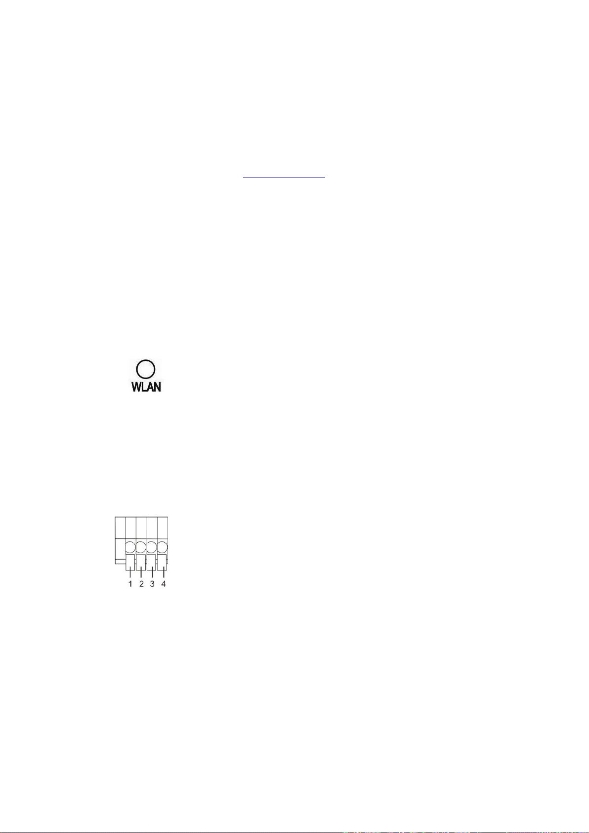
The LED in orange light indicates good network connection.
PIN 1: Output +
PIN 2: Output −
PIN 3: Input +
PIN 4: Input −
Please follow the instructions below to complete IP Camera connection.
2.1 Connect Power
Please refer to section 1.4 Connectors. Plug the camera’s Micro USB Power
Supply Adapter connecting with the Micro USB cable into the power outlet, and
connect the other end of the cable to the camera’s Micro USB port. Alternatively,
connect the Micro USB Cable to the Micro USB port of the camera and plug the
other end of the cable into the USB port of the computer.
2.2 Wireless LAN Connection Status
Check the status of the Wireless LAN (WLAN) LED. If the LED is unlit, please
check if the camera is connected to the network.
2.3 Connect Alarm I/O
The camera equips one alarm input and one relay output for alarm application.
Refer to alarm pin definition below to connect alarm devices to the IP Camera if
needed.

6
3. System Requirements
Items
System Requirement
Personal Computer
1. Intel® Pentium® M, 2.16 GHz or
Intel® CoreTM2 Duo, 2.0 GHz
2. 2 GB RAM or more
Operating System
Windows XP / Windows VISTA / Windows 7 / Windows 8
Web Browser
Microsoft Internet Explorer 10 or later
Firefox
Chrome
Safari
Network Card
10Base-T (10 Mbps) or 100Base-TX (100 Mbps) operation
Viewer
ActiveX control plug-in for Microsoft IE
To perform the IP Camera via web browser, please ensure the PC is in good
network connection, and meet system requirements as described below.

7
4. Access Camera
The configuration of the initial camera connection will be introduced in section
4.1 Camera Connection Setup. After users completed the settings of the IP
Camera connection, users can use the device search tool, “Device Search”, to
search the camera in LAN, and connect to the Browser-based Viewer of the IP
Camera. Detailed information is in section 4.2 Device Search.
4.1 Camera Connection Setup
Before accessing the IP Camera, the initial connection setting of the IP Camera
must be setup. However, with different ways of powering on the IP Camera,
camera connection will also be configured differently. The following describes
how to setup the IP Camera via the Power Adapter Connection and USB
Connection.
Power Adapter Connection Setup
When the IP Camera is powered on with the power adapter, the camera is an
Access Point (AP) by default. As an AP, the camera serves as central
transmitter and receiver of Wi-Fi signals. In this case, users have to switch the
IP Camera from an AP to a WiFi device. Otherwise, the camera cannot be
performed as a surveillance camera. Follow the steps below to switch the IP
Camera from an AP to a WiFi device.
Step 1: Power on the IP Camera with the power adaptor.
Step 2: Enable WLAN on users’ computer or laptop.
Step 3:
Step 4: Double click on <WiFiCamera> to connect the Access Point. The
Click on the internet connection icon < > at the bottom-right of the
taskbar, a list of Access Points will be displayed.
default password of the AP is 87654321.
Step 5: Open a web browser and enter the default IP address of the IP
Camera, 192.168.0.1. Then input the default username / password
(Admin / 1234).

8
Step 6: After the Browser-based Viewer is displayed, click on the <WiFi> tab
to connect the IP Camera to an Access Point.
Step 7: Under <Set WiFi camera connected to an Access Point>, select a
preferred Access Point and enter its password, and then click
<Connect>. See the figure below.
Step 8: Click <OK> in the prompt window.
Step 9: A message window will be displayed, click <Yes> to close the
Browser-based Viewer.
The IP address of the IP Camera will be altered. Thus, users have to re-search
the new IP address of the IP Camera by running the device search tool. After
retrieving the new IP address of the IP Camera, users can continue to access
and setup other settings of the camera.
NOTE: For further information about the device search tool, please refer
to section 4.2 Device Search.

9
USB Connection Setup
If the power of the IP Camera is supplied via the USB port of a computer, users
have to install the IP Camera driver (RNDIS/Ethernet Gadget driver) to the
computer. The following describes how to install the driver and setup the IP
Camera network connection settings.
Step 1: Connect the IP Camera to the USB port of the computer.
Step 2: Click on <Start>, type <cmd> in the search bar and select cmd.exe.
Then, input <ipconfig>. Note down the IP address under Local Area
Connection.
Step 3: Right click on the Computer icon on the desktop, and then select
<Properties> → <Device Manager>.
Step 4: Double click on <RNDIS/Ethernet Gadget> under <Other devices>.

10
Step 5: The RNDIS/Ethernet Gadget Properties window will be displayed.
Click <Update Driver…>.
Step 6: Select <Browse my computer for driver software>.
Step 7: Select <Let me pick from a list of…>.
Step 8: Double click on <Network adapters> under <Common hardware
types :>.
Step 9: Select Microsoft from the Manufacturer list first, and then select
Remote NDIS Compatible Device for Network Adapter. Click <Next>.
11
NOTE: For Windows 7 users, select Microsoft Corporation
from the Manufacturer list.
Step 10: A warning window will pop up. Click <Yes>.
Step 11: A message window from Windows will pop up, click <Close> to exit.
Step 12: Under the RNDIS/Ethernet Gadget Properties window, the Device
status will describe “The device is working properly.” Click <Close>
to exit.
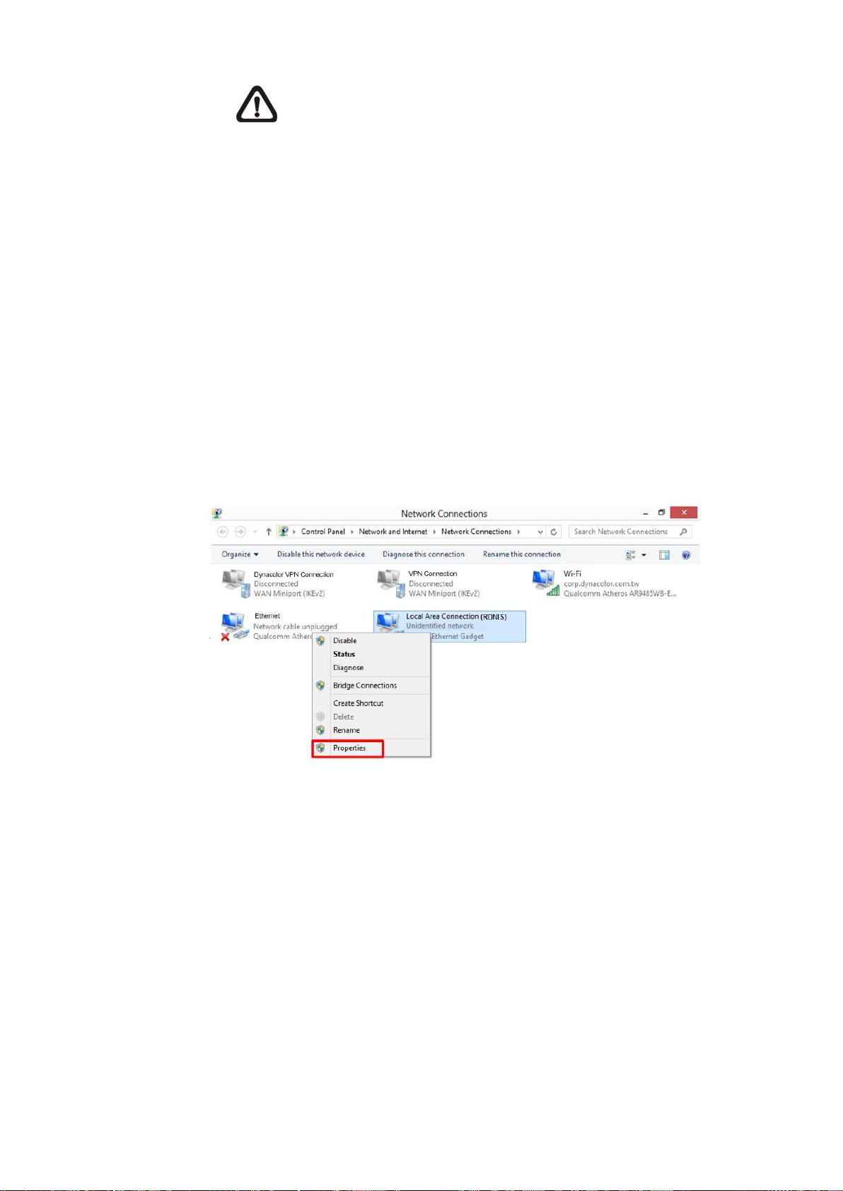
Step 13: Right click on the Network icon on the desktop, and then select
<Properties> → <Change adapter settings>.
Step 14: Right click on the Local Area Connection (RDNIS) icon, and select
<Properties>.
12
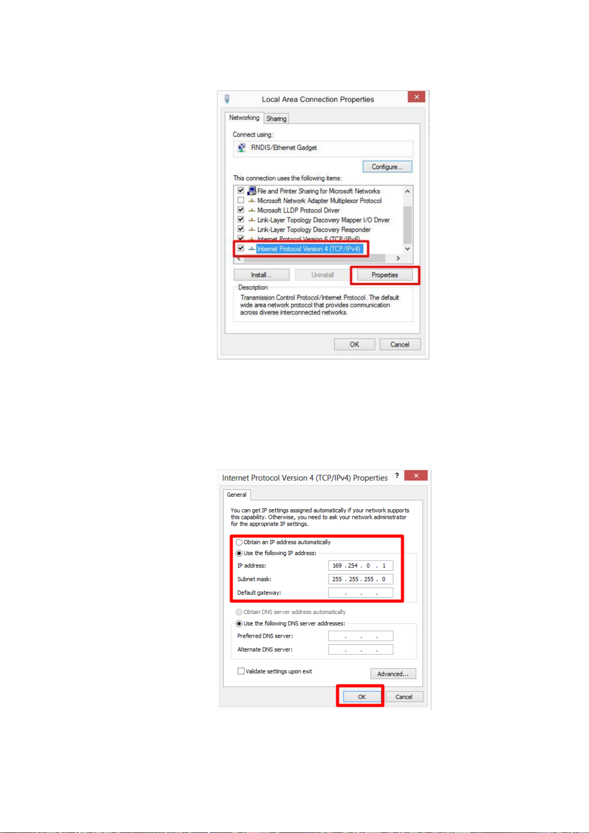
Step 15: Select Internet Protocol Version 4 (TCP/IPv4). Click <Properties>.
Step 16: Setup the IP address as the picture below. The IP address must be:
169.254.0.XXX. Note that the range of the last decimal number “XXX”
is from 1 to 249. Subnet must be: 255.255.255.0. After finishing the
settings, click <OK> to exit.
Step 17: Click <Close> to exit the Local Area Connection Properties window.

13
After the above settings are completed, the last step is to go to the camera’s
Browser-Based Viewer to connect the camera to an Access Point. Open a web
browser and enter the default IP address of the IP Camera (169.254.0.250).
Next, please follow the same instruction from Step 6 to Step 9 in previous
subsection, Access Point Connection Setup.
The IP address of the IP Camera will be altered. Thus, users have to re-search
the new IP address of the IP Camera by running the device search tool. After
retrieving the new IP address of the IP Camera, users can continue to access
and setup other settings of the camera.
NOTE: Before accessing the camera, users MUST modify the IP
address of the computer to its original IP address, which users
previously noted down. Otherwise, users cannot access the camera.
NOTE: For further information about the device search tool, please refer
to the next section, 4.2 Device Search.

14
4.2 Device Search
Login ID
Password
Admin
1234
To access the IP Camera, users can search the camera through the installer
program: DeviceSearch.exe, which can be found in “DeviceSearch” folder in the
supplied CD.
Accessing the Camera by Device Search Software
Step 1: Double click on the program Device Search.exe. After its window
appears, click on the <Device Search> button on the top side.
Step 2: All found IP devices will be listed in the Device Search page. Find the
IP Camera by its MAC address.
NOTE: Users can check the MAC address of the IP Camera
from the sticker on the package.
Step 3: Double click or right click and select <Browse> to access the camera
directly via web browser.
Step 4: A Prompt window requesting for default username and password will
appear. Enter the default username and password shown below to
login to the IP Camera.
NOTE: ID and password are case sensitive.
NOTE: It is strongly advised that administrator’s password be
altered for the security concerns. Refer to Full HD Multiple
Streams IP Camera Menu Tree for further details.

15
Installing DC Viewer Software Online
For initial access to the IP Camera, a client program, DC Viewer, will be
automatically installed on the PC when connecting to the IP Camera.
If the Web browser does not allow DC Viewer installation, please check the
Internet security settings or ActiveX controls and plug-ins settings (refer to
chapter Appendix C: Setup Internet Security) to continue the process.
The Information Bar (just below the URL bar) may come out and ask for
permission to install the ActiveX Control for displaying video in browser. Right
click on the Information Bar and select <Install ActiveX Control…> to allow the
installation.
The download procedure of DC Viewer software is specified as follows.
Step 5: In the DC Viewer installation window, click on <Next> to start
installation.
Step 6: The status bar will show the installation progress. After the installation
is completed, click on <Finish> to exit the installation process.
Step 7: Click on <Finish> to close the DC Viewer installation page.
16
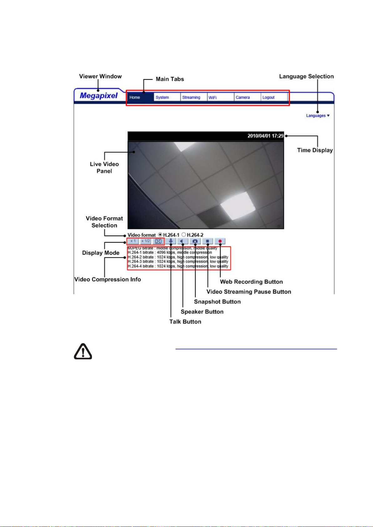
Once the DC Viewer is successfully installed, the IP Camera’s Home page will
be able to correctly display as the figure below.
NOTE: Please refer to Full HD Multiple Streams IP Camera Menu Tree
for more button function detail.

17
5. Setup Video Resolution
2M
H.264- 1920 x 1080 (30 fps) + H.264- 720 x 480 (30 fps)
Users can setup Video Resolution on the Video Format page of the user-friendly
browser-based configuration interface.
Video Format can be found under this path: Streaming> Video Format.
The default value of Video Resolution is as below.
For more Video Resolution combination details, please refer to chapter
Appendix D: Video Resolution. Click on <Save> to confirm the setting when
finish setting up the video resolution.

18
6. Configuration Files Export / Import
To export / import configuration files, users can access the Maintenance page
on the user-friendly browser-based configuration interface.
The Maintenance setting can be found under this path: System> Maintenance.
Users can export configuration files to a specified location and retrieve data by
uploading an existing configuration file to the IP Camera. This is especially
convenient to make multiple cameras having the same configuration.
Export
Users can save the system settings by exporting the configuration file (.bin) to a
specified location for future use. Click on the <Export> button, and the popup
File Download window will come out. Click on <Save> and specify a desired
location for saving the configuration file.
Upload
To upload an existing configuration file to the IP Camera, please first click on
<Browse> to select the configuration file, and then click on the <Upload> button
for uploading.

19
Appendix A: Technical Specification
Camera
2M
2M Real-Time
Image Sensor
1/2.7” Progressive CMOS
Effective Pixels
1920 (H) x 1080 (V)
Minimum Illumination
TBD
White Balance
Manual / AWB / ATW
Shutter Speed
1 ~ 1/10000 sec.
Lens
Focal Length
2.8 mm / 3.6 mm
F Number
F 2.0 / F 1.8
Operation
Multiple Languages
English / French / German / Italian / Korean / Simplified Chinese /
Traditional Chinese / Russian / Portuguese / Spanish / Japanese
Image Setting
Backlight Compensation
On / Off
White Balance
Auto / Manual / ATW
Noise Reduction (3D)
On / Off
Wide Dynamic Range
On / Off
Privacy Mask
On / Off
Brightness
Manual
Exposure
Auto / Manual
Sharpness
Manual
Contrast
Manual
Saturation
Manual
Hue
Manual
Digital Zoom
Support
Motion Detection
On / Off / By Schedule
Privacy Mask Type
Color
ICR
Auto / On / Off / Smart
ICR + IR LED
Auto / LED On / LED Off / Smart IR / Light Sensor
Tampering Alarm
On / Off / By Schedule
Audio
Two-way Audio
Built-in Mic In / Built-in Speaker Out*
Compression
G.711 / G.726
Network
Interface
10/100Mbps / WiFi 802.11 b/g/n 2.4GHz
Video Compression
H.264 / MJPEG
Video Streaming
Dual Streams- H.264 + MJPEG / H.264 + H.264
Quad Streams- H.264 x 4 / H.264 x 3 + MJPEG
Video Resolution
H.264- Full HD 1080P / SXGA / HD 720P / XGA / SVGA / D1 / VGA / CIF
MJPEG- Full HD 1080P / SXGA / HD 720P / XGA / SVGA / D1 / VGA / CIF
Frame Rate
Dual Streams- 1080p (15/13 fps) +
720p (30/25 fps)
Dual Streams- 1080P (30/25 fps) +
D1 (30/25 fps)
Protocol
IPv4/v6, TCP/IP, UDP, RTP, RTSP, HTTP, HTTPS, ICMP, FTP, SMTP,
DHCP, PPPoE, UPnP, IGMP, SNMP, QoS, ONVIF
Security / Authorization
HTTPS / IP Filter / WEP / WPA / WPA2 Wireless Security
Alarm
Input
1 Set, 5V 10kΩ pull up
Output
1 Set, Photo Relay Output 300V DC/AC
Event Notification
HTTP / FTP / SMTP
microSD
microSDHC 32GB Support
Supported Web Browser
Internet Explorer (10.0+) / Chrome / Firefox / Safari
User Account
20
Password Levels
User and Administrator
Mechanical
Built-in IR
Illuminator*
Working distance
up to 5 m
Wavelength
850 nm
Number of LEDs
2
Power Connection
Micro USB (with 1A USB Adapter)
LED Indicator
Power (Green) / WiFi (Orange)
Connectors
Alarm
4 Pin Terminal Block (Female)
Power
Micro USB Port

20
General
Operating Temperature
-10°C ~ 50°C (14°F ~ 122°F)
Humidity
10% ~ 90%, No Condensation
Dimension
96.51 x 56.00 x 61.40 mm (3.78 x 2.20 x 2.42 in.)
Weight
120 g
Power Source
1A USB Adapter
Power Consumption
System: 3 W
(Built-in IR Illuminator: +0.8 W)
Regulatory
FCC / CE / LVD / RoHS
(*) Optional

21
Appendix B: Delete the Existing DC Viewer
For users who have installed DC Viewer in the PC previously, please first remove the
existing DC Viewer from the PC before accessing to the IP Camera.
Deleting the DC Viewer
In the Windows <Start Menu>, activate <Control Panel>, and then double click on <Add or
Remove Programs>. In the <Currently installed programs> list, select <DCViewer> and
click on the button <Remove> to uninstall the existing DC Viewer.
Deleting Temporary Internet Files
To improve browser performance, it is suggested to clean up all the files in the Temporary
Internet Files.
The procedure is as follows:
Step 1: In the web browser, click on the <Tools> tab on the menu bar and select <Internet
Options>.
Step 2: Click on the <Delete> button under <Browsing history> section. In the appeared
window, tick the box beside the <Temporary Internet Files>.
Step 3: Click on <Delete> to start deleting the files.

Appendix C: Setup Internet Security
If ActiveX control installation is blocked, please either set Internet security level to default or
change ActiveX controls and plug-ins settings.
Internet Security Level: Default
Step 1: Start the Internet Explorer (IE).
Step 2: Click on the <Tools> tab on the menu bar and select <Internet Options>.
Step 3: Click on the <Security> tab, and select <Internet> zone.
Step 4: Down the page, click on the <Default Level> button, and click on <OK> to confirm
the setting. Close the browser window, and restart a new one later to access the IP
Camera.
ActiveX Controls and Plug-ins Settings
Step 1: Repeat Steps 1~3 of the previous section above.
Step 2: Down the page, click on the <Custom Level> button to change ActiveX controls
and plug-ins settings. The Security Settings window will pop up.
Step 3: Under <ActiveX controls and plug-ins>, set ALL items (as listed below) to
<Enable> or <Prompt>. Please note that the items vary by IE version.
ActiveX controls and plug-ins settings:
1. Binary and script behaviors.
2. Download signed ActiveX controls.
3. Download unsigned ActiveX controls.
4. Allow previously unused ActiveX controls to run without prompt.
5. Allow Scriptlets.
6. Automatic prompting for ActiveX controls.
7. Initialize and script ActiveX controls not marked as safe for scripting.
8. Run ActiveX controls and plug-ins.
9. Only allow approved domains to use ActiveX without prompt.
10. Script ActiveX controls marked safe for scripting*.
11. Display video and animation on a webpage that does not use external media player.
Step 4: Click on <OK> to accept the settings. A prompt window will appear for confirming
the setting changes, click <Yes(Y)> and close the Security Settings window.
Step 5: Click on <OK> to close the Internet Options screen.
Step 6: Close the browser window, and restart a new one later to access the IP Camera.
22

This device complies with Part 15 of the FCC Rules.
Operation is subject to the following two conditions:
(1) this device may not cause harmful interference, and
(2) this device must accept any interference received, including interference
that may cause undesired operation.
CAUTION: Changes or modifications not expressly approved by the party
responsible for compliance could void the user's authority to operate the
equipment.
The users manual or instruction manual for an intentional or unintentional
radiator shall caution the user that changes or modifications not expressly
approved by the party responsible for compliance could void the user's
authority to operate the equipment. In cases where the manual is provided
only in a form other than paper, such as on a computer disk or over the
Internet, the information required by this section may be included in the
manual in that alternative form, provided the user can reasonably be
expected to have the capability to access information in that form.
NOTE: This equipment has been tested and found to comply with the limits
for a Class B digital device, pursuant to Part 15 of the FCC Rules. These limits
are designed to provide reasonable protection against harmful interference
in a residential installation.
This equipment generates, uses and can radiate radio frequency energy and,
if not installed and used in accordance with the instructions, may cause
harmful interference to radio communications.
However, there is no guarantee that interference will not occur in a particular
installation. If this equipment does cause harmful interference to radio or
television reception, which can be determined by turning the equipment off
and on, the user is encouraged to try to correct the interference by one or
more of the following measures:
-- Reorient or relocate the receiving antenna.
-- Increase the separation between the equipment and receiver.
-- Connect the equipment into an outlet on a circuit different from that to
which the receiver is connected.
-- Consult the dealer or an experienced radio/TV technici
RF exposure warning
an for help.
This equipment must be installed and operated in accordance with provided
instructions and the antenna(s) used for this transmitter must be installed to
provide a separation distance of at least 20 cm from all persons and must not
be co-located or operating in conjunction with any other antenna or
transmitter. End-users and installers must be provided with antenna
installation instructions and transmitter operating conditions for satisfying RF
exposure compliance.
 Loading...