

Updatemydynaco
Dynaco SCA80(Q)
Amplifier and Power Supply Upgrade
(PWRAMP80)
ASSEMBLY MANUAL
© 2016-2017 AkitikA LLC
All rights reserved
Revision 1p18 November 25, 2017
Page 1 of 36

Table of Contents
Table of Contents ................................................................................................................ 2
Table of Figures .................................................................................................................. 3
Section 1: About This Manual ............................................................................................ 4
Who Should Attempt this Project? ................................................................................. 4
Tools you’ll need ............................................................................................................ 4
Helpful Tools .................................................................................................................. 4
Project Overview ............................................................................................................ 4
Important Safety Notes ................................................................................................... 5
About Components ......................................................................................................... 5
Recommended Solder ..................................................................................................... 5
Warranty ......................................................................................................................... 5
Section 2: Kit Building Hints .............................................................................................. 6
Section 3: Building the Power Supply ................................................................................ 6
Component Order............................................................................................................ 7
Install the Resistors ......................................................................................................... 7
Install the diodes ............................................................................................................. 8
Install the optoisolator..................................................................................................... 9
Install the Transistors .................................................................................................... 10
Install the Small Non-polar Capacitors ......................................................................... 10
Install the Electrolytic (polarized) Capacitors .............................................................. 10
Fasten the Mounting Brackets to the PCB .................................................................... 10
Install the C9 Connection wires .................................................................................... 10
Install the RLYDRV wire ............................................................................................. 11
Check your work ........................................................................................................... 11
Disconnect the Old Power Supply and Power Amplifier ............................................. 11
SCA80Q .................................................................................................................... 12
SCA80 Directions ..................................................................................................... 13
Removing the Amplifier Modules, All Versions ...................................................... 13
Install the New Power Supply....................................................................................... 15
Test the New Power Supply .......................................................................................... 16
Section 4: Building the Stereo Amplifier Module ............................................................ 16
Install the diodes ........................................................................................................... 18
Install the Small Non-polar Capacitors ......................................................................... 19
Install the Electrolytic (polarized) Capacitors .............................................................. 19
Install the Transistors .................................................................................................... 20
Install the Relays ........................................................................................................... 20
Fasten the PCB to the Heatsink .................................................................................... 20
Install the LM3886 Power Amplifier ICs ..................................................................... 20
Build and Install the Inductor Resistor Combination ................................................... 21
Install the Red/Black Zipcord Power Wires ................................................................. 24
Install the Bonded Pair Capacitor Wires ....................................................................... 24
Install the auxiliary heatsink ......................................................................................... 24
Install the power amplifier ............................................................................................ 25
Test your work .............................................................................................................. 26
Page 2 of 36

Bare amplifier tests ................................................................................................... 26
Amplifier plus speaker tests ...................................................................................... 26
Amplifier plus speaker plus source tests ................................................................... 27
Final Assembly ............................................................................................................. 27
In Case of Trouble ........................................................................................................ 27
About the Design .......................................................................................................... 28
Power Supply Theory of Operation .......................................................................... 28
Amplifier Board Theory of Operation ...................................................................... 32
Table of Figures
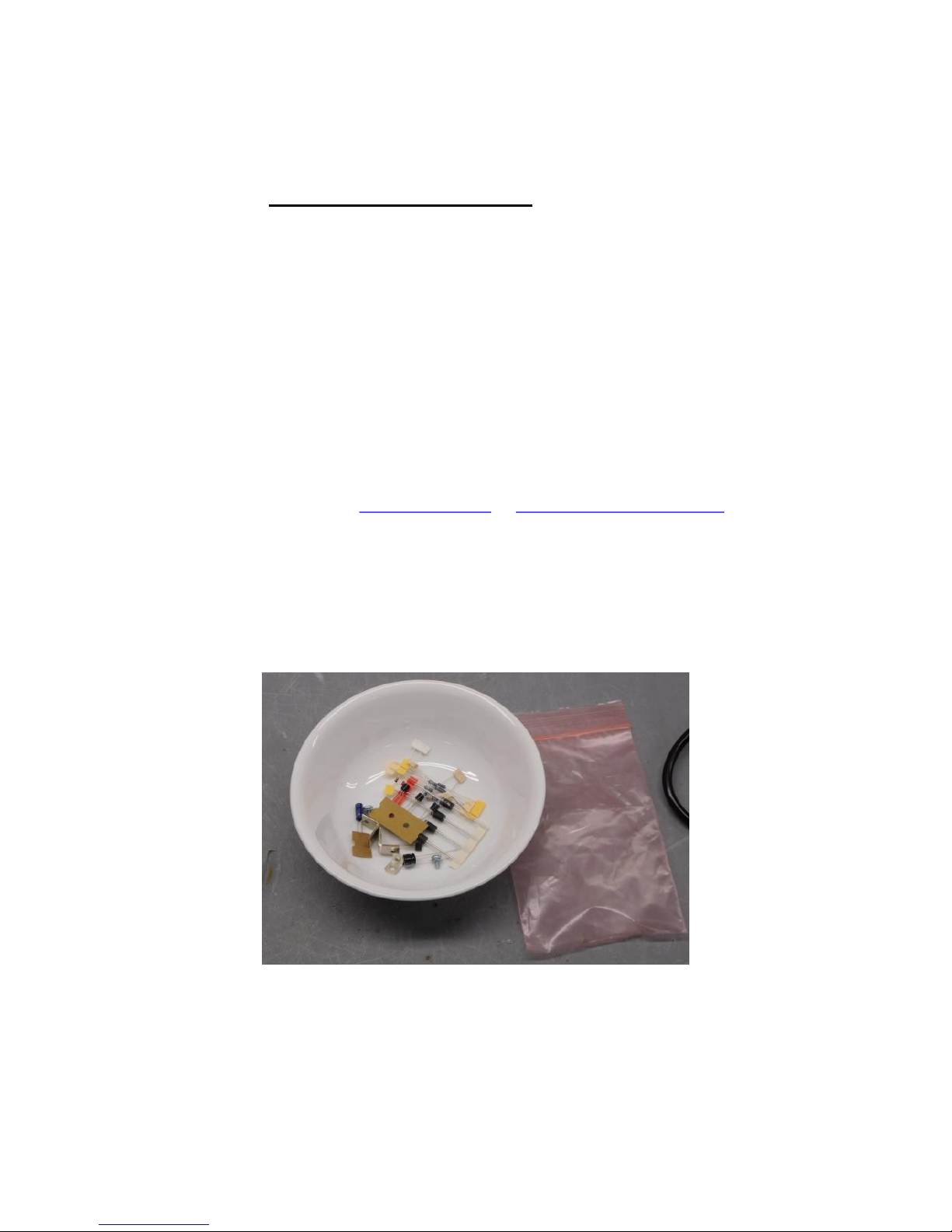
Figure 1-Empty the power supply components into a soup bowl ....................................... 6
Figure 2-Silk screen shows power supply component locations ........................................ 7
Figure 3-Pin 1 of the opto-isolator is indicated by the dot and the ridge in the package ... 9
Figure 4-Although more subtle, notice that the Q4 has a square side and a round side ..... 9
Figure 5-Installing the mounting brackets on the power supply PCB .............................. 10
Figure 6-Grounding arrangement for speaker common connections on the SCA-80 ...... 16
Figure 7-Component locations for the stereo amplifier module ....................................... 17
Figure 8-Anode is the longer of the two leads .................................................................. 19
Figure 9-Assembling the PCB to the heatsink .................................................................. 20
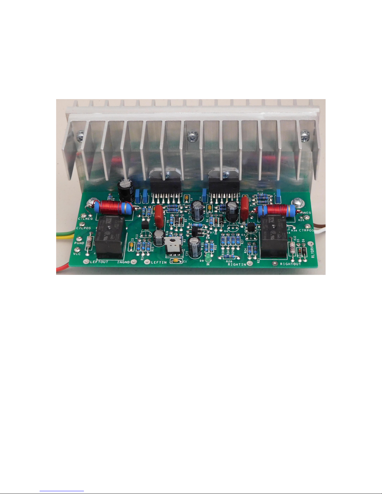
Figure 10-Assembled amplifier on main heatsink ............................................................ 21
Figure 11-Assembled PCB with both heatsinks attached ................................................. 25
Figure 12-Power supply snippet ....................................................................................... 29
Figure 13-DC Good Detector snippet ............................................................................... 30
Figure 14-AC Detect snippet ............................................................................................ 31
Figure 15-Power Supply Schematic.................................................................................. 34
Figure 16-Page 1 of Amplifier Board Schematic ............................................................. 35
Figure 17-Page 2 of amplifier board schematic ................................................................ 36
Page 3 of 36

Section 1: About This Manual
This manual gives the information needed to build and install the upgraded power supply
and amplifier modules for either Dynaco’s SCA-80(Q) Integrated Amp. The is another
manual that covers installation of this kit into a Stereo 80 Power Amp.
This kit upgrades the power amplifier and power supply sections. It’s also an easy
alternative to the rather difficult repair of the amplifier section of these units. The
resulting amp offers lower distortion and noise, a speaker relay for pop-free startup, It’s
also a cooler running, more efficient amplifier. The original amp modules dissipate 13
Watts at idle, all of it running through the 4 big power resistors. The new amp module
dissipates 8.6 Watts, but all of that power biases the output stage, greatly increasing its
linearity.
Who Should Attempt this Project?
You can build this kit if you can:
1. Solder (using normal rosin core solder and a soldering iron).
2. Use simple hand tools like screwdrivers, wire cutters, and pliers.
3. Read and follow directions.
It helps if you:
1. know a bit about electronics, or
2. have a friend who knows a bit about electronics
3. can get to YouTube to watch a few helpful videos about the assembly process
(none are posted as of this version of the manual).
Tools you’ll need
You’ll need the following tools:
1. Phillips screwdriver (#1 and #2), regular screw-drivers.
2. Pliers or nut drivers suitable for #4 and #6 hardware
3. needle nose pliers (helpful, but not strictly necessary)
4. pencil type soldering iron of 25 to 50 Watts (no huge honking soldering guns or
blowtorches)
5. wire cutters and strippers
6. multi-meter to measure power supply voltages and confirm resistor values
(strongly recommended)!
Helpful Tools
These tools aren’t strictly necessary, but make building the kit easier.
1. Magnifying glass, if you’re over 42!
2. Lead bending jig to form axial component leads to the correct span for insertion in
the PCB.
Project Overview
The project consists of the following steps:
1. Building the circuit boards.
Page 4 of 36

2. Removing the old power supply
notification.
3. Installing and testing the new power supply
4. Installing and testing the new power amplifier
5. Completing re-assembly of the amplifier.
Important Safety Notes
By purchasing, using, or assembling this kit, you have agreed to hold Akitika LLC
harmless for any injuries you may receive in its assembly and/or use. To prevent injuries:
Wear safety glasses when soldering or clipping wires to prevent eye injuries.
Always unplug the power before working on the amplifier.
Large capacitors hold lots of energy for a long time. Before you put your hands
into the amplifier:
o Pull the AC plug!
o Wait 2 full minutes for the capacitors to discharge!
Remove jewelry and rings from your hands and wrists, or anything that might
dangle into the amplifier.
If working one the equipment with the power on, keep one hand in your pocket,
especially if you’re near the power supply or power supply wires. This can
prevent serious shocks.
Build with a buddy nearby. If you’ve ignored all the previous advice, they can
dial 911 or get you to the hospital.
Read and understand the safety manuals of all the tools you use.
About Components
We reserve the right to make design/or component changes at any time without prior
Recommended Solder
The kit must be assembled with 60/40 Rosin Core solder. The recommended diameter is
0.032 inches. Among many such sources of solder, I have used Radio Shack part number
64-009. It contains 8 oz. of solder, which is much more than you’ll need to assemble this
kit.
Warranty
With the exception of fuses, Akitika LLC will replace for free any parts of a correctly
assembled product that fails within one year of the date of purchase when the equipment
has been used in home stereo applications. It is the responsibility of the kit builder to
install the replacement part(s). This warranty applies to the original purchaser only. It
does not apply to units that have been physically or electrically abused, modified without
prior factory authorization, or assembled with other than 60/40 Rosin Core solder.
Akitika LLC’s liability shall in no event exceed the cost paid to Akitika LLC for the kit.
Page 5 of 36
Section 2: Kit Building Hints
Yes, I know you want to ignore this section, and jump right into building the kit.
However, please take a minute and read the advice. I’ve condensed it into bullets so that
even you guys who are in a hurry can benefit.
Stop any time you’re feeling confused, tired, or anxious. Taking breaks at those
strategic times will keep the build enjoyable and greatly enhance your chances of
first-time success.
A soup bowl is your friend. Before you build a board, carefully empty the parts
for just that board into a broad, flat, light colored soup bowl. That makes it easy to
find the parts, and keeps them from getting lost.
A digital ohm-meter is an easy way to make sure that you’ve picked the right
resistor. It’s a great cross-check on the resistor color code. Measure twice and
solder once!
A lead-bending jig can make for quicker, neater assembly. It’s certainly not
necessary.
Is something in this manual confusing? Does something look wrong? Send your
questions by email to dan@akitika.com or dan@updatemydynaco.com. You’ll
help yourself and everyone who builds the kit.
Section 3: Building the Power Supply
This section details the process of building the power supply circuit board. Begin by
carefully emptying the contents of the Power Supply parts envelope into a broad soup
bowl, as shown below. In general, you’ll start with the components that lay closest to the
board, working your way towards the taller components.
Figure 1-Empty the power supply components into a soup bowl
Page 6 of 36
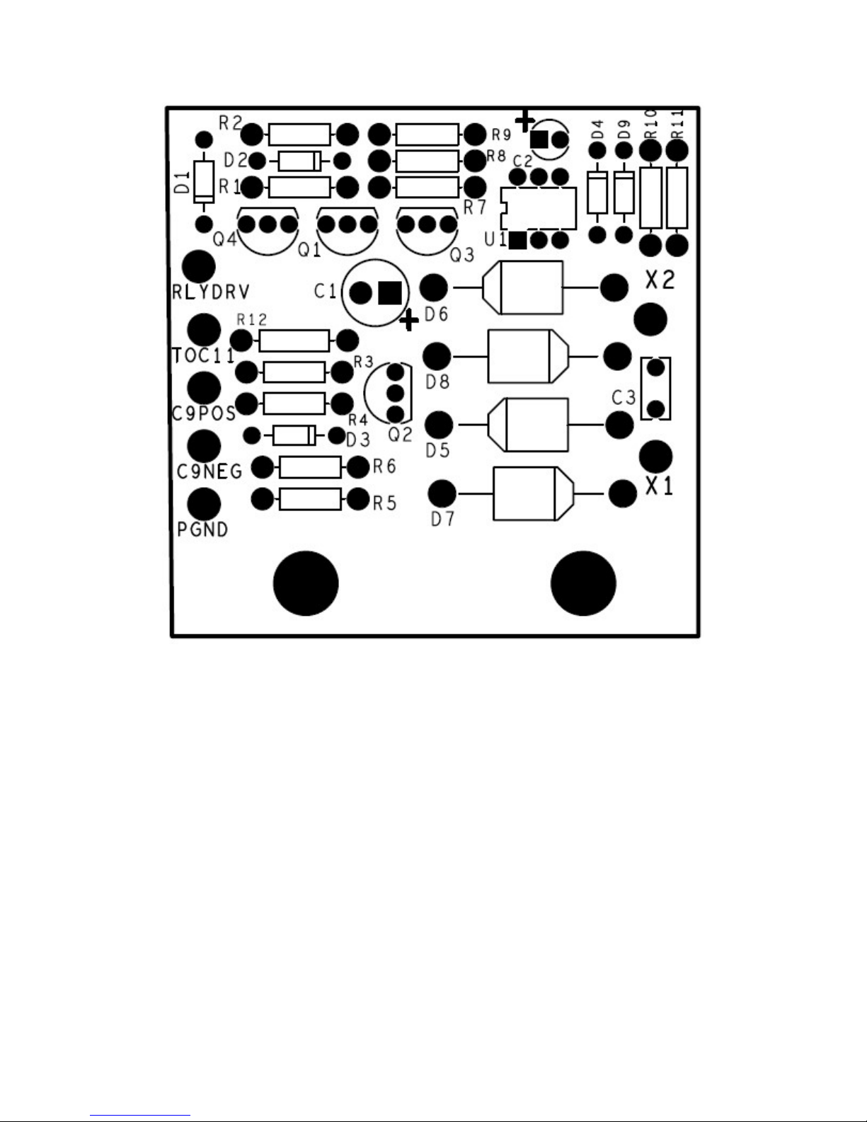
Figure 2-Silk screen shows power supply component locations
Component Order
You’ll notice that the component designations in the directions don’t go exactly in order.
We have grouped them so that all components with the same value appear together. This
makes assembly easier. You’ll find in the parts kit that similar parts, e.g. 3 1K resistors,
are typically (though not always) taped together.
Install the Resistors
In general, you install axial leaded components (like the resistors) by placing the body on
the silk screen side of the board, and the leads through the indicated holes. Bend the leads
over on the back of the board to keep the resistors from falling out until your solder them
in place. Try to bend the leads in a direction that won’t lead to solder bridges between
traces that should remain disconnected.
We recommend the following procedure:
1. Insert all components of the same value or type
Page 7 of 36
2. Bend the leads as described above.
Bend resistor leads to
0.45” width
Designation
Value
Color Code
Done
()
R1 1 Meg
Brown, Black, Black, Yellow, Brown
R3 1 Meg
Brown, Black, Black, Yellow, Brown
R4 100K
Brown, Black, Black, Orange, Brown
R6 10K
Brown, Black, Black, Red, Brown
R10 20K
Red, Black, Black,
Red, Brown
R5 40K2
Yellow, Black, Red, Red, Brown
R2 49K9
Yellow, White, White, Red, Brown
R11 49K9
Yellow, White, White, Red, Brown
R7 511K
Green, Brown, Brown, Orange, Brown
R8 511K
Green, Brown, Brown, Orange, Brown
R9 511K
Green, Brown, Br
own, Orange, Brown
R12 68, 1 Watt
, r% Blue, Gray, Black, Gold
All resistors are ¼ W 1% metal film unless otherwise indicated
Designation
Type
, Package
Rating, Marking
, Description
Done? (
)
D1 1N4148, DO
-35
100 PIV switching diode
D9 1N4148, DO
-35
100 PIV switching diode
D2 BZX7
9-B10, DO
-35
10V zener diode
, marked B10
D3 BZX79
-
B10, DO
-35
10V zener diode, marked B10
D4 BZX79
-
B10, DO
-35
10V zener diode, marked B10
D5 1N5404, DO
-
201AD
400 PIV, 3 Amp, rectifier diode
D6 1N5404, DO
-
201AD
400 PIV, 3 Amp, rectifier diode
D7 1N
5404, DO
-
201AD
400 PIV, 3 Amp, rectifier diode
D8 1N5404, DO
-
201AD
400 PIV, 3 Amp, rectifier diode
3. Solder the leads on the back of the board.
4. Clip the leads.
Track your progress by placing a check-mark in the done column as you install each
component.
Install the diodes
Diodes are polarized, having an anode and a cathode. When you insert the diode, match
the banded end of the diode to the banded end of its representation on the silk screen.
Diodes – watch the polarity!
Page 8 of 36
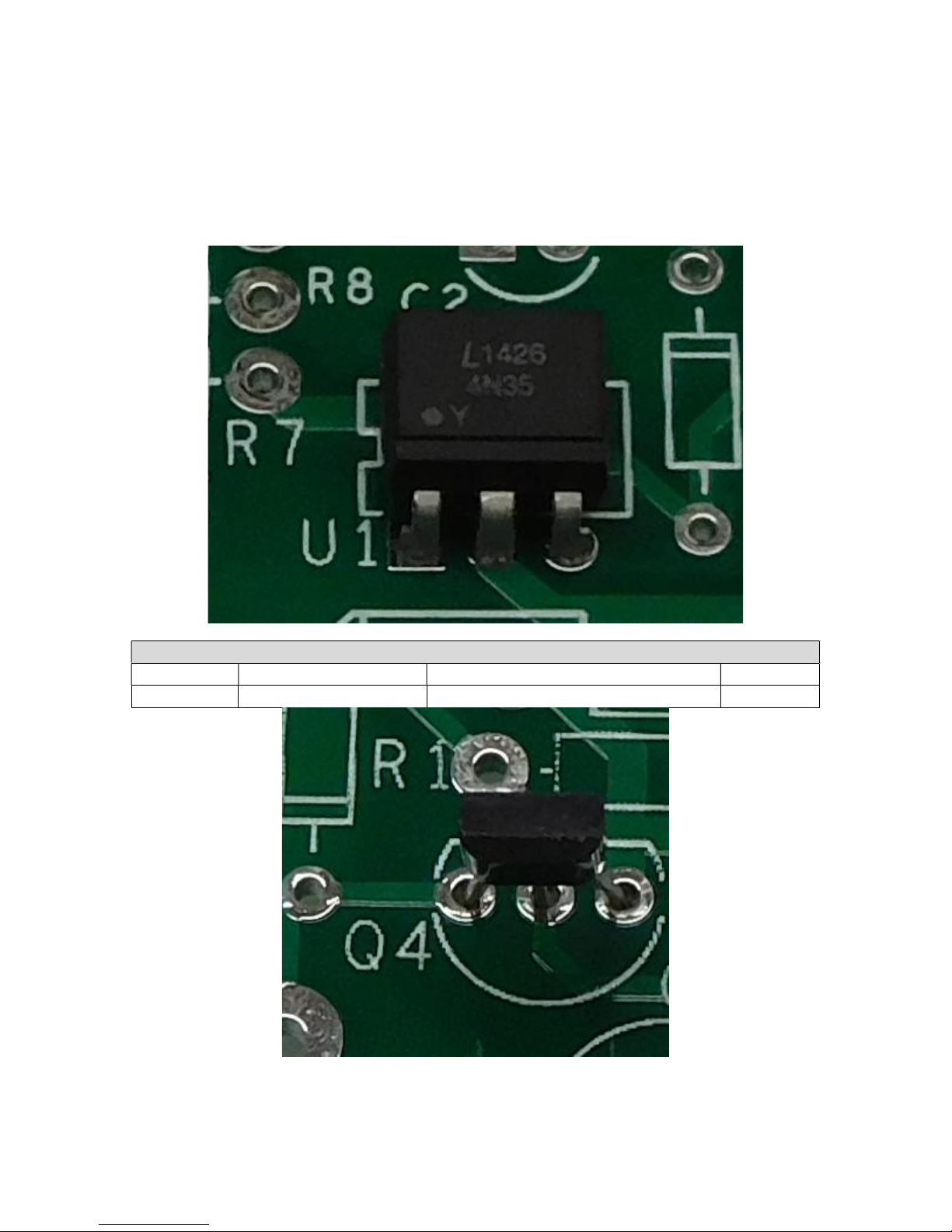
Install the optoisolator
Designation
Type, Package
Rating, Marking, Description
Done? (
) U1 4N35, 6 pin DIP
4N35 opto
-
isolator
The opto isolator comes in a 6-pin DIP (Dual Inline Package). Pin 1 on the PCB is
indicated by the square pad. Pin 1 on the opto-isolator package can be identified by the
dot on the package, refer to Figure 3. Make sure to install the opto with the correct
orientation.
Figure 3-Pin 1 of the opto-isolator is indicated by the dot and the ridge in the package
Opto isolator installation – watch the orientation!
Figure 4-Although more subtle, notice that the Q4 has a square side and a round side
Page 9 of 36
Install the Transistors
keeps the tr
ansistor safe from too much heat during the soldering operation.
Designation
Type
Description
Done? (
) Q1 2N3904
, TO
-92 40
V NPN
bipolar transistor
Q2 2N3904
, TO
-92 40
V NPN
bipolar transistor
Q3 2N3904
, TO
-92 40
V NPN
bipolar transistor
Q4 ZVN211
0A
, TO
-
92 100V N-channel
MOSFET
Orientation of these caps does not matter.
Designation
Description
Done? (
) C3 0.01 uF, 400 Volt film capacitor, box capacitor
the + sign on the silk screen.
Designation
Value
Rating, Marking
Done? (
) C1 22 uF
Electrolytic capacitor,
22
uF 50
V, radial leads
C2 1 uF Electrolytic capacitor,
1 uF
100 V, radial leads
Orient the transistor so its body shape matches the silk-screen outline. Leave the top of
the transistor about ½” off the board! The lead length reduces stress on the body and
Install the Small Non-polar Capacitors
Install the Electrolytic (polarized) Capacitors
Polarized Capacitors (watch polarity and voltage rating). The negative side of the
capacitor is marked with a minus (-) sign. That side of the capacitor installs away from
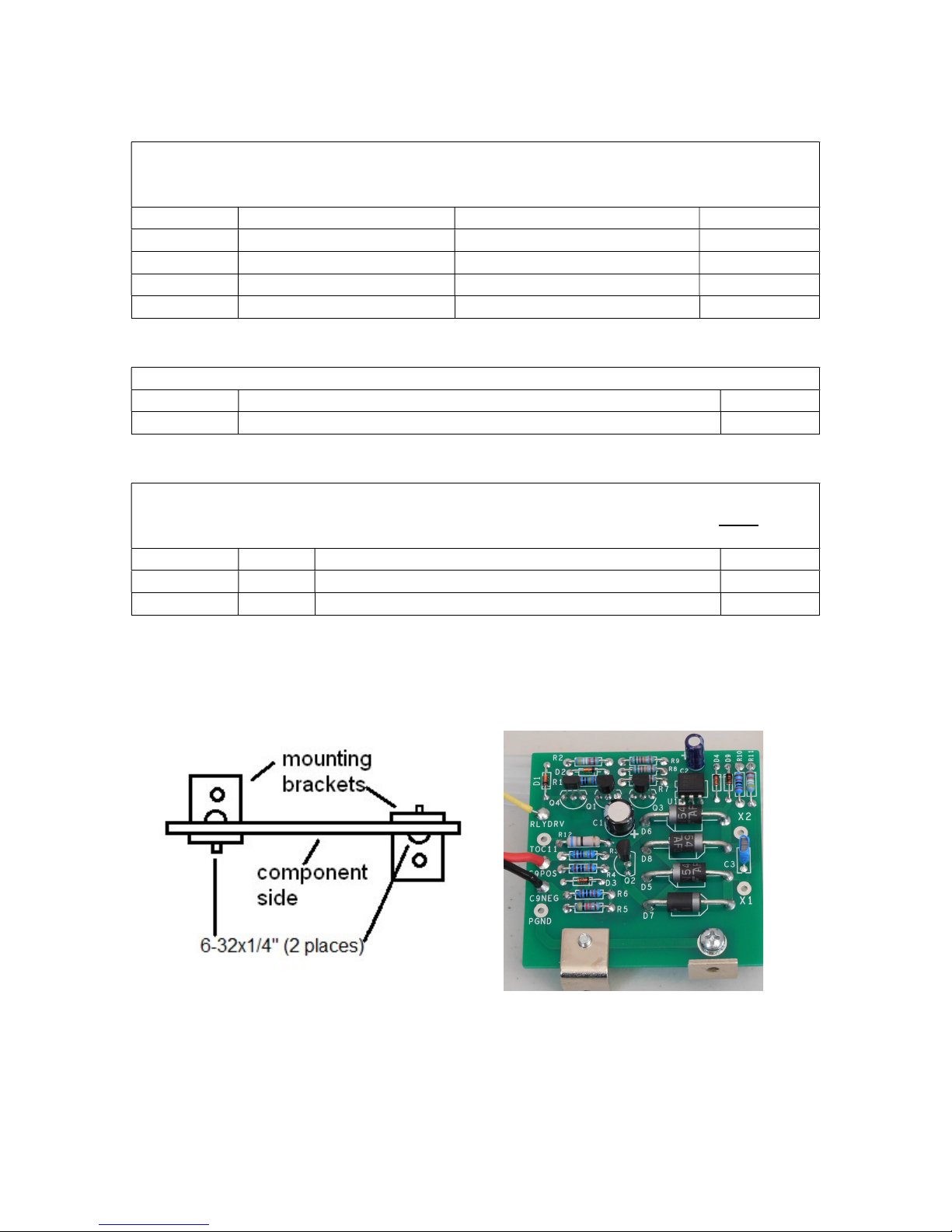
Fasten the Mounting Brackets to the PCB
Using Figure 5 as a guide, fasten the mounting brackets to the PCB using 2 6-32x1/4”
sems screws (they have a built-in lockwasher) into the threaded hole of the mounting
bracket.
Figure 5-Installing the mounting brackets on the power supply PCB
Install the C9 Connection wires
1. Cut a 5” length of the supplied 18 AWG red/black zip cord.
2. Strip ¼” inch of insulation from each of the four ends.
Page 10 of 36
3. Twist and tin the 4 ends.
Unplug t
he power cord before proceeding.
Wait 1 minute for capacitors to discharge.
4. Insert one end of the red wire into the C9POS terminal from the component side
of the board and solder it on the solder side.
5. Insert the accompanying black wire into the C9NEG terminal from the component
side of the board and solder it on the solder side.
Install the RLYDRV wire
Connect an 8.5” length of yellow wire into the RLYDRV eyelet. Insert it from the
component side, and solder it on the solder side. Note that the hole for this wire is kind of
large, so you’ll have the best results if you keep the wire and PCB quite still until the
solder sets.
Check your work
Look over the board to verify that:
1. All components are soldered.
2. No solder bridges are apparent.
3. Polarity of the electrolytic capacitors is correct.
4. Diode polarity is correct.
If everything looks good, you’re ready to install the power supply into your SCA-80 or
Stereo 80.
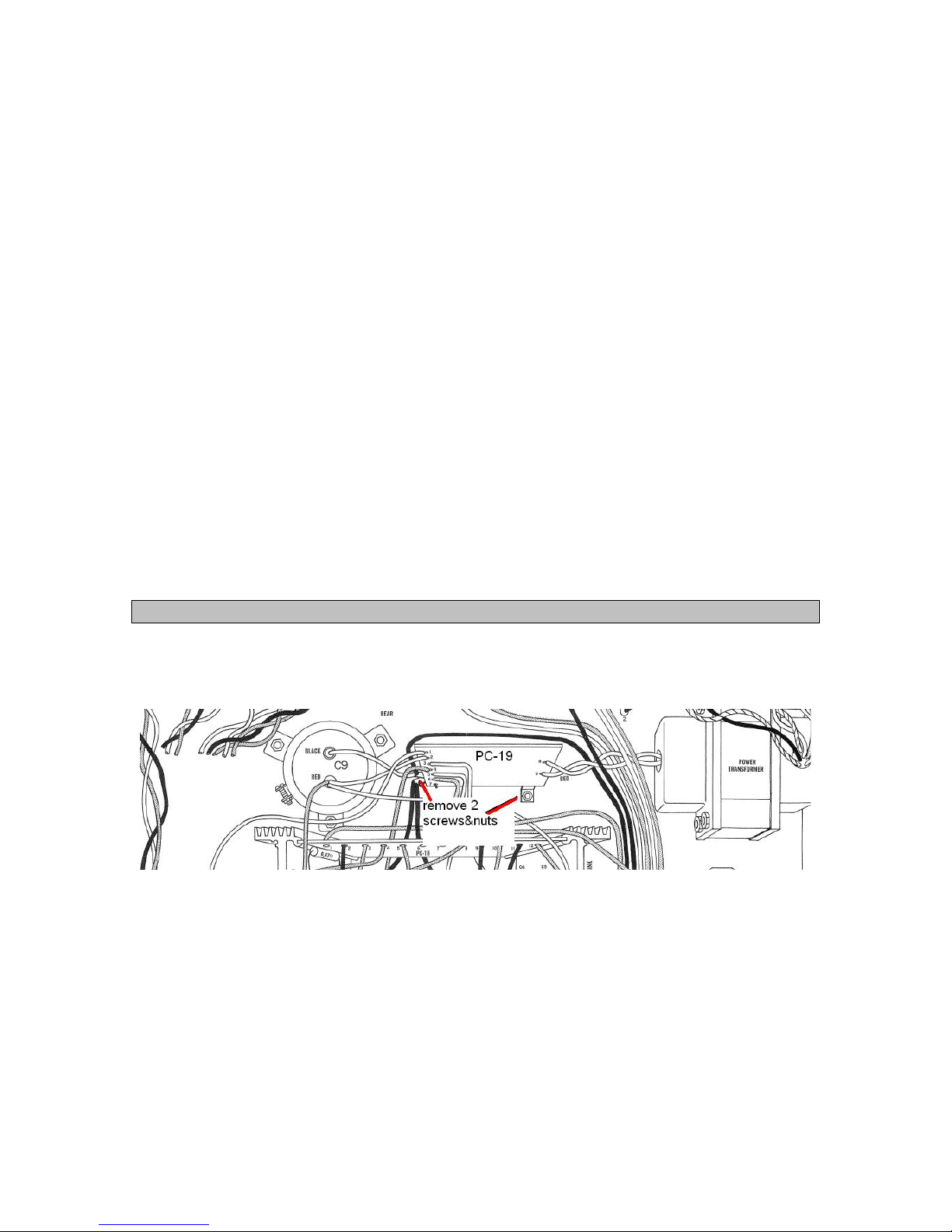
Disconnect the Old Power Supply and Power Amplifier
1. Remove the cover – unscrew and save a total of 5 screws:
a. 2 on the left side
b. 2 on the right side
c. 1 in the center of the top of the back panel.
2. Remove the two sets of screws and nuts that hold the PC-19 brackets to the
bottom of the chassis. That will make it easier to remove the wires as needed in
the next steps.
Page 11 of 36
 Loading...