

Updatemydynaco
Dynaco PAT-5 Preamp
Replacement Power Supply
(PAT5PWR) ASSEMBLY MANUAL
Rev E Hardware
© 2018 AkitikA LLC
All rights reserved
Revision 3p07 September 15, 2018
Page 1 of 18

Table of Contents
Table of Contents ................................................................................................................ 2
Table of Figures .................................................................................................................. 2
Section 1: About This Manual ............................................................................................ 3
Who Should Attempt this Project? ................................................................................. 3
Tools you’ll need ............................................................................................................ 3
Helpful Tools .................................................................................................................. 3
Project Overview ............................................................................................................ 3
Important Safety Notes ................................................................................................... 4
About Components ......................................................................................................... 4
Recommended Solder ..................................................................................................... 4
Warranty ......................................................................................................................... 4
Section 2: Kit Building Hints .............................................................................................. 5
Section 3: Building the Power Supply ................................................................................ 6
Component Order............................................................................................................ 7
Install the Resistors ......................................................................................................... 7
Install the diodes ............................................................................................................. 7
Install R14 ....................................................................................................................... 8
Install the TO-220 Regulators, Power Transistors and Heatsinks .................................. 8
Assembly Hint ............................................................................................................ 9
Install the Small Non-polar Capacitors ......................................................................... 10
Install Shunt Regulator and Small Transistor ............................................................... 10
Install the Electrolytic (polarized) Capacitors .............................................................. 10
Check your work ........................................................................................................... 11
Checking the preamp and old power supply ..................................................................... 11
If your voltages were out of tolerance ...................................................................... 12
Removing the Old Power Supply ................................................................................. 13
Installing the New Power Supply ................................................................................. 15
Testing the power supply in place ............................................................................ 16
Final Re-Assembly.................................................................................................... 17
About the Design .......................................................................................................... 17
Table of Figures
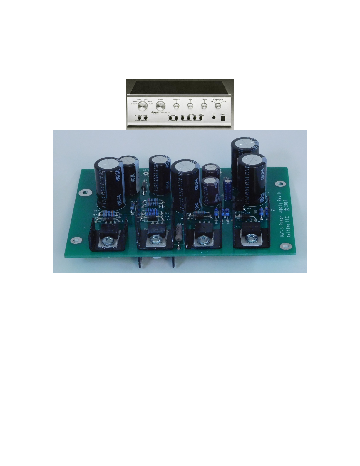
Figure 1-Assembled PAT-5 Power Supply. Note that U2, U3, and Q2 get tall heatsinks . 5
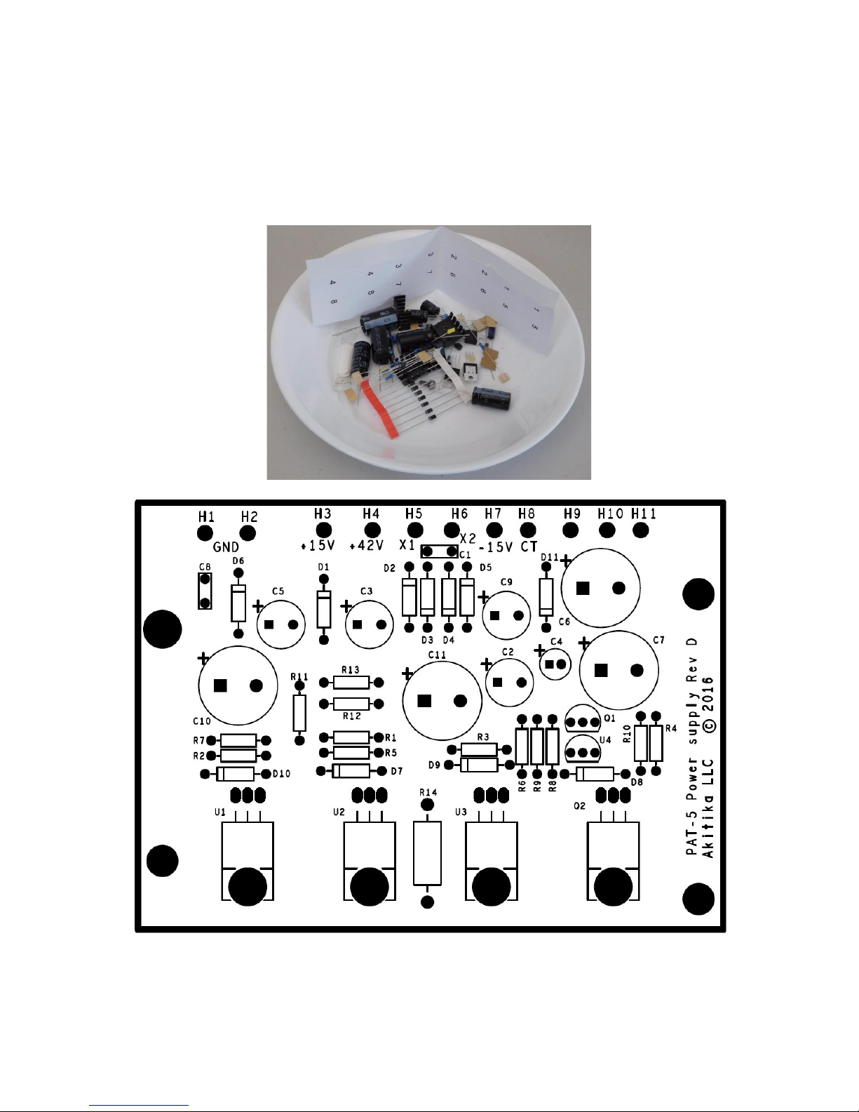
Figure 2-Empty the power supply components into a soup bowl ....................................... 6
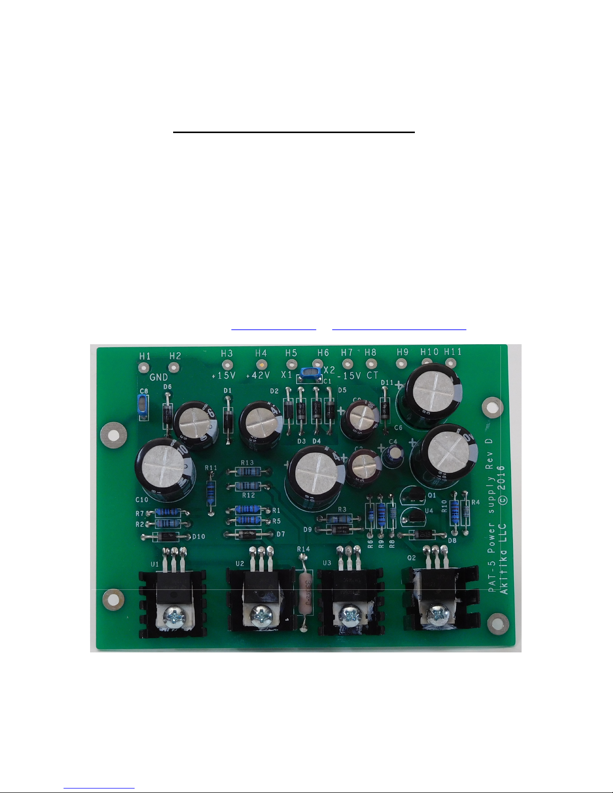
Figure 3-Silk screen shows power supply component locations ........................................ 6
Figure 4-Regulator and Heat Sink Assembly Detail........................................................... 8
Figure 5-Applying thermal compound ................................................................................ 9
Figure 6-Heatsink Installation............................................................................................. 9
Figure 7-Line up the bottom heatsink to not touch the nearby trace ................................ 10
Figure 8-Remove hardware that holds power supply bracket to chassis floor ................. 13
Figure 9-Remove these 2 screws and 2 screws on the opposite side ................................ 14
Figure 10-Remove the screws and nuts that hold the zig-zag shield to back and front of
chassis ............................................................................................................................... 14
Figure 11-Mount new PCB to shield and mounting brackets ........................................... 15
Page 2 of 18

Section 1: About This Manual
This manual gives the information needed to build and install the upgraded power supply
for Dynaco’s PAT-5 Preamp. This manual covers the assembly of Rev E hardware. Rev
E hardware.
The Rev E version can support up to 100 mA load current, nearly twice of what earlier
versions can support. This is being done on speculation to prepare for some future
projects.
Who Should Attempt this Project?
You can build this kit if you can:
1. Solder (using normal rosin core solder and a soldering iron).
2. Use simple hand tools like screwdrivers, wire cutters, and pliers.
3. Read and follow directions.
It helps if you:
1. know a bit about electronics, or
2. have a friend who knows a bit about electronics
3. can get to YouTube to watch a few helpful videos about the assembly process
(none are posted as of this version of the manual).
Tools you’ll need
You’ll need the following tools:
1. Phillips screwdriver (#1 and #2), regular screw-drivers.
2. Pliers or nut drivers suitable for #4 and #6 hardware
3. needle nose pliers (helpful, but not strictly necessary)
4. pencil type soldering iron of 25 to 50 Watts (no huge honking soldering guns or
blowtorches)
5. wire cutters and strippers
6. multi-meter to measure power supply voltages and confirm resistor values
(strongly recommended)!
Helpful Tools
These tools aren’t strictly necessary, but make building the kit easier.
1. magnifying glass, if you’re over 42!
2. lead bending jig to form axial component leads to the correct span for insertion in
the PCB.
Project Overview
The project consists of the following steps:
1. Building the circuit board.
2. Removing the old power supply
3. Installing and testing the new power supply
4. Completing re-assembly of the preamp.
Page 3 of 18

Important Safety Notes
notification.
By purchasing, using, or assembling this kit, you have agreed to hold Akitika LLC
harmless for any injuries you may receive in its assembly and/or use. To prevent injuries:
Wear safety glasses when soldering or clipping wires to prevent eye injuries.
Always unplug the power before working on the amplifier.
Large capacitors hold lots of energy for a long time. Before you put your hands
into the amplifier:
o Pull the AC plug!
o Wait 2 full minutes for the capacitors to discharge!
Remove jewelry and rings from your hands and wrists, or anything that might
dangle into the amplifier.
If working one the equipment with the power on, keep one hand in your pocket,
especially if you’re near the power supply or power supply wires. This can
prevent serious shocks.
Build with a buddy nearby. If you’ve ignored all the previous advice, they can
dial 911 or get you to the hospital.
Read and understand the safety manuals of all the tools you use.
About Components
We reserve the right to make design/or component changes at any time without prior
Recommended Solder
The kit must be assembled with 60/40 Rosin Core solder. The recommended diameter is
0.032 inches. Among many such sources of solder, I have used Radio Shack part number
64-009. It contains 8 oz. of solder, which is much more than you’ll need to assemble this
kit.
Warranty
With the exception of fuses, Akitika LLC will replace for free any parts of a correctly
assembled product that fails within one year of the date of purchase when the equipment
has been used in home stereo applications. It is the responsibility of the kit builder to
install the replacement part(s). This warranty applies to the original purchaser only. It
does not apply to units that have been physically or electrically abused, modified without
prior factory authorization, or assembled with other than 60/40 Rosin Core solder.
Akitika LLC’s liability shall in no event exceed the cost paid to Akitika LLC for the kit.
Page 4 of 18
Section 2: Kit Building Hints
Yes, I know you want to ignore this section, and jump right into building the kit.
However, please take a minute and read the advice of this section. I’ve condensed it into
bullets so that even you guys who are in a hurry can benefit.
Stop any time you’re feeling confused, tired, or anxious. Taking breaks at those
strategic times will keep the build enjoyable and greatly enhance your chances of
first-time success.
A soup bowl is your friend. Before you build a board, carefully empty the parts
into a broad, flat, light colored soup bowl. That makes it easy to find the parts,
and keeps them from getting lost.
A digital ohm-meter is an easy way to make sure that you’ve picked the right
resistor. It’s a great cross-check on the resistor color code. Measure twice and
solder once!
A lead-bending jig can make for quicker, neater assembly. It’s certainly not
necessary.
Is something in this manual confusing? Does something look wrong? Send your
questions by email to dan@akitika.com or dan@updatemydynaco.com. You’ll
help yourself and everyone who builds the kit.
Figure 1-Assembled PAT-5 Power Supply. Note that U2, U3, and Q2 get tall heatsinks
Page 5 of 18
Section 3: Building the Power Supply
This section details the process of building the power supply circuit board. Begin by
carefully emptying the contents of the parts envelope into a broad soup bowl, as shown
below. In general, you’ll start with the components that lay closest to the board, working
your way towards the taller components.
Figure 2-Empty the power supply components into a soup bowl
Figure 3-Silk screen shows power supply component locations
Page 6 of 18
 Loading...