

Dynabrade Dynangle II 14300, Dynangle II 14302, Dynangle II 14303, Dynangle II 14306 Important Operating, Maintenance And Safety Instructions
Page 1
Models:
14300 – Standard Duty
14302 – Heavy-duty “Dual Motor”
14303 – Heavy-duty “Dual Motor” w/ Platen
14306 – Heavy-duty “Dual Motor” w/ Platen (2" x 45" belts)
Machine and Motor Parts
Parts Page Reorder No. PD01•93
Effective October, 2001
Supercedes PD92•04
Dynangle
®
II
Always operate, inspect and maintain this tool in accordance with the Safety Code for portable air tools
(ANSI B186.1) and any other applicable safety codes and regulations. Please refer to Dynabrade’s
Warning/Safety Operating Instructions for more complete safety information.
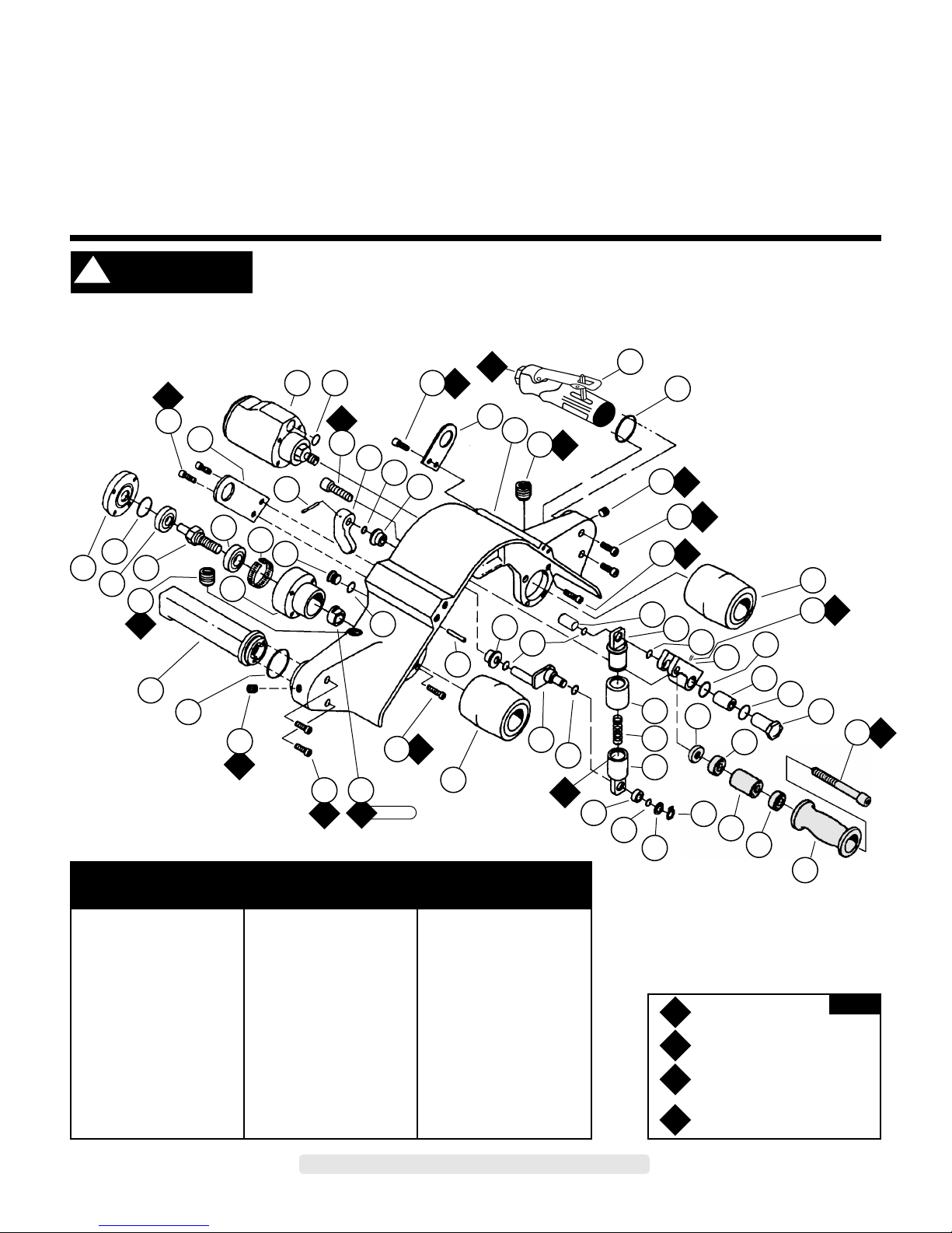
Machine Assembly
Model 14300 — for 2" x 34" belts / Standard duty — for strap polishing
*See page 5 for 07167 Throttle Valve and 07102 Motor Assemblies.
Shaded area represents 14334 Tension Wheel Assembly.
Index Key
No. Part # Description
1 07167 Throttle Valve Assy.*
2 14064 O-Ring
3 95562 Plug (2)
4 95720 Screw (2)
5 95221 Screw (4)
6 01794 Drive Wheel (2)
7 14353 Bushing
8 14317 Retainer
9 95288 O-Ring (6)
10 14316 Idle Arm
11 95526 O-Ring (2)
12 95555 Bearing
13 14343 Step Nut
14 95565 Screw
15 14344 Tension Idler
16 95398 Bearing (2)
17 14346 Spacer
18 14347 Spacer
19 95558 Retaining Ring
20 95557 Washer
21 95572 Bushing
22 14318 Retainer
23 95556 Spring
24 14319 Cover
25 14324 Cam Assembly
26 95560 Bearing (2)
27 95333 Pin
28 95564 Screw (4)
29 14330 Nut
30 95720 Screw (2)
31 14064 O-Ring
32 14332 Dead Handle Assy.
33 95561 Plug (2)
34 14329 Shaft
35 01266 Bearing
36 95584 O-Ring
37 14328 Cover
38 14327 Housing
39 01025 O-Ring (2)
40 14348 Plug
41 95583 Ring
42 02552 Bearing
43 95536 Screw (4)
44 14333 Bracket (2)
45 95164 Pin
46 07102 Motor
47 95559 Screw
48 14331 Lever
49 14320 Housing
50 95952 Set Screw
1*
44
34
39
40
38
41
42
44
45
26
37
48
946
36
37
35
2
6
7
8
9
10
11
12
11
13
15
16
17
24
23
22
20
9
21
6
26
9
25
9
27
31
32
19
16
18
A
2
O
1
A
8
A
2
A
2
A
2
A
2
G
2
A
2
A
2
A
8
A
8
A
2
A
2
A
8
43
33
4
3
5
14
28
30
3
33
43
47
49
23 N•m
T
29
50
O
G
A
T
Adhesive: A
2
= Loctite #271
A
8
= Loctite #567
Torque: N•m x 8.85 = In - lbs.
Oil: O
1
=
Air Lube
Grease: G
2
=
Loctite #771
KEY
!
WARNING
Page 2
A
2
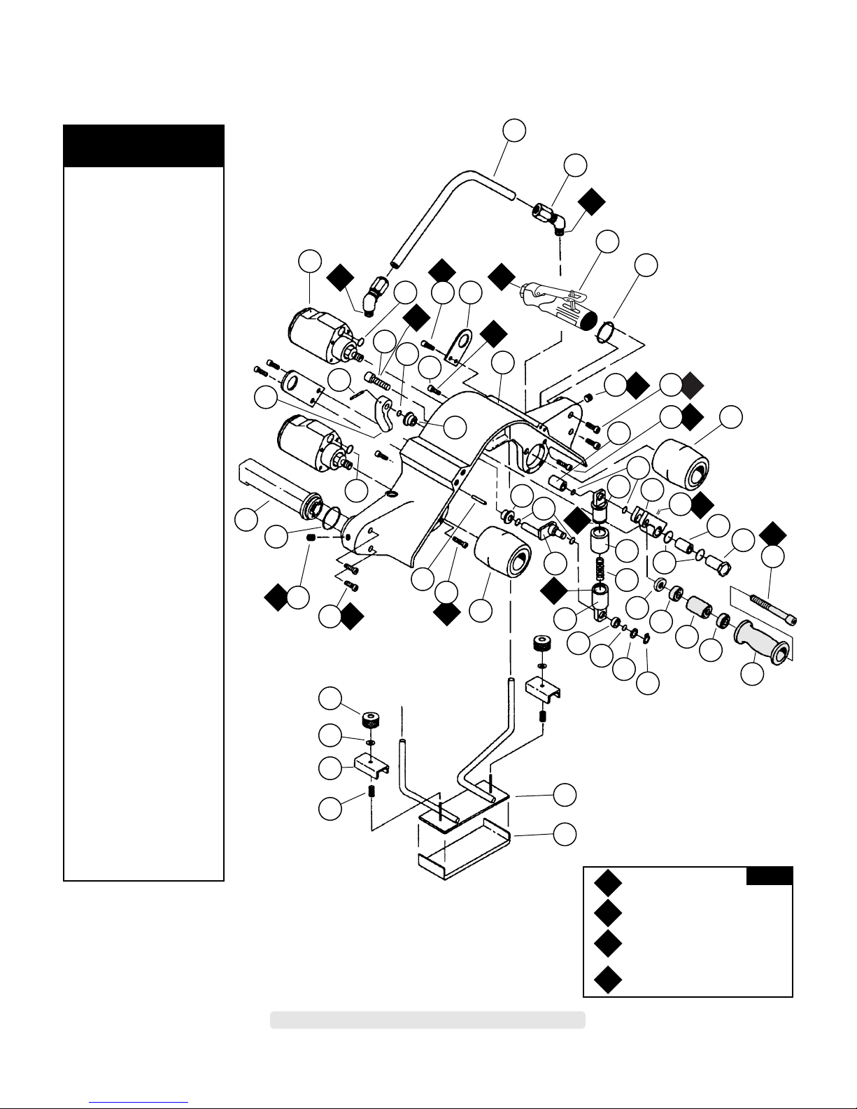
Machine Assembly
Model 14302 — for 2" x 34" belts / Heavy-duty — for strap polishing
Model 14303 — for 2" x 34" belts / Heavy-duty — with 14336 Platen Assembly
2
*See page 5 for 07167 Throttle Valve and 07102 Motor Assemblies.
1 14335 Air Line
2 95566 Fitting (2)
3 07167 Throttle Valve Assy.*
4 14064 O-Ring (2)
5 95562 Plug (2)
6 95720 Screw (4)
7 95221 Screw (8)
8 01794 Drive Wheel (2)
9 95288 O-Ring (7)
10 14316 Idler Arm
11 95526 O-Ring (2)
12 95555 Bearing
13 14343 Step Nut
14 95565 Screw
15 14344 Tension Idler
16 95398 Bearing (2)
17 14346 Spacer
18 14347 Spacer
19 95556 Spring
20 14319 Cover
21 14317 Retainer
22 95558 Retainer Ring
23 95557 Washer
24 95572 Bushing
25 14318 Retainer
26 14337 Mount
27 14341 Platen Pad
28 95570 Spring (2)
29 14338 Clamp (2)
30 95563 Washer (2)
31 14342 Knob (2)
32 14324 Cam Assembly
33 95560 Bearing (2)
34 95333 Pin
35 14332 Dead Handle Assy.
36 14331 Lever
37 95164 Pin
38 07102 Motor (2)
39 95559 Screw
40 01025 O-Ring
41 95150 Screw (2)
42 95536 Screw (4)
43 14333 Bracket (2)
44 14320 Housing
45 14353 Bushing
46 95952 Set Screw
Index Key
No. Part # Description
3*
1
2
15
16
17
16
18
19
22
23
9
24
27
31
30
29
28
26
25
32
8
34
4
35
43
44
41
39
37
33
40
36
9
9
38
33
9
20
21
45
11
9
13
10
8
4
A
8
A
2
G
2
G
2
A
2
O
1
A
2
G
2
A
2
A
2
A
8
A
8
A
8
A
2
A
2
5
6
7
14
7
6
5
42
O
G
A
T
Adhesive: A
2
= Loctite #271
A
8
= Loctite #567
Torque: N•m x 8.85 = In - lbs.
Oil: O
1
=
Air Lube
Grease: G
2
= Loctite #771
KEY
12
46
Shaded area represents 14334 Tension Wheel Assembly.
Page 3

Important Operating, Maintenance and Safety Instructions
Carefully read all instructions before operating or servicing any Dynabrade®Abrasive Power Tool.
Warning: Hand, wrist and arm injury may result from repetitive work motion and overexposure to vibration.
Important: All Dynabrade Rotary Vane air tools must be used with a Filter-Regulator-Lubricator to maintain all warranties.
Operating Instructions:
Warning: Eye, face, respiratory, sound and body protection must be worn while operating power tools. Failure to do so may result in serious injury or death.
Follow safety procedures posted in workplace.
1. With power source disconnected from tool, securely fasten abrasive / accessory on tool.
2. Install air fitting into inlet bushing of tool. Important: Secure inlet bushing of tool with a wrench before attempting to install the air fitting to avoid
damaging valve body housing.
3. Connect power source to tool. Be careful not to depress throttle lever in the process.
4. Check tool speed with tachometer. If tool is operating at a higher speed than the RPM marked on the tool or operating improperly, the tool should be
serviced to correct the cause before use.
Maintenance Instructions:
1. Check tool speed regularly with a tachometer. If tool is operating at a higher speed than the RPM marked on the tool, the tool should be serviced to
correct the cause before use.
2. Some silencers on air tools may clog with use. Clean and replace as required.
3. All Dynabrade Rotary Vane air motors should be lubricated. Dynabrade recommends one drop of air lube per minute for each 10 SCFM (example: if the
tool specification states 40 SCFM, set the drip rate of your filter-lubricator at 4 drops per minute).
Dynabrade Air Lube (P/N 95842: 1 pt. 473 ml.) is recommended.
4. An Air Line Filter-Regulator-Lubricator must be used with this air tool to maintain all warranties. Dynabrade recommends the following: 11411 Air Line
Filter-Regulator-Lubricator — Provides accurate air pressure regulation, two-stage filtration of water contaminants and micro-mist lubrication of pneumatic
components. Operates 55 SCFM @ 100 PSIG has 1/2" NPT female ports.
5. Use only genuine Dynabrade replacement parts. To reorder replacement parts,please specify the Model #, Serial # and RPM of your machine.
6. A Motor Tune-Up Kit (P/N 96011) is available which includes assorted parts to help maintain motor in peek operating condition.
7. Mineral spirits are recommended when cleaning the tool and parts. Do not clean tool or parts with any solvents or oils containing acids, esters, keytones,
chlorinated hydrocarbons or nitro carbons.
3
One Year Warranty
Following the reasonable assumption that any inherent defect which might prevail in a product will become apparent to the user within one year from the date
of purchase, all equipment of our manufacture is warranted against defects in workmanship and materials under normal use and service. We shall repair or
replace at our factory, any equipment or part thereof which shall, within one year after delivery to the original purchaser, indicate upon our examination to
have been defective. Our obligation is contingent upon proper use of Dynabrade tools in accordance with factory recommendations, instructions and safety
practices. It shall not apply to equipment which has been subject to misuse, negligence, accident or tampering in any way so as to affect its normal
performance. Normally wearable parts such as bearings, contact wheels, rotor blades, etc., are not covered under this warranty.
• Important: User of tool is responsible for following accepted safety codes such as those published by the American National Standards Institute (ANSI).
• Operate machine for one minute before application to workpiece to determine if machine is working properly and safely before work begins.
• Always disconnect power supply before changing abrasive/accessory or making machine adjustments.
• Inspect abrasives/accessories for damage or defects prior to installation on tools.
• Please refer to Dynabrade’s Warning/Safety Operating Instructions Tag (Reorder No. 95903) for more complete safety information.
• Warning: Hand, wrist and arm injury may result from repetitive work, motion and overexposure to vibration.
Notice
All Dynabrade motors use the highest quality parts and metals available and are machined to exacting tolerances. The failure of quality pneumatic motors can
most often be traced to an unclean air supply or the lack of lubrication. Air pressure easily forces dirt or water contained in the air supply into motor bearings
causing early failure. It often scores the cylinder walls and the rotor blades resulting in limited efficiency and power. Our warranty obligation is contingent upon
proper use of our tools and cannot apply to equipment which has been subjected to misuse such as unclean air, wet air or a lack of lubrication during the use
of this tool.
Safety Instructions:
Products offered by Dynabrade should not be converted or otherwise altered
from original design without expressed written consent from Dynabrade, Inc.
Model Motor Motor Sound Abrasive Belt Size Maximum Air Flow Max. SFPM Weight Length Height
Number HP (W) RPM Level Inch (mm) CFM/SCFM (LPM) (SMPM) Pound (kg) Inch (mm) Inch (mm)
14300 1.2 (895) 13,000 85 dB(A) 2 (51) W x 34 (864) L 7/53 (1,501) 8,500 (2,582) 15.1 (6.9) 18-7/8 (480) 8-1/2 (216)
14300 2.4 (1,790) 13,000 85 dB(A) 2 (51) W x 34 (864) L 15/106 (3,002) 8,500 (2,582) 17.4 (7.9) 18-7/8 (480) 9-9/16 (243)
14300 2.4 (1,790) 13,000 85 dB(A) 2 (51) W x 34 (864) L 15/106 (3,002) 8,500 (2,582) 18.7 (8.5) 18-7/8 (480) 9-9/16 (243)
14300 2.4 (1,790) 13,000 90 dB(A) 2 (51) W x 45 (1,143) L 15/106 (3,002) 8,500 (2,582) 19.2 (8.7) 22-7/8 (581) 9-1/2 (241)
Additional Specifications: Air Inlet Thread 1/2" NPT • Hose Size 1/2" (15 mm) • Air Pressure 90 PSIG (6.2 Bars)
Page 4

4
Machine Assembly
Model 14306 — for 2" x 45" belts / Heavy-duty — with 14339 Platen Assembly
*See page 5 for 07167 Throttle Valve and 07102 Motor Assemblies.
Shaded part numbers represent 14334 Tension Wheel Assembly.
1 14345 Air Line
2 95566 Fitting (2)
3 07167 Throttle Valve Assy.*
4 14064 O-Ring (2)
5 95562 Plug (2)
6 95720 Screw (4)
7 95221 Screw (8)
8 01794 Drive Wheel (2)
9 95288 O-Ring (7)
10 14316 Idler Arm
11 95526 O-Ring (2)
12 95555 Bearing
13 14343 Step Nut
14 14347 Spacer
15 95398 Bearing (2)
16 14346 Spacer
17 95565 Screw
18 14344 Tension Idler
19 95558 Retaining Ring
20 95557 Washer
21 95572 Bushing
22 14318 Retainer
23 95581 Spring
24 14319 Cover
25 14324 Cam Assembly
26 14317 Retainer
27 95560 Bearing (2)
28 95333 Pin
29 14351 Mount
30 14341 Platen Pad
31 95570 Spring (2)
32 14338 Clamp (2)
33 95563 Washer (2)
34 14342 Knob (2)
35 07102 Motor (2)
36 14332 Dead Handle Assy.
37 14331 Lever
38 95536 Screw (4)
39 95164 Pin
40 95559 Screw
41 14333 Bracket (2)
42 01025 O-Ring
43 95150 Screw (2)
44 14353 Bushing
45 95952 Set Screw
Index Key
No. Part # Description
1
2
3*
4
8
9
10
18
19
15
16
15
14
9
20
21
29
30
22
2728
35
9
37
28
44
39
35
9
4
36
41
42
26
9
24
25
23
31
32
33
34
11
11
12
13
A
8
G
2
A
2
A
2
A
8
O
1
A
8
A
2
A
2
A
2
A
2
A
2
A
2
A
8
G
2
43
40
38
5
7
8
17
7
6
5
6
45
O
G
A
T
Adhesive: A
2
= Loctite #271
A
8
= Loctite #567
Torque: N•m x 8.85 = In - lbs.
Oil: O
1
= Air Lube
Grease: G
2
= Loctite #771
KEY
Page 5

5
Note: On Models 14302, 14303, and 14306 the 07167 Throttle Valve Assembly can be mounted on either side of the tool for right or left hand comfort.
07167 Throttle Valve Assembly
Heavy-Duty Air Motor 07102 - Dynangle
®
II
1 14064 O-Ring
2 07086 Adapter
3 07136 Handle Grip
4 02658 Packing
5 02631 Nut
6 02626 Adjustment Bushing
7 01746 O-Ring
8 07141 Valve Body Assembly
(Incl. 07142 Bushing)
9 07142 Bushing
10 01089 Lever
11 01697 Inlet Bushing
12 01017 Pin
13 07168 Valve Stem Assembly
14 07145 Spring
15 07146 Packing
16 07147 Plug
17 95720 Screw (2)
Index Key
No. Part # Description
1 01794 Drive Wheel
2 02553 Adapter
3 95584 O-Ring
4 01674 Silencer
5 07153 Air Control Ring
6 01036 Bearing
7 01277 Shim Pack (3/Pkg.)
8 07119 Bearing Plate
9 07107 Blades (5/Pkg.)
10 07103 Rotor
11 01673 Guide Pin
12 07118 Cylinder
13 01775 Guide Pin
14 07114 Bearing Plate
15 01007 Bearing
16 07132 Housing
17 07129 Gasket
18 07122 Housing Cap
19 01791 Washer (4)
20 01790 Screw (4)
Index Key
No. Part # Description
6431 5
151413121110
16 17 18
2
17
3 4 7
13
12
14
15
10
9
1
19
7 8
O
1
A
6
A
8
O
1
A
2
9
5
6
8
23 N•m
T
8 N•m
T
45 N•m
T
17 N•m
T
50 N•m
T
45 N•m
T
2
20
11
16
A
2
A
8
O
G
A
T
Adhesive: A2= Loctite #271
A
6
= Loctite #380
A
8
= Loctite #567
Torque: N•m x 8.85 = In - lbs.
Oil: O
1
=
Air Lube
Grease: G
2
= Loctite #771
KEY
Page 6

Disassembly/Assembly Instructions
Important: Manufacturer’s warranty is void if tool is disassembled before warranty expires.
A Motor Tune-Up Kit is available (P/N 96011) to help maintain motor in peek operating condition.
Tool Disassembly:
1. Disconnect tool from power source.
2. Remove any abrasive belt from machine.
3. Roll 07136 Handle Grip away from 07086 Adapter to expose wrench flats.
4. Remove 07086 Adapter from housing (right hand thread). Separate 07167 Throttle Valve Assembly from machine assembly.
5. Insert 01697 Inlet Bushing securely into vise.
6. Remove 02631 Nut by using a 32 mm wrench.
7. Remove 01794 Drive Wheel with a 19 mm wrench.
8. Remove 95221 Screws (4) and disconnect 07102 Motor Assembly from machine housing.
9. Place 07102 Motor Assembly housing in soft jaw vise. Important: Be careful not to over tighten vise to prevent damage.
10. Remove 01790 Screws (4) and 01791 Washers (4) from 07122 Housing Cap. Remove housing cap and 07129 Gasket.
Motor Disassembly:
1. Fasten a 2 in. bearing separator around the rear portion of the 07118 Cylinder and using a #2 arbor press (P/N 96232 available) place the separator on
the table of the arbor press so that the motor spindle points toward the floor.
2. Use a 3/16 in. Dia. flat nose drive punch as a press tool and push against the rear shaft of the rotor to remove rear bearing/plate assembly.
3. Hold the body of the 07103 Rotor in a soft (aluminum or bronze) jaw vise and remove 02553 Adapter.
4. Remove 07119 Front Bearing Plate, 01036 Front Bearing from 07103 Rotor.
Note: Bearing, front bearing plate are a slip fit onto rotor.
5. Push 01036 Bearing Plate and remove shims from front bearing plate.
Motor Disassembly Complete.
Motor Assembly:
Important: Be certain all parts are cleaned and in good repair before assembling.
1. Place 07103 Rotor in soft (aluminum or bronze) jaw vise with threaded spindle pointing upwards.
2. Place .002" shim into front bearing plate as initial spacing and slip 01036 Bearing into plate. Note: 01277 Shim Pack contains .001" and .003" shims.
3. Install bearing/bearing plate assembly onto rotor.
4. Install 02553 Adapter onto assembly.
5. Tighten 02553 Adapter onto rotor, torque 23 N•m/200 in. - lbs.
6. Check clearance between rotor and bearing plate by using a .001" feeler gauge. Clearance should be at .001" to .0015". Adjust clearance by repeating
steps 1-5 with different shims if necessary.
7. Once proper rotor/gap clearance is achieved, install lubricated 07107 Blades (5) into rotor slots. Dynabrade Air Lube P/N 95842 (or equivalent) is
recommended for lubrication before installation in rotor slots.
8. Install cylinder over rotor.
9. Press the 01007 Rear Bearing into 07114 Rear Bearing Plate. Press bearing/bearing plate assembly onto rotor. Be sure that pin and air inlet line-up
with pin hole and air inlet in cylinder.
10. Place 95584 O-Ring 01674 Silencer and 07153 Exhaust Ring into housing.
11. Slide motor assembly into motor housing.
12. Install 07129 Gasket and 07122 Housing Cap with 01790 Screws (4) and 01791 Washers (4), tighten screws to 9 N•m/80 in. - lbs.
13. Motor adjustment can now be checked. With motor housing still mounted in vise, pull end of rotor and twist (10-15 lbs. force), rotor should turn
freely without drag. If drag or rub is felt, then increase preload or remove shim. Also, push end of rotor and twist (10-15 lbs. force), rotor should
turn freely without drag. If drag or rub is felt, then deload or add a shim.
14. Install 95221 Screws (4) to connect 07102 Motor Assembly onto machine housing.
15. Apply 2 drops of #271 Loctite
®
(or equivalent) to threads of 02626 Adjustment Bushing before tightening.
16. Slip 02626 Adjustment Bushing through 02631 Nut and 02658 Packing, and secure into 07886 Adapter.
17. Apply Loctite
®
#271 (or equivalent) and tighten 02626 Adjustment Bushing into housing torque to 50 N•m/450 in. - lbs.
18. Apply Loctite
®
#567 (or equivalent) to threads of 07141 Valve Body, and fasten 02631 Nut and 01746 O-Ring onto valve body. Swivel 07141 Valve Body
to desired throttle lever position.
19. Tighten 02631 Nut to 45 N•m/400 in. - lbs. Roll 07136 Grip back into place.
Tool Assembly Complete. Please allow 30 minutes for adhesives to cure before operating tool.
Important: Motor should now be tested for proper operation at 90 PSIG. If motor does not operate properly or operates at a higher RPM than marked on the
tool, the tool should be serviced to correct the cause before use. Before operating, place 2-3 drops of Dynabrade Air Lube (P/N 95842) directly into air inlet
with throttle lever depressed. Operate tool for thirty seconds to determine if tool is operating properly and to allow lubricating oils to properly penetrate motor.
Loctite®is a registered trademark of Loctite Corp.
6
Page 7

7
Optional Accessories
Abrasive Belts
Coated Aluminum Oxide
Dynaswivel
®
Swivels 360° at two locations which
allows an air hose to drop straight to
the floor, no matter how the tool is held.
• 95462 1/2" NPT
96011 Motor Tune-Up Kit:
• Includes assorted parts to help maintain
and repair motor.
• Two kits are required.
Dynabrade Air Lube
• Formulated for pneumatic equipment.
• Absorbs up to 10% of its weight in water.
• Prevents rust and formation of sludge.
• Keeps pneumatic tools operating longer
with greater power and less down time.
95842: 1 pt. (473 ml)
95843: 1 gal. (3.8 L)
Wrenches
95303 – 1/4" Hex Wrench 95304 – 24 mm Open-End
96079 – 32 mm Open-End
Belt Abrasive Grit
Width 40 60 80 100 120 180 220 320 500
1" 90284 90285 90286 90148 90287 90288 90289 90290 90291
2" 90376 90377 90378 90379 90380 ––––
2" 90348 90349 90350 90351 90352 ––––
18" Long
34" Long
45" Long
1" Belts: Unit = 200 Belts. 2" Belts: Unit = 50 Belts
Non-Woven Nylon
Grade/Belt Color
Belt Super Fine/Grey Very Fine/Blue Medium/Maroon Course/Brown
Width Grit Range 320-600 Grit Range 220-320 Grit Range 150-180 Grit Range 80-150
1" 90162 90259 90295 90300
2" – 90371 90373 90374
18" Long
34" Long
1" and 2" Belts: Unit = 10 Belts.
Page 8

DYNABRADE
®
DYNABRADE, INC., 8989 Sheridan Drive • Clarence, NY 14031-1490 • Phone: (716) 631-0100 • Fax: 716-631-2073 • International Fax: 716-631-2524
DYNABRADE EUROPE S.àr.l., Zone Artisanale • L-5485 Wormeldange—Haut, Luxembourg • Telephone: 352 76 84 94 1 • Fax: 352 76 84 95 1
© DYNABRADE, INC., 2001 PRINTED IN USA
Visit Our Web Site: www.dynabrade.com Email: Customer.Service@Dynabrade.com
Toll Free (U.S.A.) 1-800-826-7333
Toll Free (Can.) 1-800-344-1488
 Loading...