

Page 1
Always operate, inspect and maintain this tool in accordance with the Safety Code for portable air tools (ANSI B186.1) and any other applicable safety codes
and regulations. Please refer to Dynabrade’s Warning/Safety Operating Instructions for more complete safety information.
Models:
57902 — 13,000 RPM, Wet Dynafine
®
Wet Dynafine®Sander
Parts Page Reorder No. PD03•31
Effective September, 2003
Supersedes PD02•20T
Loctite: A1= Loctite #609
A
2
= Loctite #271
A
8
= Loctite #567
Torque: N•m x 8.85 = In. - lbs.
KEY
A
T
O
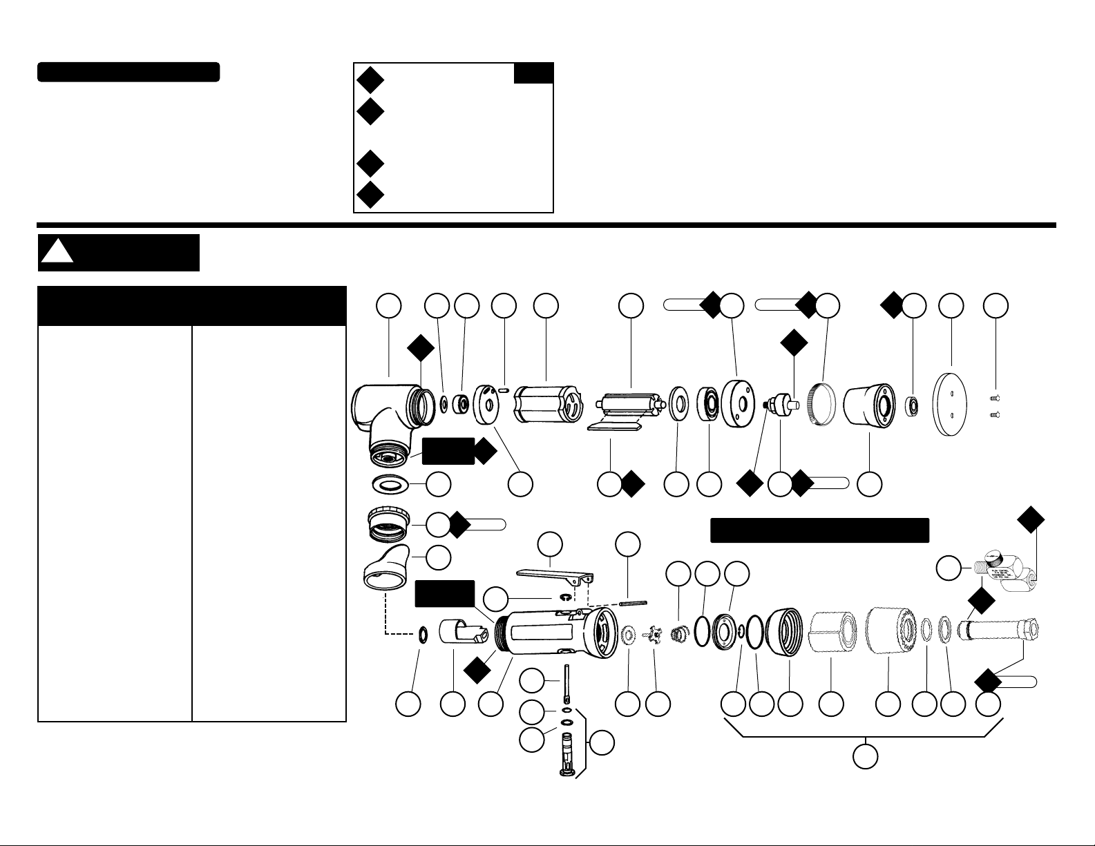
Air Motor and Machine Parts
Oil: O1= Air Lube
G
Grease: G
1
= Lubriplate 630 AA
Index Key
No. Part # Description
1 97328 Screw (2)
2 58030 2" Vinyl Face Pad
3 11016 Bearing
4 57975 Boot Assembly
5 97326 Boot Clamp
Assembly
6 57961 Cam Assembly
7 57962 Exhaust Cover
8 56305 Bearing
9 53161 Front Bearing Plate
10 50777 Rotor
11 01480 Blades (4/pkg.)
12 01476 Cylinder
13 50767 Pin
14 02673 Rear Bearing Plate
15 02696 Bearing
16 02679 Shield
17 57779 Housing
18 01548 Gasket
19 01461 Lock Nut
20 01558 Collar
21 95523 O-Ring
22 01470 Insert
23 95558 Retaining Ring
24 01448 Throttle Lever
01462 Safety Lock Lever
25 12132 Pin
26 57936 Housing
27 01449 Valve Stem
28 95730 O-Ring
29 01024 O-Ring
30 01469 Speed Regulator
Assembly
31 01464 Seal
32 01472 Tip Valve
33 01468 Spring
34 96065 O-Ring
35 57970 Air Control Ring
36 95711 Retaining Ring
37 95438 O-Ring
38 94521 Muffler Base
39 94528 Felt Muffler
40 94522 Muffler Cap
41 95375 O-Ring
42 94526 Spacer
43 94523 Inlet Adapter
44 94519 Muf fler Assembly
45 94407 1/4" Flow Control
12
48
9
10
12
13
14
1517
16
18
20
21 22 26
23
24
25
30
27
28
29
31 32
33
34
35
36 37 38 39 40 41 42
44
45
Right Hand
Threads
A
8
A
8
A
8
O
1
A
2
G
1
A
8
O
1
A
1
45 N•m
T
17 N•m
T
23 N•m
T
0.7 N•m
T
28 N•m
T
Left Hand
Threads
19
11
3
6
5
43
7
57777 Wet Assembly On Page 4.
For Serial No. 2L2948 and Higher
!
WARNING
Page 2

Important Operating, Maintenance and Safety Instructions
Carefully read all instructions before operating or servicing any Dynabrade®Abrasive Power Tool.
Warning: Hand, wrist and arm injury may result from repetitive work motion and overexposure to vibration.
Important: All Dynabrade Rotary Vane air tools must be used with a Filter-Regulator-Lubricator to maintain all warranties.
Operating Instructions:
Warning: Eye, face, respiratory, sound, and body protection must be worn while operating power tools. Failure to do so may result in serious injury or death. Followsafety
procedures posted in workplace.
1. With power source disconnected from tool, securely fasten abrasive /accessory on tool.
2. Install air fitting into inlet bushing of tool. Important: Secure inlet bushing of tool with a wrench before attempting to install the air fitting to avoid damaging
valve body housing.
3. Connect power source to tool. Be careful not to depress throttle lever in the process.
4. Check tool speed with tachometer. If tool is operating at a higher speed than the RPM marked on the tool or operating improperly, the tool should be serviced to correct
the cause before use.
Maintenance Instructions:
1. Check tool speed regularly with a tachometer. If tool is operating at a higher speed than the RPM marked on the tool, the tool should be serviced to correct the
cause before use.
2. Some silencers on air tools may clog with use. Clean and replace as required.
3. All Dynabrade Rotary Vane air motors should be lubricated. Dynabrade recommends one drop of air lube per minute for each 20 SCFM (example: if the tool
specifications state 40 SCFM, set the drip rate of your filter-lubricator at 2 drops per minute).
Dynabrade Air Lube (P/N 95842: 1 pt. 473 ml.) is recommended.
4. An Air Line Filter-Regulator-Lubricator must be used with this air tool to maintain all warranties. Dynabrade recommends the following: 11405Air Line Filter-RegulatorLubricator — Provides accurate air pressure regulation, two-stage filtration of water contaminants and micro-mist lubrication of pneumatic components. Operates 40 SCFM
@ 100 PSIG has 3/8" NPT female ports.
5. Use only genuine Dynabrade replacement parts. To reorder replacement parts, specify the Model #, Serial #, and RPM of your machine.
6. A Motor Tune-Up Kit (P/N 96236)is available which includes assorted parts to help maintain motor in peak operating condition.
7. Mineral spirits are recommended when cleaning the tool and parts. Do not clean tool or parts with any solvents or oils containing acids, esters, keytones, chlorinated
hydrocarbons or nitro carbons.
2
One Y ear Warranty
Following the reasonable assumption that any inherent defect which might prevail in a product will become apparent to the user within one year from the date of purchase, all
equipment of our manufacture is warranted against defects in workmanship and materials under normal use and service. We shall repair orreplace at our factory, any equipment
or part thereof which shall, within one year after delivery to the original purchaser, indicate upon our examination to have been defective. Our obligation is contingent upon proper use of Dynabrade tools in accordance with factory recommendations, instructions and safety practices. It shall not apply to equipment which has been subject to misuse, negligence, accident or tampering in any way so as to affect its normal performance. Normally wearable parts such as bearings, contact wheels, rotor blades, etc., are not covered
under this warranty.
• Important: User of tool is responsible for following accepted safety codes such as those published by the American National Standards Institute (ANSI).
• Operate machine for one minute before application to workpiece to determine if machine is working properly and safely before work begins.
• Always disconnect power supply before changing abrasive/accessory or making machine adjustments.
• Inspect abrasives/accessories for damage or defects prior to installation on tools.
• Please refer to Dynabrade’s Warning/Safety Operating Instructions Tag (Reorder No. 95903) for more complete safety information.
Notice
All Dynabrade motors use the highest quality parts and metals available and are machined to exacting tolerances. The failure of quality pneumatic motors can most often be traced
to an unclean air supply or the lack of lubrication. Air pressure easily forces dirt or water contained in the air supply into motor bearings causing early failure. It often scores the
cylinder walls and the rotor blades resulting in limited efficiency and power. Our warranty obligation is contingent upon proper use of our tools and cannot apply to equipment which
has been subjected to misuse such as unclean air, wet air or a lack of lubrication during the use of this tool.
Safety Instructions:
Products offered by Dynabrade should not be converted or otherwise altered
from original design without expressed written consent from Dynabrade, Inc.
Model Motor Motor Sound Air Flow Rate Air Pressure Weight Length Height
Number HP (W) RPM Level CFM/SCFM (LPM) PSIG (Bars) Pound (kg) Inch (mm) Inch (mm)
57902 .12 (89) 13,000 65 dB(A) 3/20 (566) 90 (6.2) 1.6 (.7) 9 (229) 3-3/4 (95)
Additional Specifications: Air Inlet Thread 1/4" NPT • Hose Size 1/4" (8 mm)
Disassembly /Assembly Instructions - Dynafine
®
Important: Manufacturer’s warranty is void if tool is disassembled before warranty expires
Notice: Dynabrade strongly recommends the use of their 52296 Repair Collar (sold separately) during assembly/disassembly of the Dynafine
®
sander.
All of the special repair tooling referred to in these instructions can be ordered from Dynabrade. Please refer to this parts page for proper part identification.
Motor Disassembly:
1. Disconnect the tool from the air supply.
2. Place the 52296 Repair Collar around the tool and secure it in a vise so that the sanding attachment is facing up.
3. Remove the sanding attachment with the 95266 (3 mm) Hex Key.
Continued on next page.
(PD03•31)
Page 3

3
Disassembly /Assembly Instructions - Dynafine®(Continued)
4. Loosen the 95884 Boot clamp and remove the boot assembly.
5. Use a 3 mm adjustable pin spanner wrench or the 50971 Lock Ring Tool to remove the 57962exhaust Cover by turning it counterclockwise.
6. Pull the exhaust cover along with the motor assembly from the 01546 Housing.
7. Fasten the 96346 (2 in.) Bearing Separator around the end of the 01476 Cylinder that is closest to the 02673 Rear Bearing plate. Place the bearing separator on the table
of the 96232 #2 Arbor Press so that the 57961 Cam Assembly is pointing toward the floor. Use a 3/16" dia. flat end drive punch as a press tool and push the rear stem of
the 50777 Rotor out of the 02696 Bearing.
8. The 02696 Bearing can be removed from the rear bearing plate with a 96210 Bearing Removal Tool and the arbor press.
9. Secure the 50777 Rotor in a vise with an aluminum or bronze jaw and remove the 57961 Cam Assembly by turning it counterclockwise.
10. Remove the front bearing/plate from the 50777 Rotor with a 3/16" dia. flat end drive punch and the arbor press.
Motor Disassembly Complete.
Valve Disassembly:
1. Place the 52296 Repair Collar around the valve housing and secure it in a vise so that the air inlet is pointing up.
2. Use two wrenches to remove the air fitting or the 94407 Flow Control from the 94523 Inlet Adapter.
3. Loosen the 94523 Inlet Adapter from the valve housing and remove the 94520 Muffler Assembly. Note: Use the exploded view of the muffler assembly on the front of this
parts page to identify the specific components and their proper order of assembly.
4. Remove the 12132 Pin and the throttle lever with a drive punch.
5. Use retaining ring pliers to remove the 95558 Retaining Ring and the 01469 Speed Regulator Assembly along with the 01449 Valve Stem.
Valve Disassembly Complete.
Motor Assembly:
Important: Clean and inspect all parts for defects before assembling.
1. Use the 01476 Cylinder as an adjustment jig. Place the cylinder on the table of the arbor press.
2. Position the 50777 Rotor inside the cylinder so that the front face of the rotor is even with the top edge of the cylinder.
3. Install the 53161 Front Bearing Plate onto the rotor and cylinder so that the flat side of plate faces the vane slots of the motor.
4. Place the 56305 Bearing onto the front shaft of the rotor. Using a 96244 Bearing Press Tool, press against the inner race of the bearing pushing it down to the
bearing plate and cylinder.
5. Secure the 50777 Rotor in a soft jaw (aluminum or bronze) vise with bearing plate assembly pointing up.
6. Place the 57962 Exhaust Cover over the bearing/plate assembly.
7. Apply a small amount of #271 Loctite (or equivalent) to the threads of the 57961 Cam Assembly and install it onto the rotor , torque to 17 N•m/150 in.-lbs.
8. Remove this assembly from the vise and install 01480 Vanes that have been lubricated with Dynabrade Air Lube (10W/NR) or (equivalent oil).
9. Place 01476 Cylinder onto the assembly so that the air inlet of the cylinder will line up with the air inlet holes in the 02673 Rear Bearing Plate.
10. Use the 96216 Bearing Press Tool so that the press tool rest against the outer race of the 02696Bearing and press the bearing all the way into the 02673 Rear Bearing Plate.
11. Position the motor assembly in the arbor press with the 57961 Cam Assembly resting on the table of the arbor press. Use the opposite end of the 96216 Bearing Press
Tool so that the press tool rest against the inner race of the 02696 Bearing. Carefully press the rear bearing/plate assembly onto the 50777 Rotor until the 02673 Rear
Bearing Plate comes in contact with the cylinder. Achieve a snug fit between the bearing plates and the cylinder while still being able to push the cylinder from side to side
with a slight force.
12. Apply a small amount of grease to the seal of the 02696 Bearing and position the 02679 Shield against the bearing.
13. Install the motor assembly into the 01546 Housing making sure that it slides all the way in.
14. Apply a small amount of Loctite #567 (or equivalent) to the threads of the 57595 Housing and thread the 57962 Exhaust Cover onto the housing.
15. Apply a small amount of Loctite #609 (or equivalent) to the outer race of the 11016 Bearing. Use the 96243 Bearing Press tool to push against the outer race of the
bearing and press the bearing into the boot assembly.
16. Apply a small amount of the 95542 Grease (or equivalent) to the shaft of the cam assembly and install the boot assembly along with the 95884 Boot Clamp.
17. Tighten 95884 Boot Clamp and torque to .68 N•m/6 in.-lbs.
18. Use the 95266 (3 mm) Hex Key to install the sanding attachment.
Motor Assembly Complete.
Valve Body Assembly:
1. Place the 52296 repair Collar around the valve housing and secure it in a vise so that the air inlet is pointing up.
2. Install the 01469 Speed Regulator Assembly (includes o-rings) along with the 01449 Valve Stem into the valve housing. Secure the speed regulator assembly in the valve
housing with the 95558 retaining Ring.
3. Install the 01464 Seal into the air inlet opening of the valve housing.
4. Line up the hole in the 01449 Valve Stem with the air inlet hole in the valve housing. Use needle nose pliers to insert the 01472 Tip Valve into the air inlet hole of the valve
housing so that the metal stem of the tip valve passes through the hole in the valve stem.
5. Install the 01468 Spring so that the small end of the spring fits onto the back end of the 01472 Tip Valve.
6. Install the 96065 O-Ring onto the 57970 Air Control Ring. When installing these into the valve housing make sure to line up the holes in the air control ring with the
exhaust area of the valve housing.
7. Assemble the 94520 Muffler. Note: Use the exploded view of the muffler assembly on the front of this parts page to identify the specific components and their proper
order of assembly.
8. Apply a small amount of the Loctite #567 (or equivalent) to the threads of the 94523 Inlet adapter and install the muffler assembly onto the valve housing.
(Torque to 23 N•m/200 in.- lbs.)
9. Install the throttle lever and secure it in place with the 12132 Pin.
Tool Assembly Complete. Please allow 30 minutes for adhesives to cure before operating tool.
Throttle Lever Positioning Procedure:
1. Place the 52296 repair Collar around the valve housing and secure it in a vise so that the 01546 Housing is pointing up.
2. Slip the 01558 Collar down onto the valve housing to expose the 01461 Lock Nut.
3. With a firm hold on the 01546 Housing, use a 34 mm or an adjustable wrench to turn the 01461 Lock Nut counterclockwise to loosen the 01546 Housing from the valve housing.
(continued on next page)
Page 4
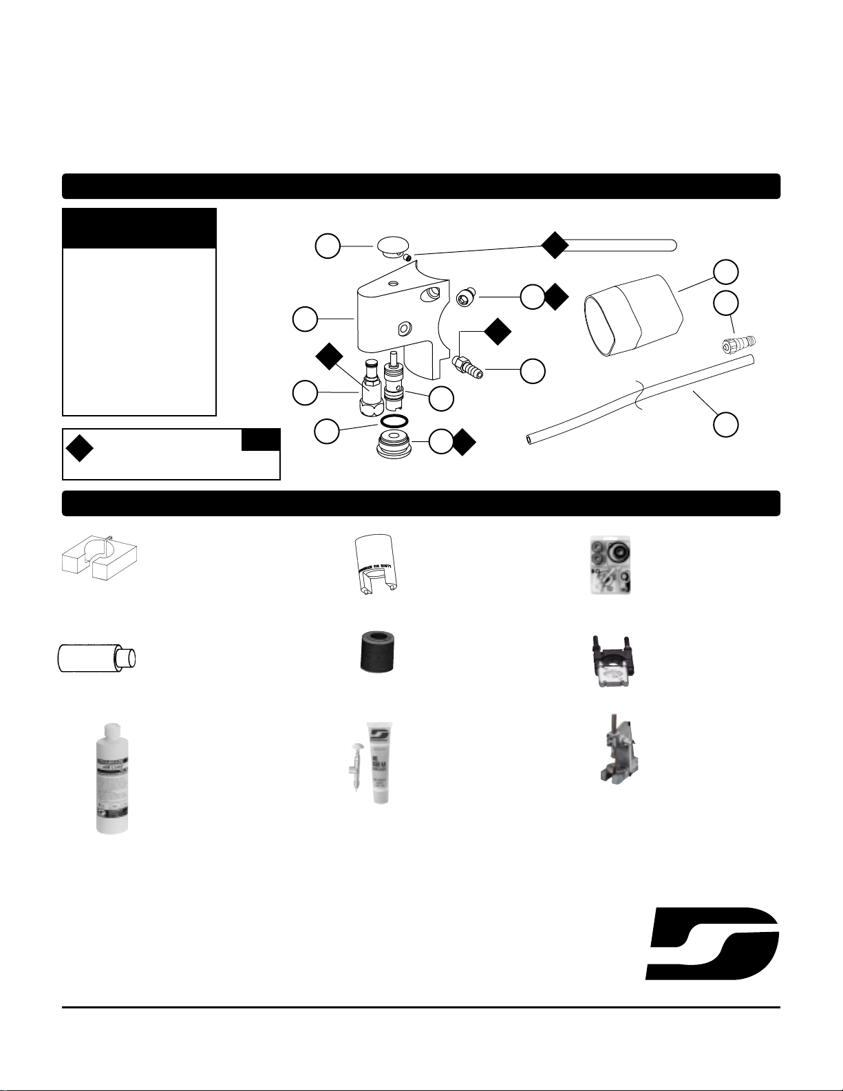
Apply to set screw (included)
Loctite: A2= Loctite #271
A
8
= Loctite #567
KEY
A
Index Key
No. Part # Description
1 57751 Button (w/set screw)
2 57778 Bracket
3 57728 Nozzle
4 57727 Valve Cartridge
5 95523 O-Ring
6 56076 Throttle Valve Plug
7 95074 Hose Fitting
8 97327 Screw (2)
9 95955 10' Tubing
10 10293 Shrink Tube
11 95952 Quick Disconnect
96236 Motor Tune-Up Kit
•
Includes assorted parts to help
maintain and repair motor.
Optional Accessories
57777 Wet Assembly
52296 Repair Collar
• Specially designed collar for use in vise to
prevent damage to valve body housing
during disassembly/ assembly.
96210 Bearing Removal Tool
• This tool is used to pass through the I.D.
of the bearing plate and to push against
the I.D. of the bearing.
96216, 96243, 96244 Bearing Press Tool
• This tool is used to safely press a
bearing plate or onto a shaft.
Dynabrade Air Lube
• Formulated for pneumatic equipment.
• Absorbs up to 10% of its weight in water.
• prevents rust and formation of sludge.
• Keeps pneumatic tools operating longer
with greater power and less down time.
95842: 1pt. (473 ml)
95843: 1 gal. (3.8 L)
50971 Lock Ring Tool
• Lock Ring Tool has a 3/8 in.
square socket for use with 3/8 in.
drive; breaker bar, ratchet head,
or torque wrenches.
DYNABRADE
®
DYNABRADE, INC., 8989 Sheridan Drive • Clarence, NY 14031-1490 • Phone: (716) 631-0100 • Fax: 716-631-2073 • International Fax: 716-631-2524
DYNABRADE EUROPE S.àr.l., Zone Artisanale • L-5485 Wormeldange—Haut, Luxembourg • Telephone: 352 76 84 94 1 • Fax: 352 76 84 95 1
©DYNABRADE, INC., 2003 PRINTED IN USA
Visit Our Web Site: www.dynabrade.com Email: Customer.Service@Dynabrade.com
7
10
11
9
1
5
2
3
4
A
2
A
8
A
2
A
8
A
8
Disassembly /Assembly Instructions - Dynafine®(Continued)
4. Orient the throttle lever to the operators desired grip and positioning. Note: Allow for additional rotation of the 01546 Housing as the 01461 Lock Nut is tightened.
5. With a firm hold on the 01546 Housing to reduce its rotation, use a 34 mm or an adjustable wrench to tighten the 01461 Lock Nut. (Torque to 45 N•m/400 in.- lbs.)
Important: When performing this procedure be careful not to entirely separate the 01546 Housing from the valve body assembly. Loosen the 01461Lock Nut only enough to
make the adjustment.
Motor should now be tested for proper operation at 90 PSIG. If motor does not operate properly or operates at a higher RPM than marked on the tool, the tool
should be serviced to correct the cause before use. Before operating, place 2-3 drops of Dynabrade Air Lube (P/N 95842) directly into air inlet with throttle lever depressed.
Operate tool for 30 seconds to determine if tool is operating properly and to allow lubricating oils to properly permeate motor.
Loctite®is a registered trademark of loctite Corp.
96232 #2 Arbor Press
• This arbor press is ideal for
the disassembly and assembly
of air motors.
96346 Bearing Separator
• Use the separator to remove
bearings and gears.
95542 Grease 10 oz.
• Multi-purpose grease for all types of
bearings, cams, gears.
• High film strength; excellent
resistance to water, steam, etc.
• Workable range 0˚ F to 300˚ F.
95541 Push-type Grease Gun
• One-hand operation.
6
8
 Loading...