

Page 1
GENERAL SAFETY INSTRUCTIONS
Carefully Read and save all instructions before operating or servicing any Dynabrade®Abrasive Power Tool.
Products offered by Dynabrade are not to be modified, converted or otherwise alerted from the original design without expressed written consent from Dynabrade, Inc.
Warning: When using electric tools, basic safety precautions should always be followed to reduce the risk of a fire, electric shock, and personal injury, including the following:
1. Keep work area clean. Cluttered areas and benches invite accidents.
2. Consider work area environment. Do not expose tools to rain. Keep work area well lit. Do not use power tools in damp or wet locations. Do not use tools in the
presence of flammable liquids or gases.
3. Guard against electric shock. Prevent body contact with grounded surfaces. For example; pipes, radiators, ranges, refrigerator enclosures.
4. Keep children away. Do not let visitors contact tool or extension cord. All visitors should be kept away from work area.
5. Store idle tools. When not in use, tools should be stored in a dry, or locked place - out of the reach of children.
6. Do not force tool. It will do a better and safer job at its intended rate.
7. Use the right tool. Do not force a small tool or attachment to do the job of a heavy duty tool. Do not use tool for purposes not intended.
8. Dress properly. Do not wear loose fitting clothing or jewelry. Clothes can be caught in moving parts. Rubber gloves and non-skid footwear are recommended when
working outdoors. Wear protective hair covering to contain long hair.
9. Use safety glasses. Also use face-shield or dust mask if operation area is dusty.
10. Do not abuse cord. Never carry tool by cord or yank it to disconnect from receptacle. Keep cord from heat, oil and sharp edges.
11. Secure work. Use clamps or a vice to hold workpiece. It’s safer than using your hand and it frees up both hands to operate tool.
12. Do not overreach. Keep proper footing and balance at all times.
13. Maintain tools with care. Keep tools clean for better use and safer performance. Follow instructions for lubricating and changing accessories. Inspect tool cords
periodically and if damaged, have repaired by authorized service facility. Inspect extension cords periodically and replace if damaged. Keep handles dry, clean and free
from oil and grease.
Parts Page Reorder No. PD02•42
Effective August, 2002
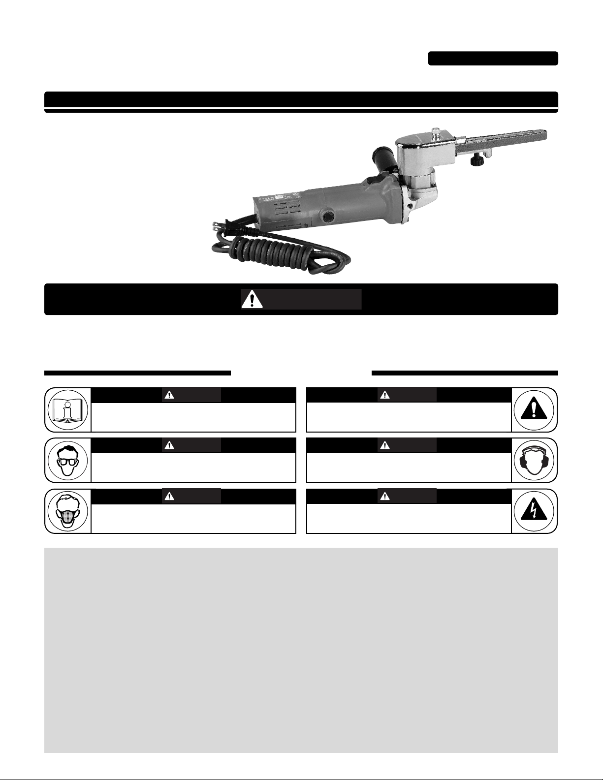
Electric Dynafile
®
II
Tool Manual – Safety, Operation and Maintenance
Models:
40500 – 120 V / 60 Hz
40501 – Versatility Kit
SAFETY LEGEND
G
Read and understand tool manual before
work starts to reduce risk of injury to
operator, visitors, and tool.
Eye protection must be worn at all times,
eye protection to conform to ANSI Z87.1.
Respiratory protection to be used when exposed to
contaminants that exceed the applicable threshold
limit values required by law.
Practice safety requirements. Work alert,
have proper attire, and do not operate tools under
the influence of alcohol or drugs.
Ear protection to be worn when exposure to sound,
exceeds the limits of applicable Federal, State or
local statues, ordinances and/or regulations.
Electric shock hazard. Avoid bodily contact with
grounded objects, bodies of water.
Do not damage cord set.
Read and understand this tool manual before operating your tool. Follow all safety rules for the protection of operating personnel
as well as adjacent areas. For safety information, refer to Safety Requirements for the Use, Care and Protection of Abrasive Wheels
– ANSI B7.1, Code of Federal Regulation – CFR 29 Part 1910, European Committee for Standards (EN) Hand Held Electric Motor
Operated Tools – Safety Requirements and applicable State and Local Regulations.
SAVE THIS DOCUMENT, EDUCATE ALL PERSONNEL
For Serial No. 2H1000A and Higher
WARNIN
WARNING
WARNING
WARNING
WARNING
WARNING
WARNING
Page 2

2
14. Do not leave tool running. Disconnect tools when not in use, before servicing, when changing belts, contact arms, etc.
15. Remove keys and wrenches. Form a habit of checking to see that all keys and adjusting wrenches are removed from tool before turning it on.
16. Avoid accidental starting. Do not carry around plugged in tool with finger on slide switch. Be sure switch is off when plugging in.
17. Out-door use extension cords. When tool is used outdoors, use only extension cord suitable for outdoor use. They should be marked with the suffix W-A (for UL) or
W (for CSA in Canada).
18. Stay alert. Watch what you are doing. Use common sense. Do not operate tool when you are tired.
19. Check damaged parts. Before further use of the tool, a guard or other part that is damaged should be carefully checked to determine that it will operate properly and
perform its intended function. Check for alignment of moving parts, breakage of moving parts, binding of moving parts, mounting and any other conditions that may affect
its operation. A guard or other part that is damaged should be properly repaired or replaced by an authorized service center unless otherwise indicated elsewhere in this
instruction manual. Have defective switches replaced. Do not use tool if switch does not turn tool on or off.
20. Avoid gaseous areas. Do not operate portable electric tools in gaseous or explosive atmospheres. Motors in these tools normally spark, and the sparks can ignite fumes.
21. Do not alter or misuse tool. This tool is precision built. Any alteration or modification not specified is misuse and may result in a dangerous condition. Only these
accessories and attachments that are found in this instruction manual are acceptable for use with this tool. The use of any other accessory or attachment might present a
risk to the operator.
22. Replacement parts. When servicing, use only identical replacement parts. When ordering replacement parts, please specify model and serial numbers of your machine.
Voltage Warning
Before connecting the tool to a power source (receptacle, outlet, etc.), be sure the voltage supplied is the same as what is specified on the nameplate of the tool. A power
source with greater than that specified for tool can result in serious injury to the user as well as damage to the tool. Using a power source with voltage less than the
nameplate rating is harmful to the tool’s motor. If in doubt, do not plug in the tool.
Double Insulation
Your Electric Dynafile
®
II is double-insulated to give you added safety. This means that the tool is constructed throughout with two separate “layers” of electrical
insulation, or one double thickness of insulation between you and the tool’s electrical system. Tools built with this type of insulation system are not intended to be
grounded. As a result, your Electric Dynafile
®
II is equipped with a two prong plug which permits you to use extension cords without concern for maintaining a ground connection.
Note: Double-insulation does not take the place of normal safety precautions when operating this tool. The insulation system is added for protection against injury
resulting from a possible electrical insulation failure within the tool.
Caution: When servicing double-insulated tools, use only identical replacement parts. Repair or replace damaged cords.
Extension Cords
Double-insulated tools have two-wire cords, and can be used with either two-wire or three-wire extension cords. Only round jacketed extension cords should be used, and
we recommend that they be listed by Underwriters Laboratories (UL) - (CSA in Canada). If the extension cords will be used outside, the cord must be suitable for outdoor
use. They should be marked with the suffix W-A (for UL) or W (for CSA in Canada). Any cord marked as an outdoor cord can also be used for indoor work.
Polarized Plugs: To reduce the risk of electric shock, this equipment has a polarized plug (one blade is wider than the other). This plug will fit in a polarized outlet only one way.
If the plug does not fit in the outlet, reverse the plug. If it still does not fit, contact a qualified electrician to install the proper outlet. Do not change the plug in any way.
Warning: Keep extension away from the immediate working area.
Abrasive Impregnated Non-Woven Nylon
A non-woven synthetic fiber and an abrasive mineral are bonded together to
form a tough, open web that is chemically resistant and long-lasting. This web
design allows controlled conformable contact to workpiece contours, corners
and edges. The product wears away slowly, exposing new abrasive leaving a
uniform, consistent surface. It also conditions surfaces without removing or
damaging the base material and is excellent for deburring, cleaning, blending
and final finishing of metal, wood and plastics. It is available in many forms
such as belts, discs and wheels. Various mineral grades are available
ranging from very coarse to ultra-fine.
Cloth Polishing Belts
Used on power tools in conjunction with Dynuba®polishing compounds. The
result is brilliant cut, color and luster on metals such as stainless steel, aluminum, copper and brass.
Coated Aluminum Oxide
The most widely used abrasive grain. This tough durable synthetic is used for
grinding and deburring high carbon steels, general metalworking and for
sanding certain hardwoods.
Ceramic Coated Aluminum Oxide
Synthetic grain two-to-three times tougher than conventional aluminum oxide.
Coated Silicon Carbide
Excellent for sanding primer and sealer. This sharp, fast-penetrating grain is
used for sanding soft materials such as plastics and fibrous wood.
Coated Alumina Zirconia
Effective for coarse stock removal of metal and wood. This synthetic grain has
self-sharpening characteristics and provides continuous new cutting edges for
longer life and greater efficiency.
Abrasive Types and Cloth Polishing Belts
All abrasive accessories may be found in the most current Dynabrade®Catalog and abrasive literature.
Dynapad®Platen Pads
Note: Dynapad Platen Pads are PSA mounted and easily trimmed to size.
Exceptions: 11024 and 11028 Steel Platens bolt on; 14341 clamps on.
Unit = 10 packages each.
Part Pkg.
Number Size Material Qty.
11024 1/2" W x 3" L (bolts on) Steel 1
11025 1/2" W x 7" L x 1/8" Thk Soft/Sponge 5
11026 1/2" W x 7" L x 1/8" Thk Hard/ Cork 5
11027 1/2" W x 7" L x 1/32" Thk Thin 5
11109 3/4" W x 7" L x 1/8" Thk Hard/ Cork 5
11119 3/4" W x 7" L x 1/8" Thk Soft/ Sponge 5
11129 3/4" W x 7" L x 1/32" Thk Thin 5
Page 3

Important Operating and Safety Instructions
Carefully read all instructions before operating or servicing any Dynabrade®Abrasive Power Tool.
Warning: Hand, wrist and arm injury may result from repetitive work motion and overexposure to vibration.
Operating Instructions:
Warning: Eye, face, respiratory, sound and body protection must be worn while operating power tools. Failure to do so may result in serious injury or death.
Follow safety procedures posted in workplace.
1. With power source disconnected from tool, securely fasten abrasive/accessory on tool.
2. Connect power source to tool. Be careful not to depress switch in the process.
3. Hold tool by the motor housing only. One or two hands may be used. Do Not hold tool by head/housing assembly. Keep hands away from all grinding/sanding
edges and moving parts. A side handle is included for two hand operation of tool. (See “Installing Side Handle” Instructions.)
4. Slide and rock slide switch forward to start tool. Touch rear of side switch to release.
5. While tool is running, adjust belt tracking by turning 95218 Rough Adjustment Knob to the left or right accordingly, so as abrasive belt rides evenly over contact arm.
6. Always work off the return side of the abrasive belt. this will ensure superior tracking and reduce downtime of tool.
Abrasive Belt/Contact Arm Change Instructions:
To Change Belt: To Change Contact Arm Assembly:
1. Disconnect power source. 1. Disconnect power source.
2. Remove 40365 Belt Guard by pulling backwards and 2. Remove 40365 Belt Guard by pulling backwards and
upwards over the 40314 Button Latch Assembly. upwards over the 40314 Button Latch Assembly.
3. Pull back on tension arm assembly. 3. Pull back on tension arm assembly and remove abrasive belt.
4. Remove and replace abrasive belt and belt guard. 4. Remove 95218 Rough Adjustment Knob.
5. Connect power source. 5. Remove contact arm and replace with desired arm, making sure
6. Adjustment belt is tracking by turning 95218 Rough Adjustment Knob
that the tab on the end of the arm is facing downward.
to the left or right accordingly while machine is running. 6. Replace 95218 Knob.
7. Install abrasive belt and replace belt guard.
8. Connect power source and adjust belt tracking by turning 95218 Knob.
Housing Angle Adjustment: To pivot housing, loosen 95311 Screw on housing with the supplied 9/64" hex wrench (P/N – 95134). Pivot housing to desired angle
and retighten 95311 Screw.
Installing Side Handle: The side handle may be installed on either side of the gear case for right or left hand operation. Position the side handle on the side
offering the best comfort and control of the tool. To install, thread side handle into side handle socket on desired side of gear case and tighten securely.
Maintenance Instructions
Important: A Preventative Maintenance Program is recommended whenever portable power tools are used.
• Use only genuine Dynabrade replacement parts to insure quality. To order replacement parts, specify Model #, Serial # and RPM of your tool.
Routine Preventative Maintenance: Check free speed of Electric Dynafile
®
II using a tachometer.
• Mineral spirits are recommended when cleaning the sanding heads. Do not use on electrical components or clean tool or parts with any solvents or oils
containing acids, esters, ketones, chlorinated hydrocarbons or nitro carbons. Blow the dirt from electrical components with air.
• DO NOT
clean or maintain tools with chemicals that have a low flash point (example: WD-40®).
• Tool labels must be kept legible at all times, if not, reorder label(s) and replace. User is responsible for maintaining specification information i.e.:
Model #, S/N, and RPM. (See Assembly Breakdown)
• Visually inspect plugs and cords for frays, visible damage and signs of deterioration. Replace damaged or worn components.
• Refer to Dynabrade's Warning/Safety Operating Instructions Tag (Reorder No. 95903) for safety information.
• Brush Changing – When the brushes wear down to a predetermined length, the tool is automatically shut off to prevent damage to the armature. Unplug tool and
remove brush caps (item #23) and replace brushes (item #22). Replace brush caps.
After maintenance is performed on tool check for excessive tool vibration. Check for excessive current leakage at 550 volts with a current leakage checker on all
screws and the gear case, if the electrical components have been disturbed during repair.
Handling and Storage:
• Use of tool rests, hangers and/or balancers is recommended.
• DO
NOT carry tool by cord.
• Protect abrasive accessories from exposure to water, solvents, high humidity, freezing temperature and extreme temperature changes.
• Store accessories in protective racks or compartments to prevent damage.
One Year Warranty
Following the reasonable assumption that any inherent defect which might prevail in a product will become apparent to the user within one year from the date of purchase, all equipment of our manufacture is warranted against defects in workmanship and materials under normal use and service. We shall repair or replace at our
factory, any equipment or part thereof which shall, within one year after delivery to the original purchaser, indicate upon our examination to have been defective. Our
obligation is contingent upon proper use of Dynabrade tools in accordance with factory recommendations, instructions and safety practices. It shall not apply to
equipment which has been subject to misuse, negligence, accident or tampering in any way so as to affect its normal performance. Normally wearable parts such as
bearings, contact wheels, rotor blades, etc., are not covered under this warranty.
Machine Specifications
3
Model Motor Motor Abrasive Belt Size Max. SFPM Weight Length Height
Number RPM Hp Inch (mm) Voltage Current Phase Frequency (SMPM) Pound (kg) Inch (mm) Inch (mm)
40500 12,000 1 1/4-3/4 (6-19) W x 18-24 (457-610) L 120 V (AC) 5 Amps 1 60 Hz 2,600 (790) 4.8 (2.2) 14.5 (356) 5.0 (127)
Page 4

Extension Cords
Double insulated tools can use either a two or three wire extension cord. As the distance from the supply outlet increases, you must use a heavier gauge
extension cord. Using extension cords with inadequately sized wire causes a serious drop in voltage resulting in loss of power and possible tool damage.
Refer to the table below to determine the required minimum wire size.
The smaller the gauge number of the wire the greater the capacity of the cord. For example a 14 gauge cord can carry a higher current than a 16 gauge
cord. When using more than one extension cord to make up the total length, be sure each cord contains at least the minimum wire size required. If you are
using one extension cord for more than one tool, add the nameplate ampere and use the sum to determine the required minimum wire size.
Guidelines For Using Extension Cords
• If you are using an extension cord outdoors, be sure it is marked with the suffix “W-A” (“W” in Canada) to indicate that it is acceptable for outdoor use.
• Be sure your extension cord is properly wired and in good electrical condition. Always replace a damaged extension cord or have it repaired by a qualified
person before using it.
• Protect your extension cords sharp objects, excessive heat and damp or wet areas.
Read and save all instructions for future reference.
4
Housing Assembly
Note: Shaded parts represent 15372 Housing Assembly.
Nameplate Extension Cord Length
Ampere 25' 50' 75' 100' 150' 200'
0–5.0 16 16 16 14 12 12
5.1–8.0 16 16 14 12 10 –
8.1–12.0 14 14 12 10 – –
12.1–15.0 12 12 10 10 – –
15.1–20.0 10 10 10 – – –
*Based on limiting the line
voltage drop to live volts at
150% of the rated ampere.
1 Contact Arm Assembly
(See Chart on pg.6)
2 96334 Plug
3 15308 Guide Post
4 11040 Spring
5 15306 Tension Arm
6 95426 Spring
7 95218 Knob Assembly
8 15309 Dust Cover
9 15307 Tension Shaft
10 15329 Screw
11 15312 Belt Guard
12 96335 Hex Nut
13 15366 Housing
14 95311 Screw
15 40029 Motor Lock
16 95217 Screw
17 15316 Drive Wheel
18 40505 Motor Assembly
Index Key
No. Part # Description
17
15
13
14
12
11
10
9
8
6
7
5
1
16
3
2
4
18
Page 5

Angle-Head Assembly and Assemblies
5
To order replacement parts,
specify model number and
serial number of your machine.
1 42710 Screw (4)
2 42711 Gear Case Cover
3 42712 Spindle 3/8"-24
4 42713 Key
5 42714 Lower Spindle Bearing
6 42715 Screw (2)
7 42716 Bearing Retainer
8 42717 Gear Spacer
9 42718 Gear/Pinion Set
10 42719 Retaining Ring
11 42720 Upper Spindle Bearing
12 42721 Lock Pin
13 42722 Screw (4)
14 42723 Gear Case Assembly
(Includes: #12, #15 & #16)
15 42724 Lock Spring
16 42725 Lock Button
17 42726 Side Handle
18 42729 Switch
21
1
3
2
4
5
6
7
8
9
10
11
12
17
15
16
18
14
13
26
19 42730 Cord Protector
20 42731 Cord Set
21 42732 Brush Holder (2)
22 42733 Brush (2)
23 42734 Brush Cap (2)
24 42735 Brush Set Assembly
25 42746 Nut
26 42728 Electric Motor Assembly
(Includes 42718 Gear/Pinion Set)
Index Key
No. Part # Description
Electric Motor
Assembly
19
20
Brush Set
Assembly
23
22
24
25
Page 6

Electric Dynafile
®
II Contact Arms
Optional 40078 Adapter allows use
of 24" long belts; extends reach to
7" when used with contact arm.
Arms for 4" to 17" workable reach.
* Note: For belt widths greater than 1/2" use drive wheel 15336 to eliminate slippage.
45 PSI maximum.
Enter channels as
small as 7/16".
Belt Size: 1/2" W x 18" L.
Contact Wheel: 5/16" dia. x 3/8" W, rubber.
Platen: 1/2" wide.
Work on broad areas, leaves
in-line scratch, blend stainless.
11200
11024 steel platen available.
6-3/4" workable reach.
11286
Belt Size: 1/2" W x 24" L.
Contact Wheel: 5/8" dia. x 3/8" W, rubber. Platen: 1/2" wide.
Grind on contact wheel
or platen; has 5-1/4"
workable reach.
11201
Belt Size: 1/2" W x 18" L.
Contact Wheel: 5/16" dia. x 3/8" W, steel.
Platen: 1/2" wide.
11202
Enter 5/16" x 3/4" openings.
Belt Size: 1/4" W x 18" L.
Contact Wheel: 5/8" dia. x 1/8" W, rubber.
Platen: 1/4" wide.
11287* Uses 20-1/2" Belts
Belt Size: 5/8" or 3/4" W x 20-1/2" L
Contact Wheel: 3/4" dia. x 5/8" W, rubber. Platen: 3/4" wide.
11304 “The Banana Arm”
Work on broad areas;
leaves in-line scratch;
blend stainless.
Belt Size: 1/2" W x 18" L.
Contact Wheel: 5/8" dia. x 3/8" wide, rubber. Platen: 1/2" wide.
2-1/2"
Rubber
11322 Guide-Cut
Removes raised material within
.020" or less without undercutting.
Guide Wheels
Prevent Undercutting
Belt Size: 1/2" W x 18" L. 60 to 80 grit.
Contact Wheel: 5/8" dia. x 3/8" W, rubber.
11329 Extra Length Arm
17" workable reach.
Belt Size: 1/2" W x 44" L.
Contact Wheel: 5/8" dia. x 3/8" W, rubber. Platen: 1/2" wide.
11350* “Bus Bar”
Excellent for cleaning oxide
off electrical bus bars. Arm
has a 12" workable reach.
Belt Size: 3/4" W x 34" L.
Contact Wheel: 5/16" dia. x 5/8" W, steel. Platen: 3/4" wide, optional.
11220*, 11300*, 11301*, 11341*
Polish Turbine Blades
Offset design and miniature
contact wheels. 2" strap polish
in offset area; polish turbine
blades and other contours.
11203* Order 11312 for heavy-duty version.
Grind over contact
wheel or platen.
Belt Size: 1/2" W x 18" L.
Contact Wheel: 5/8" dia. x 3/8" W, rubber. Platen: 1/2" wide.
11204 – “Unique Offset Design”
Strap polish is easy with this arm!
Belt Size: 1/4" or 1/2" W x 18" L.
Contact Wheel: 1" dia. x 3/8" W, rubber. Platen: None due to offset design.
11206*
Belt Size: 5/8" or 3/4" W x 18" L.
Contact Wheel: 3/4" dia. x 5/8" wide, rubber. Platen: 3/4" wide.
taperedStrap polish here
Order 11326 for Heavy Duty/Steel Construction version.
11280
Belt Sizes: 11220 uses 5/8" or 3/4" W x 18" L.
All others use 1/2" W x 18" L.
Contact wheels description for each above arm:
11220: 5/16" dia. x 5/8" W, steel. 11300: 1/4" dia. x 3/8" W, steel.
11301: 5/16" dia. x 3/8" W, steel. 11341: 5/16" dia. x 3/8" W, rubber.
Belt Size: 1/4" W x 18" L.
Contact Wheel: 1" dia. x 3/8" wide, urethane, tapered.
Platen: No platen due to offset design.
*Standard Contact Arm for Electric Dynafile
®
II
Grind corners, enter
grooves, strap polish.
6
Page 7

Electric Dynafile®II Standard Contact Arms
7
Part Abrasive Contact Wheel Contact Wheel Contact Wheel Bearing
Number Belt Size Description Comments Assembly Only (2) Req. Shaft
11200 1/2" x 18" 5/8" Dia. x 3/8" W Rubber “Stroke-Sander Arm” 11088 (2) 11077 (2) 11052 (4) 11055 (2)
1/2" W Platen
11201 1/2" x 18" 5/16" Dia. x 3/8" W Steel 1/2" W Platen 11068 11067 11051 11054
11202 1/4" x 18" 5/8" Dia. x 1/8" W Rubber 1/4" W Platen 11074 11073 11052 11053
11203 1/2" x 18" 5/8" Dia. x 3/8" W Rubber 1/2" W Platen 11078 11077 11052 11054
11204 1/4" or 1/2" x 18" 1" Dia. x 3/8" Wide Loose Belt Application 11080 11079 11052 11054
Radiused Rubber
11206 5/8" or 3/4" x 18" 3/4" Dia. x 5/8" W Rubber 3/4" W Platen 11282 11281 11052 11285
11220 5/8" or 3/4" x 18" 5/16" Dia. x 5/8" W Steel Polish Turbine Blades 11352 11353 11051 11285
11280 1/4" x 18" 1" Dia. x 3/8" Wide No Platen /Offset Design 11086 11085 11052 11054
Tapered Urethane
11286 1/2" x 24" 5/8" Dia. x 3/8" W Rubber 1/2" W Platen 11078 11077 11052 11054
11287 5/8" or 3/4" x 20-1/2" 3/4" Dia. x 5/8" W Rubber 3/4" W Platen 11282 11281 11052 11285
11300 1/2" x 18" 1/4" Dia. x 3/8" W Steel Polish Turbine Blades 11332 11333 11334 11335
11301 1/2" x 18" 5/16" Dia. x 3/8" W Steel Polish Turbine Blades 11068 11067 11051 11054
11304 1/2" x 18" 5/8" Dia. x 3/8" W Rubber “Stroke-Sander Arm”-1/2" W Platen 11078 11077 11052 11054
11312 1/2" x 18" 5/8" Dia. x 3/8" W Rubber H.D. Version of 11203 Arm 11078 11077 11052 11054
11320 1/2" x 18" 5/8" Dia. x 3/8" W Rubber “Offset Arm” – prevent gouging. 11078 11077 11052 11054
11322 1/2" x 18" 5/8" Dia. x 3/8" W Rubber Contains two 11395 Guide 11090 11077 11052 95610
Wheels – Prevents Undercutting
11325 1/2" x 18" 5/8" Dia. x 3/8" W Rubber 1/2" W Steel Platen 11078 11077 11052 11054
11326 5/8" or 3/4" x 18" 3/4" Dia. x 5/8" W Rubber H.D. Version of 11206 Arm 11282 11281 11052 11285
11329 1/2" x 44" 5/8" Dia. x 3/8" W Rubber 1/2" W Platen/ 17" Reach 11078 11077 11052 11054
11341 1/2" x 18" 5/16" Dia. x 3/8" W Rubber Polish Turbine Blades 11342 11343 11334 11335
11350 3/4" x 34" 5/16" Dia. x 5/8" W Steel Bus Bar Arm/12" Reach 11352 11353 11051 11285
Electric Dynafile®II Contact Arm Assembly Parts List
Contact Wheel Assembly – Includes wheel, bearings and shaft.
Contact Arm
Shaft
Bearing
Contact Wheel
Bearing
Contact Arm Assembly/Disassembly Instructions
11275 CONTACTWHEEL SHAFT
REMOVAL TOOL
11271 WHEEL POSITION BLOCK
11271 WHEEL POSITION BLOCK
11276 BEARING REMOVALTOOL
FOR 1/4" ID CONTACT WHEEL
11277 BEARING REMOVALTOOL FOR
3/8" ID CONTACT WHEEL
11274 CONTACTWHEEL BEARING
MOUNT TOOL
11279 CONTACTWHEEL SHAFT
ADHESIVE
CONTACT WHEEL SHAFT
SLIP FIT
PRESS
FIT HERE
BEARING
PRESS FIT
SLIP FIT
CONTACT WHEEL
CONTACT WHEEL
REMOVE OLD BEARING FROM WHEEL
PRESS BEARING INTO EACH SIDE OF WHEEL
INSTALL NEW SHAFT
REMOVE CONTACT ARM FROM MACHINE.
PRESS CONTACT WHEEL SHAFT OUT OF CONTACT ARM.
MOISTEN TIP OF PIPE CLEANER WITH CONTACT WHEEL
SHAFT ADHESIVE AND APPLY TO ID OF BEARINGS BEFORE
INSTALLING PROPER SHAFT.
DO NOT GET ADHESIVE ON FACE OF BEARING.
INSERT INTO
BORE OF BEARING
PIPE CLEANER
11271 WHEEL POSITION BLOCK
5
4
1
2
3
Page 8

DYNABRADE
®
DYNABRADE, INC., 8989 Sheridan Drive • Clarence, NY 14031-1490 • Phone: (716) 631-0100 • Fax: 716-631-2073 • International Fax: 716-631-2524
DYNABRADE EUROPE S.àr.l., Zone Artisanale • L-5485 Wormeldange—Haut, Luxembourg • Telephone: 352 76 84 94 1 • Fax: 352 76 84 95 1
© DYNABRADE, INC., 2002 PRINTED IN USA
Visit Our Web Site: www.dynabrade.com Email: Customer.Service@Dynabrade.com
Optional Accessories
11288 Dynafile Contact Arm
and Idler Wheel Repair Kit
• Contains special tools to assist in the
replacement of contact wheels and bearings.
1. American National Safety Institute – ANSI
24 West 43
rd
Street
Fourth Floor
New York, NY 10036
Tel: 1 (212) 642-4900
Fax: 1 (212) 398-0023
3. European Committee for Standardization
Rue de Stassart 36
B - 1050 Brussels, Belgium
2. Government Printing Office – GPO
Superintendent of Documents
Attn. New Orders
P.O. Box 371954
Pittsburgh, PA 15250-7954
Tel: 1 (202) 512-1803
Reference Contact Information
 Loading...