

Page 1

Parts Page Reorder No. PD95•45
Effective September, 1995
40500 – 120V / 60Hz
40501 – Kit 120V / 60Hz
Models:
Abrasive Belt Machine
Electric Dynafile®II
Always operate, inspect and maintain this tool in accordance with the safety standards established by
OSHA, Underwriters Laboratories, Inc., The Canadian Standards Association and The American National
Standards Institute (ANSI). Dynabrade, Inc. assumes no responsibility for any damage or accidents
resulting from the misuse of this tool, its misapplication or nonadherence to precautionary safety measures.
General Safety Rules
Read and save all instructions before operating this power tool.
Warning:
When using electric tools, basic safety precautions should always be followed
to reduce the risk of a fire, electric shock, and personal injury,
including the following:
1. Keep work area clean. Cluttered areas and benches invite accidents.
2. Consider work area environment. Do not expose tools to rain. Keep
work area well lit. Do not use power tools in damp or wet locations.
Do not use tools in the presence of flammable liquids or gases.
3. Guard against electric shock. Prevent body contact with grounded surfaces.
For example; pipes, radiators, ranges, refrigerator enclosures.
4. Keep children away. Do not let visitors contact tool or extension cord. All
visitors should be kept away from work area.
5. Store idle tools. When not in use, tools should be stored in a dry, or locked
up place - out of the reach of children.
6. Do not force tool. It will do a better and safer job at its intended rate.
7. Use the right tool. Do not force a small tool or attachment to do the job of
a heavy duty tool. Do not use tool for purposes not intended.
8. Dress properly. Do not wear loose fitting clothing or jewelry. They can be
caught in moving parts. Rubber gloves and non-skid footwear are recommended
when working outdoors. Wear protective hair covering to contain long hair.
9. Use safety glasses. Also use face-shield or dust mask if operation area is dusty.
10.Do not abuse cord. Never carry tool by cord or yank it to disconnect from
receptacle. Keep cord from heat, oil and sharp edges.
11.Secure work. Use clamps or a vice to hold workpiece. It’s safer than using
your hand and it frees up both hands to operate tool.
12.Do not overreach. Keep proper footing and balance at all times.
13.Maintain tools with care. Keep tools clean for better use and safer
performance. Follow instructions for lubricating and changing accessories.
Inspect tool cords periodically and if damaged, have repaired by authorized
service facility. Inspect extension cords periodically and replace if
damaged. Keep handles dry, clean and free from oil and grease.
14.Do not leave tool running. Disconnect tools when not in use, before
servicing, when changing belts, contact arms, etc.
15.Remove keys and wrenches. Form a habit of checking to see that all
keys and adjusting wrenches are removed from tool before turning it on.
16.Avoid accidental starting. Do not carry around plugged in tool with finger
on lever. Be sure lever is off when plugging in.
17.Out-door use extension cords. When tool is used outdoors, use only
extension cord suitable for outdoor use. They should be marked with the
suffix W-A(for UL) or W (for CSAin Canada).
18.Stay alert. Watch what you are doing. Use common sense. Do not
operate tool when you are tired.
19.Check damaged parts. Before further use of the tool, a guard or other part
that is damaged should be carefully checked to determine that it will operate
properly and perform its intended function. Check for alignment of moving
parts, breakage of moving parts, binding of moving parts, mounting and any
other conditions that may affect its operation. Aguard or other part that is
damaged should be properly repaired or replaced by an authorized
19.(Cont.) service center unless otherwise indicated elsewhere in this
instruction manual. Have defective switches replaced. Do not use
tool if switch does not turn tool on or off.
20.Avoid gaseous areas. Do not operate portable electric tools in
gaseous or explosive atmospheres. Motors in these tools normally
spark, and the sparks can ignite fumes.
21.Do not alter or misuse tool. This tool is precision built. Any
alteration or modification not specified is misuse and may result in a
dangerous condition. Only these accessories and attachments that
are found in this instruction manual are acceptable for use with this
tool. The use of any other accessoryor attachment might present a risk
to the operator.
22.Replacement parts. When servicing, use only identical replacement
parts. When ordering replacement parts, please specify model and
serial numbers of your machine.
Voltage Warning
Before connecting the tool to a power source (receptacle, outlet, etc.)
be sure the voltage supplied is the same as what is specified on the
nameplate of the tool. Apower source with greater than that specified
for tool can result in serious injury to the user as well as damage to
the tool. Using a power source with voltage less than the nameplate
rating is harmful to the tool’s motor. If in doubt, do not plug in the tool.
Double Insulation
Your Electric Dynafile® II is double-insulated to give you added
safety. This means that the tool is constructed throughout with two
separate “layers” of electrical insulation, or one double thickness of
insulation between you and the tool’s electrical system.
Tools built with this type of insulation system are not intended to be
grounded. As a result, your Electric Dynafile® II is equipped with a two
prong plug whichpermits you to use extension cords without concern for
maintaining a ground connection.
Note: Double-insulation does not take the place of normal safety
precautions when operating this tool. The insulation system is added
for protection against injury resulting from a possible electrical
insulation failure within the tool.
Caution: When servicing double-insulated tools, use onlyidentical
replacement parts. Repair or replace damaged cords.
Extension Cords
Double-insulated tools have two-wire cords, and can be used with
either two-wire or three-wire extension cords. Only round jacketed
extension cords should be used, and we recommend that they be listed
by Underwriters Laboratories (UL) - (CSAin Canada). If the extension
cords will be used outside, the cord must be suitable for outdoor use.
They should be marked with the suffix W-A(for UL) or W (for CSAin
Canada). Any cord marked as an outdoor cord can also be used for
indoor work.
Polarized Plugs: To reduce the risk of electric shock, this equipment has
a polarized plug (one blade is wider than the other). This plug will fit in
a polarized outlet only one way. If the plug does not fit in the outlet,
reverse the plug. If it still does not fit, contact a qualified electrician to
install the proper outlet. Do not change the plug in any way.
Warning: Keep extension away from the immediate working area.
!
WARNING
Page 2

Important Operating and Safety Instructions
Carefully read all instructions before operating or servicing any Dynabrade® Abrasive Power Tool.
Warning:Hand, wrist and arm injury may result from repetitive work motion and overexposure to vibration.
Operating Instructions:
Warning: Eye, face and body protection must be worn while operating power tools. Failure to do so may result in serious injury or death.
Follow safety procedures posted in workplace.
1. With power source disconnected from tool, securely fasten abrasive/accessory on tool.
2. Connect power source to tool. Be careful not to depress paddle switch in the process.
3. Hold tool by the motor housing only. One or two hands may be used. Do Nothold tool by head/housing assembly. Keep hands away from all
grinding/sanding edges and moving parts. Aside handle is included for two hand operation of tool. (See “Installing Side Handle” instructions.)
4. Depress paddle switch (trigger) and hold to start tool. Release switch to stop tool.
5. While tool is running, Adjust belt tracking by tuning 95218 Rough Adjustment Knob to the left or right accordingly, so as abrasive belt rides
evenly over contact arm.
6. Always work off the return-side of the abrasive belt. This will ensure superior tracking and reduce downtime of tool
Housing Angle Adjustment:
To pivot housing, loosen 95311Screw on housing with the supplied 9/64" hex wrench (P/N – 95134). Pivot housing to desired angle and
retighten 95311Screw.
Installing Side Handle:
The side handle may be installed on either side of the rotor housing for right or left hand operation. Position the side handle on the side offering the
best comfort and control of the tool. To install, thread side handle into side handle socket on desired side of motor housing and tighten securely.
Safety Instructions:
• Warning:Eye, face and body protection must be worn while operating power tools. Failure to do so may result in serious injury or death.
Follow safety procedures posted in workplace.
• Important: User of tool is responsible for following accepted safety codes such as those published by the American National
Standards Institute (ANSI).
• Operate machine for 30 seconds before application to workpiece to determine if machine is working properly and safely before work begins.
• Always disconnect power supply before changing abrasive or making machine adjustments.
• Inspect abrasives and accessories for damage or defects prior to installation on tools.
• Please refer to Dynabrade’s Warning/Safety Operating Instructions Tag (Reorder No. 95903) for more complete safety information.
• Warning:Hand, wrist and arm injury may result from repetitive work, motion and overexposure to vibration.
2
Full One Year Warranty
Following the reasonable assumption that any inherent defect which might prevail in a product will become apparent to the user within one
year from the date of purchase, all equipment of our manufacture is warranted against defects in workmanship and materials under normal
use and service. We shall repair or replace at our factory, any equipment or part thereof which shall, within one year after delivery to the
original purchaser, indicate upon our examination to have been defective.
Our obligation is contingent upon proper use of Dynabrade tools in accordance with factory recommendations, instructions and safety
practices. It shall not apply to equipment which has been subject to misuse, negligence, accident or tampering in any way so as to affect its
normal performance. Normally wearable parts such as bearings, contact wheels, rotor blades, etc., are not covered under this warranty.
Abrasive Belt/Contact Arm Change
Instructions:
To Change Belt:
1. Disconnect power source.
2. Remove 40365 Belt Guard by pulling backwards and
upwards over the 40314 Button Latch Assembly.
3 Pull back on tension arm assembly.
4. Remove and replace abrasive belt and Belt Guard.
5. Connect power source.
5. Remove contact arm and replace with desired arm, making sure
6. Adjust belt tracking by turning 95218 Rough Adjustment Knob.
to the left or right accordingly while machine is running.
Abrasive Belt/Contact Arm Change
Instructions:
To Change Contact Arm Assembly:
1. Disconnect power source.
2. Remove 40365 Belt Guard by pulling backwards and
upwards over the 40314 Button Latch Assembly.
3. Pull back on tension arm assembly and remove abrasive belt.
4. Remove 95218 Rough Adjustment Knob.
5. Remove contact arm and replace with desired arm, making sure
that the tab on the end of the arm is facing downward
6. Replace 95218 Knob.
7. Install abrasive belt and replace Belt Guard.
8. Connect power source and adjust belt tracking by turning
95218 Knob.
Page 3
Extension Cords
Grounded tools require a three wire extension cord. Double insulated tools can use either a two or three wire extension cord. As the distance from the supply
outlet increases, you must use a heavier gauge extension cord. Using extension cords with inadequately sized wire causes a serious drop in voltage resulting
in loss of power and possible tool damage. Refer to the table below to determine the required minimum wire size.
The smaller the gauge number of the wire the greater the capacity of the cord. For example a 14 gauge cord can carry a higher current than a 16 gauge cord.
When using more than one extension cord to make up the total length, be sure each cord contains at least the minimum wire size required. If you are using
one extension cord for more than one tool, add the nameplate amperes and use the sum to determine the required minimum wire size.
Guidelines For Using Extension Cords
• If you are using an extension cord outdoors, be sure it is marked with the suffix“W-A” (“W” in Canada) to indicate that it is acceptable for outdoor use.
• Be sure your extension cord is properly wired and in good electrical condition. Always replace a damaged extension cord or have it repaired by a qualified
person before using it.
• Protect your extension cords sharp objects, excessive heat and damp or wet areas.
READ AND SAVE ALLINSTRUCTIONS FOR FUTURE REFERENCE
3
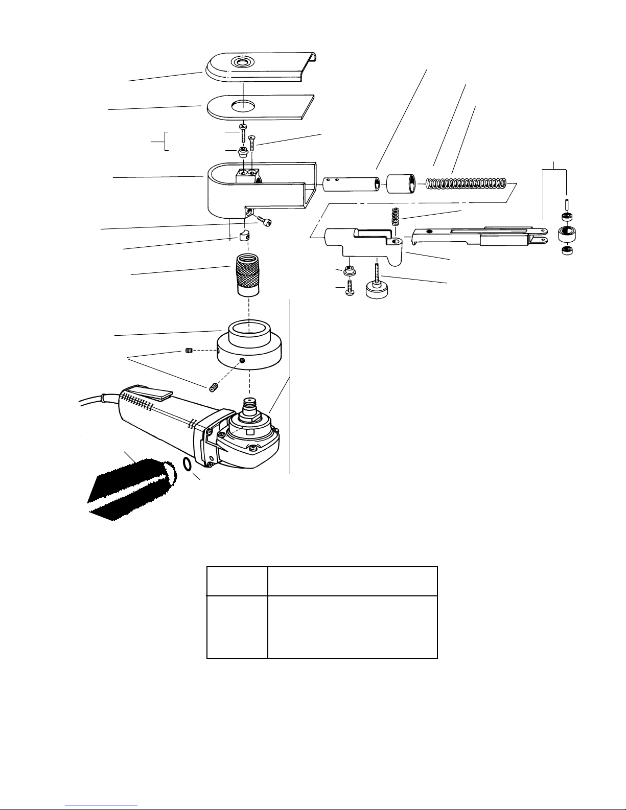
Head / Housing Assembly
40365 Belt Guard
(Incl. 40371 Gasket)
40371 Gasket
40360 Housing
95311 Screw
40029 Motor Lock
40520 Electric Motor only (See page 4 for Electric Motor Parts Breakdown)
40518 Electric Motor Assembly (Includes 40511 Drive Wheel, 40513 and
96110 Set Screws.)
*40511 Drive Wheel
*96110 Set Screws
Note: Shaded parts represent 40014 Housing Assembly.
95218 Knob
40361 Tension Arm
Contact Arm Assembly
For more information on Contact
Arm Assembly please refer to
chart on page 6.
95426 Spring
40367 Dust Cover
40362 Support Rod
11040 Spring
95217 Screw
40314 Button Latch Assy.
95425 Screw
40025 Button
95042 Washer
11535 Side Handle
Nameplate Extension Cord Length
Amperes 25' 50' 75' 100' 150' 200'
0-5 16 16 16 14 12 12
5.1-8 16 16 14 12 10 –
8.1-12 14 14 12 10 – –
12.1-15 12 12 10 10 – –
15.1-20 10 10 10 – – –
*Based on limiting the line voltage
drop to live volts at 150% of the
rated amperes
40366 Guide
95427 Screw
*40513 Adapter
Page 4

40520 Motor Assembly
4
To order replacement parts, specify model number and serial number of your machine.
1
2
10
11
16
17
20
21
18
22
23
24
36 26
(Incl. # 27, 36, 37, 38, 39)
37
27
25
38
39
29
30
31
35
15
12
14
13
32
33
34
19
(Incl.#20)
14
8
3
12428
5
9
6
FIG. PART NO. DESCRIPTION NO.REQ.
1 40567 Cord Protector (1)
2 40522 Cord Set (1)
3 40523 Service Nameplate Kit (1)
4 40524 Trigger (1)
5 40525 .146 Dia. x 1-3/8" Rivet (1)
6 40526 Motor Housing (1)
7 40527 O-Ring (2)
8 40528 Left Brush Holder (1)
9 40529 Switch (1)
10 40532 Cover (1)
11 40533 8-16 x 5/8" Pan Hd.
Slt. Plast.T-20 (3)
12 40534 Carbon Brush (2)
13 40535 Right Brush Holder (1)
14 40536 Brush Spring (2)
15 40537 Rubber Bumper (2)
16 40538 Rear Ball Bearing (1)
17 40539 120 V olt Field (1)
18 40540 8-16 x 2-1/2" Pan Hd.
Slt. Plast.T-20 (2)
19 40541 120 V olt Armature (1)
20 40542 Fan (1)
FIG. PART NO. DESCRIPTION NO.REQ.
21 40543 8-32 x3/8" Pan Hd.
Slt. Plast.T-20 (2)
22 40544 Front Ball Bearing (1)
23 40545 Pinion (1)
24 40546 1/4-28 Hex Lock Nut (1)
25 40548 8-16 x 5/8" Pan Hd.
Slt. Plast.T-20 (4)
26 40549 Gear Case Assembly (1)
27 40550 Needle Bearing (1)
28 40551 Coil Spring (1)
29 40553 Spiral Bevel Gear (1)
30 40554 Retaining Ring-Internal (1)
31 40555 Ball Bearing (1)
32 40557 Spindle Hub (1)
33 40558 8-32 x 1/2" Pan Hd.
Slt.T aptitet T-20 (4)
34 40559 Spindle (1)
35 40561 Shim (0-3)
36 40562 Cap (1)
37 40564 Coil Spring (1)
38 40565 O-Ring (1)
39 40566 Lock Pin (1)
7
Page 5

Dynafile®II Contact Arms
Optional 40078 Adapter allows use
of 24" long belts; extends reach to
7" when used with contact arm.
Arms for 4" to 17" workable reach.
45 PSI maximum.
Enter channels as
small as 7/16".
Belt Size: 1/2" W x 18" L.
Contact Wheel: 5/16" dia. x 3/8" W, rubber.
Platen:1/2" wide.
Work on broad areas, leaves
in-line scratch, blend stainless.
11200
11024 steel platen available.
6-3/4" workable reach.
11286
Belt Size: 1/2" W x 24" L.
Contact Wheel: 5/8" dia. x 3/8" W, rubber. Platen: 1/2" wide.
Grind on contact wheel
or platen; has 5-1/4"
workable reach.
11201
Belt Size: 1/2" W x 18" L.
Contact Wheel: 5/16" dia. x 3/8" W, steel.
Platen: 1/2" wide.
11202
Enter 5/16" x 3/4" openings.
Belt Size: 1/4" W x 18" L.
Contact Wheel: 5/8" dia. x 1/8" W, rubber.
Platen: 1/4" wide.
11287 — Uses 20-1/2" Belts
Belt Size: 5/8" or 3/4" W x 20-1/2" L
Contact Wheel: 3/4" dia. x 5/8" W, rubber. Platen: 3/4" wide.
11304 “The Banana Arm”
Work on broad areas;
leaves in-line scratch;
blend stainless.
Belt Size: 1/2" W x 18" L.
Contact Wheel: 5/8" dia. x 3/8" wide, rubber. Platen:1/2" wide.
2-1/2"
RUBBER
11322 Guide-Cut
Removes raised material within
.020" or less without undercutting.
GUIDE WHEELS
PREVENT
UNDERCUTTING
Belt Size: 1/2" W x 18" L. 60 to 80 grit.
Contact Wheel: 5/8" dia. x 3/8" W, rubber.
11329 Extra Length Arm
17" workable reach.
Belt Size: 1/2" W x 44" L.
Contact Wheel: 5/8" dia. x 3/8" W, rubber. Platen: 1/2" wide.
11350 “Bus Bar”
Excellent for cleaning oxide
off electrical bus bars. Arm
has a 12" workable reach.
Belt Size: 3/4" W x 34" L.
Contact Wheel: 5/16" dia. x 5/8" W, steel. Platen: 3/4" wide, optional.
11220, 11300, 11301, 11341
Polish T urbine Blades
Offset design and
miniature contact wheels.
2" strap polish in offset area;
polish turbine blades
and other contours.
11203* Order 11312 for heavy-duty version.
Grind over contact
wheel or platen.
Belt Size: 1/2" W x 18" L.
Contact Wheel: 5/8" dia. x 3/8" W, rubber. Platen: 1/2" wide.
11204 – “Unique Offset Design”
Strap polish is easy with this arm!
Belt Size: 1/4" or 1/2" W x 18" L.
Contact Wheel: 1" dia. x 3/8" W, rubber. Platen: None due to offset design.
11206
Belt Size: 5/8" or 3/4" W x 18" L.
Contact Wheel: 3/4" dia. x 5/8" wide, rubber. Platen:3/4" wide.
taperedStrap polish here
Order 11326 for Heavy Duty/Steel Construction version.
11280
Belt Sizes: 11220 uses 5/8" or 3/4" W x 18" L.
All others use 1/2" W x 18" L.
Contact wheels description for each above arm:
11220: 5/16" dia. x 5/8" W, steel. 11300: 1/4" dia. x 3/8" W, steel.
11301: 5/16" dia. x 3/8" W, steel. 11341: 5/16" dia. x 3/8" W, rubber.
Belt Size: 1/4" W x 18" L.
Contact Wheel: 1" dia. x 3/8" wide, urethane, tapered.
Platen: No platen due to offset design.
*Standard Contact Arm for Electric Dynafile® II.
Grind corners, enter
grooves, strap polish.
5
Page 6

6
Part Abrasive Contact Wheel Contact Wheel Contact Wheel Bearing
Number Belt Size Description Comments Assembly Only (2) Req. Shaft
11200 1/2" x 18" 5/8" Dia. x 3/8" W Rubber “Stroke-Sander Arm” 11088 (2) 11077 (2) 11052 (4) 11055 (2)
1/2" W Platen
11201 1/2" x 18" 5/16" Dia. x 3/8" W Steel 1/2" W Platen 11068 11067 11051 11054
11202 1/4" x 18" 5/8" Dia. x 1/8" W Rubber 1/4" W Platen 11074 11073 11052 11053
11203 1/2" x 18" 5/8" Dia. x 3/8" W Rubber 1/2" W Platen 11078 11077 11052 11054
11204 1/4" or 1/2" x 18" 1" Dia. x 3/8" Loose Belt Application 11080 11079 11052 11054
W Radiused Rubber
11206 5/8" or 3/4" x 18" 3/4" Dia. x 5/8" W Rubber 3/4" W Platen 11282 11281 11052 11285
11220 5/8" or 3/4" x 18" 5/16" Dia. x 5/8" W Steel Polish Turbine Blades 11352 11353 11051 11285
11280 1/4" x 18" 1" Dia. x 3/8" No Platen/Offset Design 11086 11085 11052 11054
W Tapered Urethane
11286 1/2" x 24" 5/8" Dia. x 3/8" W Rubber 1/2" W Platen 11078 11077 11052 11054
11287 5/8" or 3/4" x 20-1/2" 3/4" Dia. x 5/8" W Rubber 3/4" W Platen 11282 11281 11052 11285
11300 1/2" x 18" 1/4" Dia. x 3/8" W Steel Polish Turbine Blades 11332 11333 11334 11335
11301 1/2" x 18" 5/16" Dia. x 3/8" W Steel Polish Turbine Blades 11068 11067 11051 11054
11304 1/2" x 18" 5/8" Dia. x 3/8" W Rubber “Stroke-Sander Arm”-1/2" W Platen 11078 11077 11052 11054
11312 1/2" x 18" 5/8" Dia. x 3/8" W Rubber H.D. Version of 11203 Arm 11078 11077 11052 11054
11320 1/2" x 18" 5/8" Dia. x 3/8" W Rubber “Offset Arm” – prevent gouging. 11078 11077 11052 11054
11322 1/2" x 18" 5/8" Dia. x 3/8" W Rubber Contains two 11395 Guide 11090 11077 11052 95610
Wheels – Prevents Undercutting
11325 1/2" x 18" 5/8" Dia. x 3/8" W Rubber 1/2" W Steel Platen 11078 11077 11052 11054
11326 5/8" or 3/4" x 18" 3/4" Dia. x 5/8" W Rubber H.D. Version of 11206 Arm 11282 11281 11052 11285
11329 1/2" x 44" 5/8" Dia. x 3/8" W Rubber 1/2" W Platen/17" Reach 11078 11077 11052 11054
11341 1/2" x 18" 5/16" Dia. x 3/8" W Rubber Polish Turbine Blades 11342 11343 11334 11335
11350 3/4" x 34" 5/16" Dia. x 5/8" W Steel Bus Bar Arm/11" Reach 11352 11353 11051 11285
Dynafile®II Contact Arm Assembly Parts List
Contact Wheel Assembl y–Includes wheel, bearings and shaft.
Contact Arm
Shaft
Bearing
Contact Wheel
Bearing
Dynafile® II Standard Contact Arms
Page 7

Abrasive Belts
7
1/8" – 90211 90212 90143 90213 90214 90215 90216 90217
1/4" 90220 90221 90222 90144 90223 90224 90225 90226 90227
1/2" 90240 90241 90242 90145 90243 90244 90245 90246 90247
5/8" 90260 90261 90262 90146 90263 90264 90265 90266 90267
3/4" 90250 90251 90252 90147 90253 90254 90255 90256 90257
1" 90284 90285 90286 90148 90287 90288 90289 90290 90291
1/8" – 90405 90407 90408 90409 90410 90411 90412 90413
1/4" 90415 90417 90419 90420 90421 90423 90424 90425 90426
1/2" 90441 90443 90445 90446 90447 90449 90451 90453 90455
1" 90478 90482 90483 90491 90484 90486 90487 90488 90489
24" Long
18" Long
Abrasive Grit
40 60 80 100 120 180 220 320 500
Belt
Width
Coated Aluminum Oxide
Abrasive Grit
40 60 80 120
1/4" 91057 91058 91059 91048
1/2" 91066 91067 91068 91049
5/8" 91075 91076 91077 91050
3/4" 91084 91085 91086 91051
1" 91093 91094 91095 91052
1/4" 91111 91112 91113 91034
1/2" 91120 91121 91122 91035
18" Long
Belt
Width
24" Long
Ceramic Coated Aluminum Oxide
2" and Wider:50 Belts = Unit.
All Other Belts: 200 Belts = Unit.
Abrasive Grit
60 80 120
1/8" 94827 94828 94829
1/4" 94838 94839 94840
1/2" 94847 94848 94849
5/8" 94856 94857 94858
3/4" 94866 94867 94868
1" 94877 94878 94879
1/8" 90463 90464 90562
1/4" 90563 90564 90565
1/2" 90567 90568 90569
1" 90480 90481 90544
18" Long
24" Long
Belt
Width
200 Belts = Unit.
Coated Silicon Carbide
Abrasive Grit
60 80
1/4" 90166 90167
1/2" 90168 90169
5/8" 90170 90171
3/4" 90172 90173
1" 90177 90178
1/4" 90577 90582
1/2" 90579 90583
1" 90485 90474
24" Long
18" Long
Belt
Width
2" and Wider:50 Belts = Unit.
All Other Belts: 200 Belts = Unit.
Coated Alumina Zirconia
Part Number Use With
1/2" 90010 Dynafile® II Adapter
24" Long
Belt
Width
Cloth Polishing Belts
Grade
Super Fine Very Fine Medium Coarse
1/4" 90158 90228 90229 –
1/2" 90159 90248 90292 90297
5/8" 90160 90249 90293 90298
3/4" 90161 90258 90294 90299
1" 90162 90259 90295 90300
1/4" 90397 90403 90433 90460
1/2" 90398 90400 90434 90461
1" 90399 90402 90416 90462
Belt
Width
18" Long
1" and Wider:10 Belts = Unit. All Other Belts: 20 Belts = Unit.
Abrasive Impregnated Non-Woven Nylon
24" Long
Page 8

Abrasive Impregnated Non-Woven Nylon
Anon-woven synthetic fiber and an abrasive mineral are bonded together to
form a tough, open web that is chemically resistant and long-lasting. This
web design allows controlled conformable contact to workpiece contours,
corners and edges. The product wears away slowly, exposing new abrasive
leaving a uniform, consistent surface. It also conditions surfaces without
removing or damaging the base material and is excellent for deburring,
cleaning, blending and final finishing of metal, wood and plastics. It is
available in many forms such as belts, discs and wheels. Various mineral
grades are available ranging from very coarse to ultra-fine.
Cloth Polishing Belts
Used on power tools in conjunction with Dynuba® polishing compounds.
The result is brilliant cut, color and luster on metals such as stainless steel,
aluminum, copper and brass.
Coated Aluminum Oxide
The most widely used abrasive grain, this tough durable synthetic is used for
grinding and deburring high carbon steels, general metalworking and for
sanding certain hardwoods.
Ceramic Coated Aluminum Oxide
Synthetic grain two-to-three times tougher than conventional aluminum oxide.
Coated Silicon Carbide
Excellent for sanding primer and sealer, this sharp, fast-penetrating grain is
used for sanding soft materials such as glass, plastics and fibrous wood.
Coated Alumina Zirconia
Effective for coarse stock removal of metal and wood, this synthetic grain
has self-sharpening characteristics and provides continuous new cutting
edges for longer life and greater efficiency.
Abrasive Types and Cloth Polishing Belts
Dynapad®Platen Pads
Note: Dynapad Platen Pads are PSAmounted and easily trimmed to size.
Exceptions: 11024 and 11028 Steel Platens bolt on; 14341 clamps on. Unit = 10 packages each.
Part Pkg.
Number Used On Size Material Qty.
11024 Dynafile II (11286 Arm) 1/2" W x 3" L (bolts on) Steel 1
11025 Dynafile, Dynafile II 1/2" W x 7" Lx 1/8" Thk Soft/Sponge 5
11026 Dynafile, Dynafile II 1/2" W x 7" Lx 1/8" Thk Hard/ Cork 5
11027 Dynafile, Dynafile II 1/2" W x 7" Lx 1/32" Thk Thin 5
11028 Dynafile (11228 Arm) 1/2" W x 3" L (bolts on) Steel 1
11032 Dynafile 1/4" W x 7" L x 1/8" Thk Soft/ Sponge 5
11033 Dynafile 1/4" W x 7" L x 1/8" Thk Hard/ Cork 5
11034 Dynafile 1/4" W x 7" L x 1/32" Thk Thin 5
11109 Dynafile II 3/4" W x 7" L x 1/8" Thk Hard/ Cork 5
11119 Dynafile II 3/4" W x 7" L x 1/8" Thk Soft/ Sponge 5
11129 Dynafile II 3/4" W x 7" L x 1/32" Thk Thin 5
DYNABRADE
®
DYNABRADE, INC., 8989 Sheridan Drive • Clarence, NY 14031-1490 • Phone: (716) 631-0100 • Fax: 716-631-2073 • International Fax: 716-631-2524
DYNABRADE EUROPE s.a.r.l., Zone Artisanale • L-5485 Wormeldange—Haut, Luxembourg • Telephone: 352 76 84 94 • Fax: 352 76 84 95
©DYNABRADE, INC., 1995 PRINTED IN USA
 Loading...