

Page 1
SAFETY INSTRUCTIONS
Carefully Read all instructions before operating or servicing any Dynabrade®Abrasive Power Tool.
Products offered by Dynabrade are not to be modified, converted or otherwise alerted from the original design without expressed written consent from Dynabrade, Inc.
Tool Intent: Dynafile®abrasive belt machine replaces tedious hand filing and sanding and can be used for grinding, deburring, blending and polishing. Can be used on most
materials including metal, plastic, fiberglass, composites, rubber, glass and stone.
Do Not Use Tool For Anything Other Than Its Intended Applications.
Training: Proper care, maintenance, and storage of your tool will maximize its performance.
• Employer's Responsibility – Provide Dynafile®operators with safety instructions and training for safe use of tools and accessories.
Accessory Selection:
• Abrasive/accessory RPM (speed) rating MUST be approved for AT LEAST the tool RPM rating.
• Before mounting an accessory, visually inspect for defects. Do not use defective accessories.
• Mount only recommended accessories. See back page of manual and Dynabrade catalog.
• Follow tool specifications before choosing size and type of accessory.
• Only use recommended fittings and air line sizes. (See tool Machine Specifications table.)
OPERATING INSTRUCTIONS
Warning: Always wear eye protection. Operator of tool is responsible for following: accepted eye, face, respiratory, hearing and body protection.
Caution: Hand, wrist and arm injury may result from repetitive work, motion and overexposure to vibration.
(continued on next page)
Parts Page Reorder No. PD02•01R
Effective January, 2002
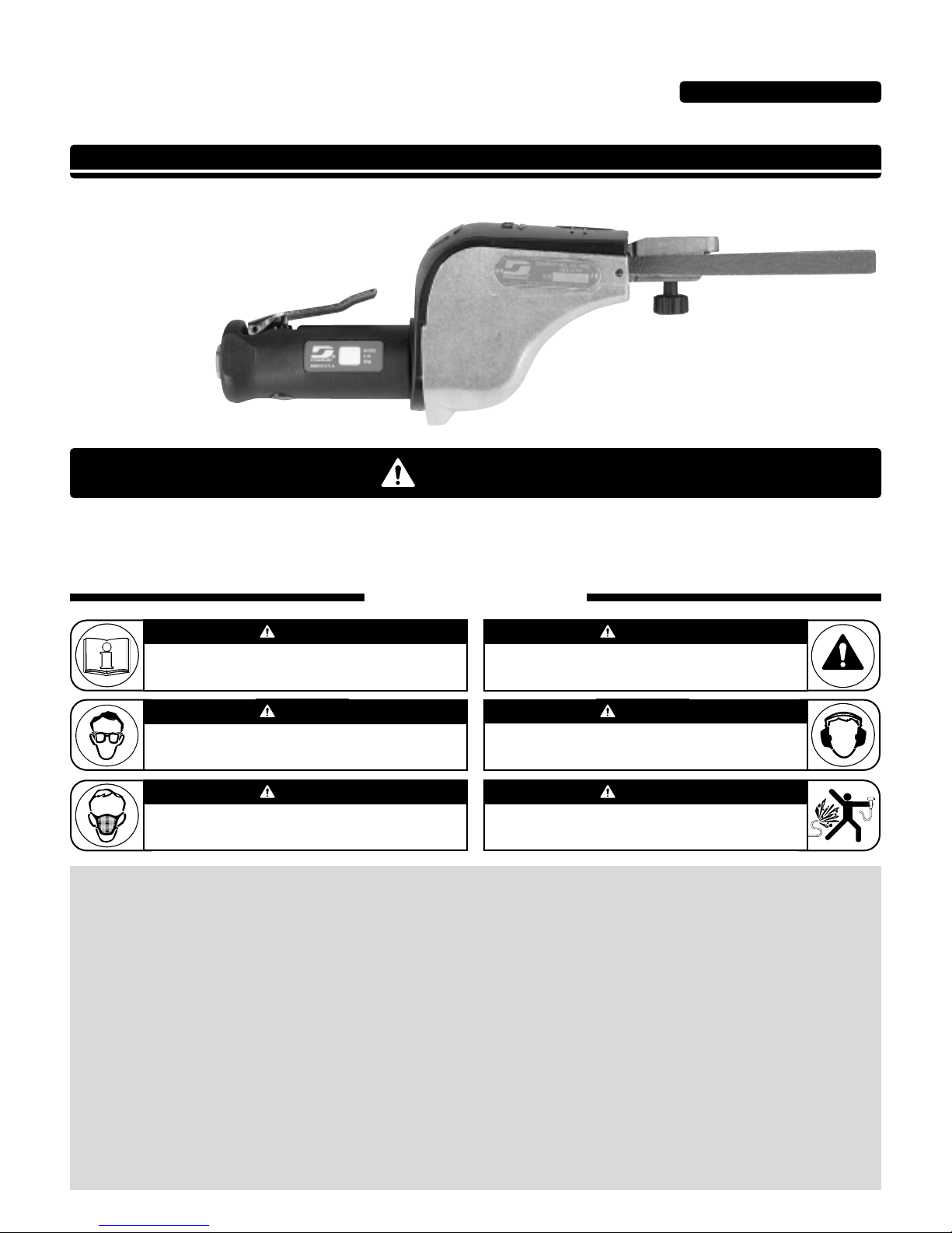
Dynafile
®
Air Tool Manual – Safety, Operation and Maintenance
Models:
14000 – 20,000 RPM
14010 – Versatility Kit
SAFETY LEGEND
G
Read and understand tool manual before
work starts to reduce risk of injury to
operator, visitors, and tool.
Eye protection must be worn at all times,
eye protection to conform to ANSI Z87.1.
Respiratory protection to be used when exposed to
contaminants that exceed the applicable threshold
limit values required by law.
Practice safety requirements.Work alert,
have proper attire, and do not operate tools under
the influence of alcohol or drugs.
Ear protection to be worn when exposure to sound,
exceeds the limits of applicable Federal, State or
local statues, ordinances and/or regulations.
Air line hazard, pressurized supply lines and flexible
hoses can cause serious injury.Do not use damaged,
frayed or deteriorated air hoses and fittings.
Read and understand this tool manual before operating your air tool.Follow all safety rules for the protection of operating personnel
as well as adjacent areas. Always operate, inspect and maintain this tool in accordance with the American National Safety Institute
(ANSI) Safety Code for Portable Air Tools – B186.1.For additional safety information, refer to Safety Requirements for the Use, Care
and Protection of Abrasive Wheels – ANSI B7.1, Code of Federal Regulation – CFR 29 Part 1910, European Committee for Standards
(EN) Hand Held Non-Electric Power Tools – Safety Requirements and applicable State and Local Regulations.
SAVE THIS DOCUMENT, EDUCATE ALL PERSONNEL
For Serial No. 2C1000 and Higher
WARNIN
WARNING
WARNING
WARNING
WARNING
WARNING
WARNING
Page 2
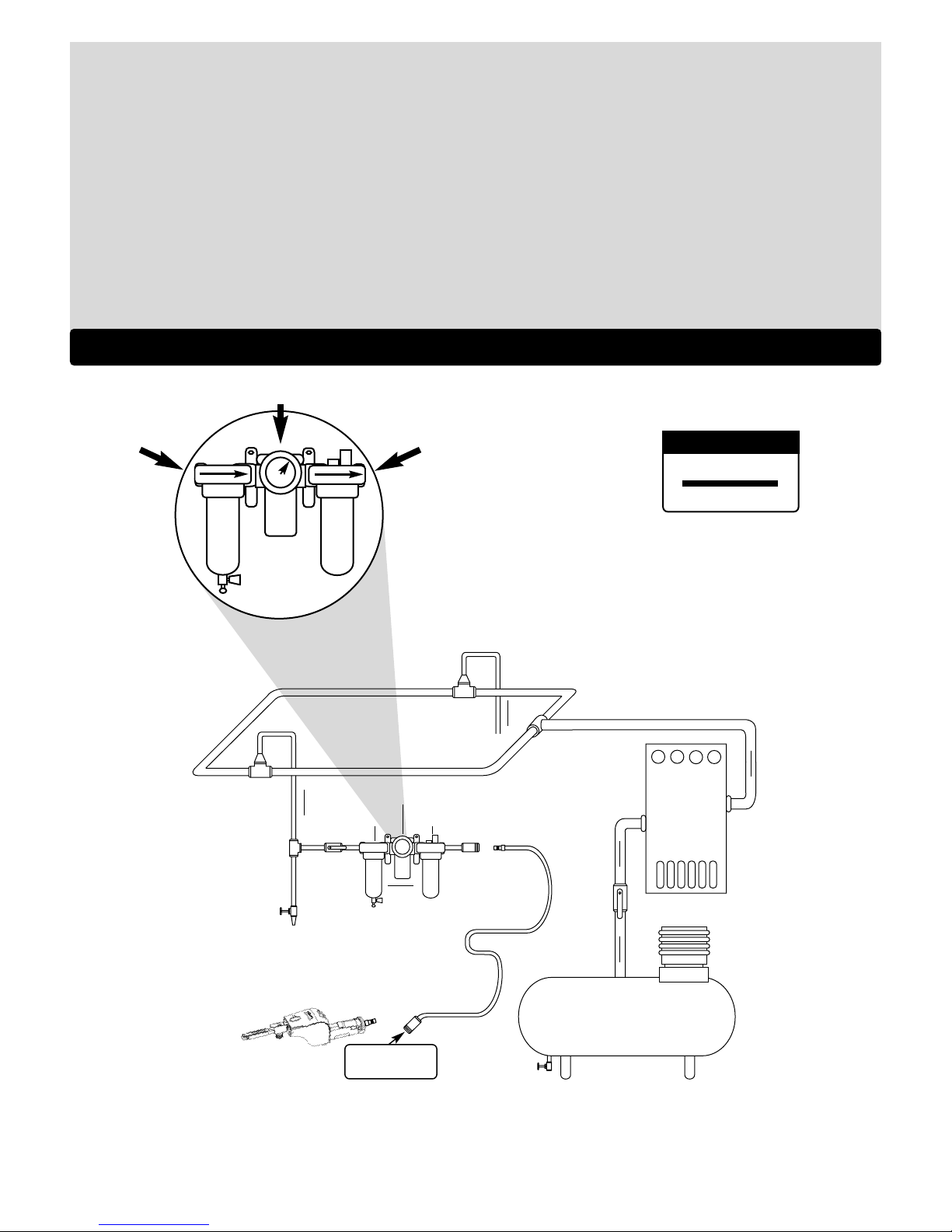
To Tool Station
Closed Loop Pipe System
Ball
Valve
Ball
Valve
Filter
Regulator
Lubricator
Air Flow
Drain
Valve
Drain
Valve
Air Tool
Air Compressor
and Receiver
Drain
Valve
Air Hose
90 PSIG MAX
(6.2 Bar)
Air Flow
Refrigerated
Air Dryer
2
Filter
Regulator
Lubricator
90 PSIG
(6.2 Bar)
OPERATING INSTRUCTIONS (continued)
• Keep hand and clothing away from working end of the air tool.
Operation: Be sure that any loose clothing, hair and all jewelry is properly restrained.
• Secure inlet bushing on air tool with a wrench before attempting to install the air fitting to avoid damaging housing assembly.
• Check tool RPM (speed) with tachometer with air pressure set at 90 PSIG while the tool is running. If tool is operating at a higher speed than the RPM marked on the tool
housing, or operating improperly, the tool must be serviced and corrected before use.
Caution: Tool RPM must never exceed abrasive/accessory RPM rating. Check accessory manufacturer for details on maximum operating speed or special
mounting instructions.
• Disconnect air hose from tool when changing belts and contact arms.
• Connect air tool to power source. Be careful NOT to depress throttle lever in the process. Do not expose air tool to inlet pressure above 90 PSIG or (6.2 Bars).
Caution: After installing the accessory, before testing or use and/or after assembling tool, the Dynafile®must be started at a reduced speed to check for good balance.
Gradually increase tool speed. DO NOT USE if tool vibration is excessive. Correct cause, and retest to insure safe operation.
• Make sure that work area is uncluttered, and visitors are at a safe range from the tools and debris.
• Use a vise or clamping device to hold work piece firmly in place.
• Do not apply excessive force on tool or apply “rough” treatment to it.
• Always work with a firm footing, posture and proper lighting.
Report to your supervisor any condition of the tool, accessories, or operation you consider unsafe.
Air System
1 DROP/MIN.
10 SCFM
LUBRICATOR SETTING
• Ideally the air supply should be free from moisture.
Incorporating a refrigerated air dryer after the
compressor and drain valves at each tool station
(as shown) further reduces moisture from
condensation in the air supply.
• Dynabrade Air Power Tools are designed to
operate at 90 PSIG (6.2 Bar/620 kPa) maximum
air pressure at the tool inlet, when the tool is
running. Use recommended regulator to control
air pressure.
➤
➤
➤
➤
➤
➤
Page 3

Maintenance Instructions
Important: A Preventative Maintenance Program is recommended whenever portable power tools are used.
• Use only genuine Dynabrade replacement parts to insure quality. To order replacement parts, specify Model #, Serial # and RPM
of your air tool.
• It is strongly recommended that all Dynabrade rotary vane air tools be used with a Filter-Regulator-Lubricator to minimize the possibility
fo misuse due to unclean air, wet air or insufficient lubrication. Dynabrade recommends the following: 11405 Air Filter-Regulator-
Lubricator (FRL) – Provides accurate air pressure regulation and two stage filtration of water contaminants. Operates 40 SCFM/1,133
LPM @ 100 PSIG with 3/8" NPT female ports.
• Dynabrade recommends one drop of air lube per minute for each 10 SCFM (example: if the tool specification states 40 SCFM, set the
drip rate on the filter-lubricator to 4 drops per minute). Dynabrade Air Lube (P/N 95842: 1 pt 473 ml) is recommended.
Routine Preventative Maintenance: Check free speed of Dynafile®using a tachometer.
• Mineral spirits are recommended when cleaning the tool and parts. Do not clean tool or parts with any solvents or oils containing acids,
esters, ketones, chlorinated hydrocarbons or nitro carbons.
• DO NOT clean or maintain tools with chemicals that have a low flash point (example: WD-40®).
• A Motor Tune-Up Kit (P/N 95600) is available which includes high wear and medium wear motor parts.
• Air tool labels must be kept legible at all times, if not, reorder label(s) and replace. User is responsible for maintaining specification
information i.e.: Model #, S/N, and RPM. (See Assembly Breakdown)
• Blow air supply hose out prior to initial use.
• Visually inspect air hoses and fittings for frays, visible damage and signs of deterioration. Replace damaged or worn components.
• Refer to Dynabrade's Warning/Safety Operating Instructions Tag (Reorder No. 95903) for safety information.
After maintenance is performed on tool, add a few drops of Dynabrade Air Lube (P/N 95842) to the air line and start the tool a few times to
lubricate air motor. Check for excessive tool vibration.
Handling and Storage:
• Use of tool rests, hangers and/or balancers is recommended.
• Protect tool inlet from debris (see Notice below).
• DO
NOT carry tool by air hose.
• Protect abrasive accessories from exposure to water, solvents, high humidity, freezing temperature and extreme temperature changes.
• Store accessories in protective racks or compartments to prevent damage.
Notice
All Dynabrade motors use the highest quality parts and metals available and are machined to exacting tolerances. The failure of quality
pneumatic motors can most often be traced to an unclean air supply or the lack of lubrication. Air pressure easily forces dirt or water
contained in the air supply into motor bearings causing early failure. It often scores the cylinder walls and the rotor blades resulting in limited
efficiency and power. Our warranty obligation is contingent upon proper use of our tools and cannot apply to equipment which has been
subjected to misuse such as unclean air, wet air or a lack of lubrication during the use of this tool.
One Y ear Warranty
Following the reasonable assumption that any inherent defect which might prevail in a product will become apparent to the user within one
year from the date of purchase, all equipment of our manufacture is warranted against defects in workmanship and materials under normal
use and service. We shall repair or replace at our factory, any equipment or part thereof which shall, within one year after delivery to the
original purchaser, indicate upon our examination to have been defective. Our obligation is contingent upon proper use of Dynabrade tools in
accordance with factory recommendations, instructions and safety practices. It shall not apply to equipment which has been subject to
misuse, negligence, accident or tampering in any way so as to affect its normal performance. Normally wearable parts such as bearings,
contact wheels, rotor blades, etc., are not covered under this warranty.
Machine Specifications
3
Model Motor Motor Sound Abrasive Belt Size Maximum Air Flow Max. SFPM Weight Length Height
Number HP (W) RPM Level Inch (mm) CFM/SCFM (LPM) (SMPM) Pound (kg) Inch (mm) Inch (mm)
All Models .5 (373) 20,000 77 dB(A) 1/8-1/2 (3-13) W x 24 (610) L 4/31 (878) 5,800 (1,762) 3.1 (1.4) 14.6 (371) 4.0 (115)
Additional Specifications: Air Inlet Thread 1/4" NPT • Hose I.D. Size 3/8" (10mm) • Air Pressure 90 PSIG (6.2 Bars)
(PD02•01R)
Page 4
Dynafile
®
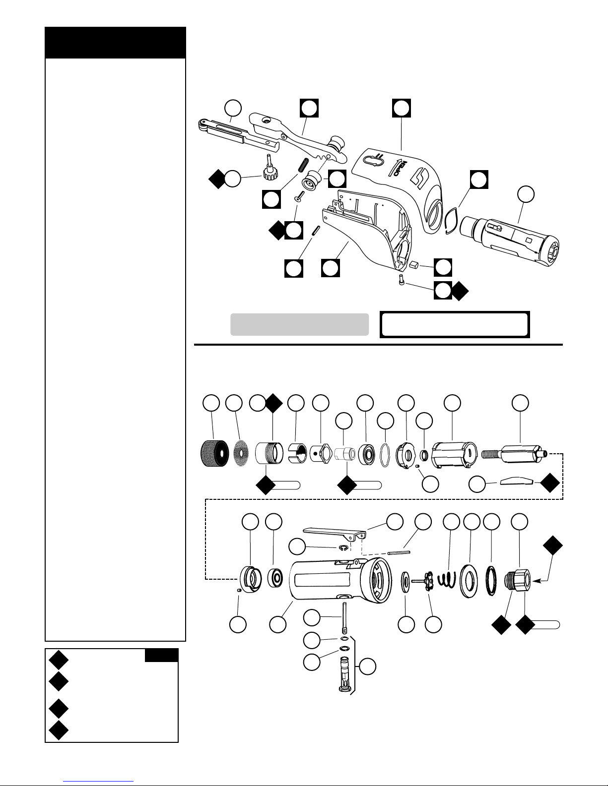
Complete Assembly Breakdown
4
01197 Air Motor with 01111 Drive Wheel
Note: 50971 Lock Ring Wrench is available for removal/installation of 04087 Lock Ring.
See inside for Important Operating, Maintenance and Safety Instructions before operating tool.
1 Contact Arm Assembly
(See pages 8-11)
2 95218 Knob Assembly
3* 11420 Idler Arm Assy., Includes:
95070 Threaded Insert
11040 Spring
4 11359 Tension Spring
5* 95162 Screw (2)
6* 11011 Idler Wheel Assy. (2) Includes:
95162 Screw
11013 Bearing
11006 Idler Wheel
7 95216 Pivot Pin
8 11418 Housing
9 95168 Screw
10 40029 Motor Lock
11 11419 Cover
12 11424 Wave Spring
13 01197 Air Motor
14 0 1111 Drive Wheel
15 10295 Screen
16 04087 Lock Ring
17 04078 Felt Silencer
18 04084 Air Control Ring
19 04081 Rotor Nut
20 01007 Bearing
21 01121 Shim Pack (3/pkg.)
22 01008 Bearing Plate
23 50767 Pin (2)
24 01010 Rotor Spacer
25 01013 Cylinder
26 01011 Blade (4) (4/pkg.)
27 01120 Rotor
28 01244 Bearing Plate
29 01015 Bearing
30 95558 Retaining Ring
31 30420 Housing
32 01477 Valve Stem
33 95730 O-Ring
34 01024 O-Ring
35 01247 Speed Regulator Assembly
36 01090 Throttle Lever
01089 Safety Throttle Lever
37 01017 Pin
38 01464 Seal
39 01472 Tip Valve
40 01438 Spring
41 53190 Block Plate
42 96065 O-Ring
43 01494 Inlet Adapter
Index Key
No. Part # Description
T
G
A
O
Adhesive: A
3
= Loctite #242
A
8
= Loctite #567
Torque: N•m x 8.85 = In. - lbs.
KEY
14
10
12
11
8
6*
1
3*
13
15 17 18
19
20 22 25 27
26
23
28 29
30
36 37 40 41 42 43
393823
32
33
34
35
21 24
23 N•m
T
17 N•m
T
23 N•m
T
O
1
O
1
A
8
G
2
G
2
A
3
A
8
Oil: O1= Air Lube
Grease: G
2
= Loctite #771
31
16
9
2
*Indicates individual parts that are
included in 11421 Idler Arm Assembly
Note: All Boxed index numbers represent
11431 Housing Assembly.
5*
4
7
Page 5

Disassembly/Assembly Instructions - Dynafile
®
Important: Manufacturer’s warranty is void if tool is disassembled before warranty expires.
Notice: A complete Tune-Up Kit, part number 95600, is available which includes assorted parts to help maintain motor in peak condition.
Please refer to parts breakdown for part identification.
Disconnect tool from power source before tool repair.
To Disassemble:
1. Disconnect the tool from air supply.
2. Secure the 11418 Housing in a padded vise.
3. Use a 9/64" hex key to loosen 95168 Screw and to remove the 01197 Air Motor, 11424 Wave Spring, and 11419 Cover.
4. To remove the 11421 Idler Arm Assembly use a 1/8" dia. punch and drive out the 95216 Pivot Pin.
Motor Disassembly:
1. Hold the 01197 Air Motor in a soft jaw (aluminum or bronze) vise securing it at the flats near the inlet area of the housing.
2. To remove the 0 1111 Drive Wheel insert a 3/16" hex key through the center of the drive wheel and into the 01120 Rotor.
3. Hold the drive wheel with pliers or pipe wrench and turn the 01111 Drive Wheel counter-clockwise to remove.
4. Use an adjustable pin wrench or 50971 Lock Ring Wrench to remove the 04087 Lock Ring by turning it counter-clockwise. Remove the 04078 Felt
Silencer and air control ring.
5. The motor assembly can be pulled out of the motor housing.
6. Fasten a 2" bearing separator around the portion of the 01013 Cylinder closest to the rear bearing/bearing plate assembly. Place the separator and
motor on the table of an arbor press so that the threaded rotor shaft points toward the floor.
7. Use a 3/16" dia. drive punch and press the rear shaft of the rotor out of the 01015 Rear Motor Bearing.
8. Remove the 01015 Bearing with 96211 Bearing Removal Tool and an arbor press.
9. Hold the vane portion of the rotor in a soft jaw (aluminum or bronze) vise and turn the 04081 Rotor Nut counter-clockwise.
10. The 01007 Bearing, 01008 Front Bearing Plate, 01121 Shims, and 01010 Spacer can now be removed from the 01120 Rotor.
Motor Disassembly Complete.
Valve Body Disassembly:
1. Position the flats of the 30420 Housing in a soft jaw (aluminum or bronze) vise with the air inlet pointing up.
2. Hold the 01494 Inlet Adapter stationary with a wrench and remove any air fitting. Important: The 01494 Inlet Adapter must be held securely to prevent
damage to the 30420 Housing.
3. Remove 01494 Inlet Adapter to access the 01438 Spring, 01472 Tip Valve, and 01464 Seal.
4. Use a 2.5mm drive punch punch to remove 01017 Pin and the throttle lever.
5. The 01477 Valve Stem can be pulled out of the 01247 Speed Regulator Assembly.
6. Use retaining ring pliers to remove the 95558 Retaining Ring and then push 01247 Speed Regulator Assembly out of the 30420 Housing.
Disassembly Complete.
Motor Assembly:
Important: Be sure parts are clean and in good repair before assembling.
1. Place 01120 Rotor in an aluminum or bronze jaw vise with a threaded spindle pointing upwards.
2. Slip 01010 Spacer onto rotor.
3. Place a .002" shim into front bearing plate as an initial spacing and slip 01007 Bearing into plate.
Note: 01121 Shim Pack contains .001" and .002" shims.
4. Install bearing/bearing plate assembly onto rotor.
5. Install 04081 Rotor Nut onto assembly.
6. Tighten rotor nut onto rotor (torque to 17 N•m/150 in. - lbs.).
7. Check clearance between rotor and bearing plate by using a .001" feeler gauge. Clearance should be at .001" to .0015". Adjust clearance by repeating
steps 1-4 with different shim if necessary.
8. Once proper rotor/gap clearance is achieved, install well lubricated 01011 Blades (4) into rotor slots. Dynabrade air lube P/N 95842 is
recommended for lubrication.
9. Install cylinder over rotor. Be sure air inlet holes of cylinder face away from bearing plate.
10. Press 01015 Rear Bearing into 01244 Rear Bearing Plate. Press bearing/bearing plate assembly onto rotor (96241 Bearing Press Tool is available). Be
sure that pin and air inlet holes line-up with pin slot and air inlet holes in cylinder.
Important: Fit must be snug between bearing plates and cylinder. If too tight, rotor will not turn freely. Rotor must then be lightly tapped at press fit
end so it will turn freely while still maintaining a snug fit. A loose fit will not achieve the proper preload of motor bearings.
11. Secure motor housing in padded vise so motor cavity faces upwards.
12. Install motor assembly into housing, making sure motor drops all the way into housing.
Note: Align the rear bearing plate node with the notch inside the housing.
13. Insert air control ring and 04078 Felt Silencer into 04087 Lock Ring and install onto motor housing (torque 23 N•m/200 in. - lbs.).
14. Motor adjustment must now be checked. With motor housing still mounted in vise, pull end of rotor and twist (10-15 lbs. force), rotor should turn
freely without drag. If drag or rub is felt, then increase preload or remove shim. Also, push end of rotor and twist (10-15 lbs. force), rotor should
turn freely without drag. If drag or rub is felt, then deload or add shim.
15. Install 10295 Screen and 01111 Drive Wheel.
(continued on next page)
5
Page 6

Disassembly/Assembly Instructions - Dynafile
®
(continued)
16. Place 11418 Housing in a padded vise, slip 11424 Wave Spring, then 11419 Cover over the lock ring on the motor and install 01197 Motor to housing.
17. Tighten 95168 Screw with 9/64" allen wrench.
18. Install 11359 Tension Spring, 11421 Idler Arm Assembly, and 95216 Pivot Pin. Important: Use 1/8" diameter drive pin punch to line-up 11421 Idler Arm
Assembly with 11418 Housing.
19. Install 11419 Cover, contact arm assembly and abrasive belt.
Valve Body Assembly:
1. Insert 01247 Speed Regulator Assembly with o-rings into valve body. Secure with 95558 Retaining Ring.
2. Secure valve body in padded vise with air inlet point up.
3. Insert 01464 Seal into housing.
4. Line up hole in valve stem with hole in housing (looking past brass bushing). Insert 01472 Tip Valve so that the metal pin passes through the hole in the
valve stem. Install 01438 Spring (small end towards tip valve).
5. Install 53190 Block Plate along with 96065 O-Ring into housing.
6. Apply Loctite #567 PST Pipe Sealant to threads of 01494 Inlet Adapter and install into valve body (torque 23 N•m/ 200 in. - lbs.).
7. Install throttle lever and 01017 Pin.
Tool Assembly Complete. Please allow 30 minutes for adhesives to cure before operating tool.
Important: Motor should now be tested for proper operation at 90 PSIG. If motor does not operate properly or operates at a higher RPM than marked on
the tool, the tool should be serviced to correct the cause before use. Before operating, place 2-3 drops of Dynabrade Air Lube (P/N 95842) directly into air
inlet with throttle lever depressed. Operate tool for 30 seconds to determine if tool is operating properly and to allow lubricating oils to properly penetrate motor
Loctite®is a registered trademark of Loctite Corp.
Abrasive Belt Change and Removal:
To Remove Belt:
1. Open 11419 Cover.
2. Depress idler arm lever and pull belt away from the contact wheel.
3. Slip belt off drive wheel.
To Replace Belt:
1. Create a loop with belt by pinching together the sides of belt in the middle.
2. Slip one loop under the 01111 Drive Wheel and around the idler arm.
3. Depress idler arm lever and pull belt toward the contact wheel.
4. Slip belt over contact wheel.
5. Connect tool to power source.
6. Adjust belt tracking using 95218 Knob.
14000
Dynafile
®
Safety Throttle
Lever (Optional)
Idler Arm
Assembly
Speed
Control
Screw
Air Motor Drive
Wheel
Wave
Spring
Idler Wheel
Assembly
Tracking
Adjustment Knob
Idler Arm Contact
Arm Assembly
(See pages 8-11)
6
01089 11421 11011 11420 11218
9521801111
Housing
11418114240119701247
Page 7

This service chart is published as a guide to expectant life of component parts. The replacement levels are based on average tool
usage over one year. Dynabrade Inc. considers one year usage to be 1,000 hours or 50% of a man year. Parts included in motor
tune-up kit are identified by High Wear and Medium Wear items.
Parts Common to all Models:
Preventative Maintenance Schedule
For All Dynafile
®
LEGEND
X Type of wear, no other
comments apply.
L Easily lost. Care during
assembly/disassembly.
D Easily damaged.during
assembly/disassembly.
R1 Replace each time tool is
disassembled.
R2 Replace each second
time tool is disassembled.
Note: Please refer to pages 8-10 of tool manual for specific part number.
Index Part Description Number High Wear Medium Wear Low Wear Non-Wear
# Number Required 100% 70% 30% 10%
1 See Note Contact Arm Assembly 1
2
95218 Knob Assembly 1 X
3 11420 Idler Arm 1 X
(Incl. 95070 Threaded Insert)
4 11359 Tension Spring 1 X
5 95162 Screw 2 X
6 11011 Idler Wheel Assembly 2 X
(Incl. 95162 Screw, 11013
Bearing & 11006 Idler Wheel)
7 95216 Pivot Pin 1 X
8 11418 Housing 1 X
9 95168 Screw 1 X
10 40029 Motor Lock 1 L
11 11419 Cover 1 X
12 11424 Wave Spring 1 X
13 01197 Air Motor 1 X
14 01111 Drive Wheel 1 X
15 10295 Screen 1 L
16 04087 Lock Ring 1 X
17 04078 Felt Silencer 2 X
18 04084 Air Control Ring 1 X
19 04081 Rotor Nut 1 X
20 01007 Bearing 1 X
21 01121 Shim Pack (3/pkg.) 1 D
22 01008 Bearing Plate 1 X
23 50767 Pin 1 X
24
01010 Rotor Spacer
1
X
25 01013 Cylinder 1 X
26 01011 Blade (4/pkg.) 1 X
27 01120 Rotor 2 X
28 01244 Bearing Plate 1 X
29 01015 Bearing 1 X
30 95558 Retaining Ring 1 D
31 30420 Housing 1 X
32 01477 Valve Stem 2 X
33 95730 O-Ring 1 X
34 01024 O-Ring 1 X
35 01247 Speed Regulator Assembly 1 X
36 01090 Throttle Lever 1 X
01089 Safety Throttle Lever 1 X
37 01017 Pin 1 X
38 01464 Seal 1 X
39 01472 Tip Valve 1 X
40 01438 Spring 1 L
41 53190 Block Plate 1 X
42 96065 O-Ring 1 L
43 01494 Inlet Adapter 1 X
7
95600 – Motor Tune-Up Kit
•
Tune-Up Kit includes high wear
and medium wear motor parts.
Page 8

Part Abrasive Contact Wheel Contact Wheel Contact Wheel Bearing
Number Belt Size Description Comments Assembly Only (2) Req. Shaft
11178 1/2" x 34" 5/16" Dia. x 3/8" W Steel 9" Reach 11068 11067 11051 11054
11179 1/2" x 34" 5/8" Dia. x 3/8" W Rubber 9" Reach 11078 11077 11052 11054
11212 1/4" x 24" 5/16" Dia. x 1/8" W Steel 1/4" W Platen 11066 11065 11051 (1) 11056
11213 1/2" x 24" 5/16" Dia. x 3/8" W Steel 1/2" W Platen 11068 11067 11051 11054
11214 1/2" x 24" 7/16" Dia. x 3/8" W Rubber 1/2" W Platen 11070 11069 11051 11054
11215 1/4" x 24" 7/16" Dia. x 1/8" W Brass 1/4" W Platen 11072 11071 11052 (1) 11053
11216 1/4" x 24" 5/8" Dia. x 1/8" W Rubber 1/4" W Platen 11074 11073 11052 (1) 11053
11217 1/2" x 24" 1/2" Dia. x 3/8" W Steel 1/2" W Platen 11076 11075 11052 11054
11218 1/2" x 24" 5/8" Dia. x 3/8" W Rubber 1/2" W Platen 11078 11077 11052 11054
11219 1/4" or 1/2" x 24" 1" Dia. x 3/8" W Radiused Rubber No Platen 11080 11079 11052 11054
11228 1/2" x 24" 5/8" Dia. x 3/8" W Rubber H.D. Version of 11218 Arm 11078 11077 11052 11054
11231 1/2" x 24" 3/4" Dia. x 1/2" W Rubber 1/2" W Platen 11084 11083 11052 11055
11232 1/8" or 1/4" x 24" 1" Dia. x 3/8" W Tapered Urethane No Platen 11086 11085 11052 11054
11234 1/2" x 34" 1" Dia. x 3/8" W Radiused Rubber Double Burrer Arm 11080 (2) 11079 (2) 11052 N/A
11237 5/16" x 24" 5/16" Dia. x 1/8" W Steel Polish Turbine Blades 11066 11065 11051 (1) 11053
11238 1/2" x 24" 1/4" Dia. x 3/8" W Steel Polish Turbine Blades 11051 (3) and 11054 11051 (3) N/A 11054
11239 1/2" x 24" 5/16" Dia. x 3/8" W Steel H.D. Version of 11213 Arm 11068 11067 11051 11054
11240 1/2" x 34" 5/8" Dia. x 3/8" W Rubber 1/2" W Platen - 9" Reach 11078 11077 11052 11054
11241 1/4" x 34" 5/8" Dia. x 1/8" W Rubber 1/4" W Platen - 9" Reach 11074 11073 11052 (1) 11053
11243 1/2" x 24' 3/4" Dia x 1/2" W Rubber H.D. Version of 11231 Arm 11084 11083 11052 11055
11244 1/2" x 44" 5/8" Dia. x 3/8" W Rubber 1/2" W Platen - 14" Reach 11078 11077 11052 11054
11245 1/4" x 44" 5/8" Dia. x 1/8" W Rubber 1/4" W Platen - 14" Reach 11074 11073 11052 (1) 11053
11254 1/2" or 1/4" x 34" 4-3/4" or 2-1/8" Dia. to 1/4" or 1/2" W Grind in Deep Narrow Slots Variable Variable 11013 (1) 95162
11255 1/2" x 34" 5/8" Dia. x 3/8" W Rubber Deburr I.D. 1" to 4" 11078 11077 11052 11054
11257 1/2" Wide 5/16" Dia. x 3/8" W Steel or 5/8" Dia. x 3/8" W Rubber “Spear-Arm” - Specify length up to 32" 11068 Steel 11067 Steel 11051 Steel 11054
11078 Rubber 11077 Rubber 11052 Rubber
11258 1/2" x 24" 1/2" Dia. x 3/8" W Steel and 5/8" Dia. x 3/8" W Rubber Platen Between 2 Contact Wheels 11076 Steel 11075 Steel 11052 (4) 11054 (2)
11078 Rubber 11077 Rubber
11261 1/2" x 24" 5/8" Dia. x 3/8" W Rubber “Banana Arm” – For in-line scratch pattern. 11078 11077 11052 11054
11262 1/2" x 24" 5/8" Dia. x 3/8" W Rubber “Offset Arm” – Contact wheel is offset to prevent gouging. 11078 11077 11052 11054
11297 1/2" x 24" 5/8" Dia. x 3/8" W Rubber Contains two 11395 Guide Wheels. Prevents undercutting. 11090 11077 11052 95610
Dynafile®Standard Contact Arm Assemblies
11288 Dynafile Contact Arm and Idler Wheel Repair Kit
• Contains special tools to assist in the replacement
of contact wheels and bearings.
See next page for a complete guide to contact arms. Also see page 11 for contact arm disassembly and assembly instructions.
Page 9

Belt Size: 1/4" W x 24" L.
11066 Contact Wheel: 5/16" diameter x 1/8" wide, steel.
11034 Platen: 1/4" wide.
11212 File round openings as small as 7/16".
45 PSIG maximum.
Belt Size: 1/2" W x 24" L.
11068 Contact Wheel: 5/16" diameter x 3/8" wide, steel.
11027 Platen: 1/2" wide.
11213 See 11239 for heavy-duty version.
45 PSIG maximum.
Belt Size: 1/2" W x 24" L.
11070 Contact Wheel: 7/16" diameter x 3/8" wide, rubber.
11025 Platen: 1/2" wide.
11214 Work on contact wheel or Dynapad
®
.
45 PSIG maximum.
Belt Size: 1/4" W x 24" L.
11072 Contact Wheel: 7/16" diameter x 1/8" wide, brass.
11034 Platen: 1/4" wide.
11215 Enter 1/2" x 1/2" openings.
Belt Size: 1/4" W x 24" L.
11074 Contact Wheel: 5/8" diameter x 1/8" wide, rubber.
11032 Platen: 1/4" wide.
11216 Enter 5/16" x 3/4" openings.
Belt Size: 1/2" W x 24" L.
11076 Contact Wheel: 7/16" diameter x 3/8" wide, steel.
11027 Platen: 1/2" wide.
11217 Enter channels as narrow as 9/16".
11218 Standard arm on model 14000.
See 11228 for heavy-duty version.
Dynafile®Standard Contact Arms
Standard Contact Arms allow for a 4" workable reach.
9
Belt Size: 1/2" W x 24" L.
11078 Contact Wheel: 5/8" diameter x 3/8" wide, rubber.
11025 Platen: 1/2" wide.
Belt Size: 1/4" or 1/2" W x 24" L.
11080 Contact Wheel: 1" diameter x 3/8" wide, radiused rubber.
No Platen
11219 No platen due to offset design.
Grind radiuses, slack polish.
Offset for slack polishing
Belt Size: 1/2" W x 24" L.
11078 Contact Wheel: 5/8" diameter x 3/8" wide, rubber.
11025 Platen: 1/2" wide.
11228 Heavy-Duty Steel Optional 11028 Steel Platen
available for grinding.
Belt Size: 1/2" W x 24" L.
11084 Contact Wheel: 3/4" diameter x 1/2" wide, rubber.
11135 Platen: 1/2" wide.
11231 See 11243 for heavy-duty version.
Belt Size: 1/8" or 1/4" W x 24" L.
11086 Contact Wheel: 1" diameter x 3/8" wide, tapered urethane.
No Platen.
11232 For 1/8" Wide Belts No platen due to offset design.
Grind corners, strap polish.
V-Tapered
Belt Size: 1/2" W x 24" L.
11068 Contact Wheel: 5/16" diameter x 3/8" wide, steel.
11027 Platen: 1/2" wide.
Belt Size: 1/2" W x 24" L.
11084 Contact Wheel: 3/4" diameter x 1/2" wide, rubber.
11135 Platen: 1/2" wide.
11243 Heavy-Duty Grind over contact wheel or Dynapad
®
.
11239 Heavy-Duty Steel Grind in narrow areas.
45 PSIG maximum.
Belt Size: 1/2" W x 24" L.
11078 Contact Wheel: 5/8" diameter x 3/8" wide, rubber.
11026 Platen: 1/2" wide.
11262 "Offset Arm"
For flat grinding using platen at or near corners
and edges of large radius round. Contact wheel
is offset to prevent gouging.
Page 10

11237 and 11238 Turbine Blade Arms 45 PSIG maximum.
11257, 11178 and 11179 Spear Arms
1-1/2"
11234 Double-Burrer Arm
• Deburrs both edges of
workpiece simultaneously.
• Contact wheels adjust for
material 1/8" to 5/8" thick.
Belt Size: 1/2" wide x 34" long.
11080 Contact Wheels: 1" diameter x 3/8" wide, rubber.
11240, 11241, 11244 and 11245 Extra-Length Arms
11254 Big Wheel Arm
• Grinds and polishes deep
slots or narrow groves.
• 1/4" to 1/2" wide wheels,
2-1/8" to 4-3/4" diameter
(specify size).
Belt Size: 1/4" to 1/2" W x 34" L.
11253 Arms (specify width)
11377 Contact Wheel: 2-1/8" dia. x 1/2" wide, urethane.
11378 Contact Wheel: 2-1/8" dia. x 1/4" wide, urethane.
11254 Arms (specify width)
11375 Contact Wheel: 4-3/4" dia. x 1/2" wide, urethane.
11375 Contact Wheel: 4-3/4" dia. x 1/4" wide, urethane.
11255 Cross-Bow Arm
• I.D. polishing or deburring
with one 180° wrist turn.
• Deburr leading radius of
1" to 4" round openings.
Belt Size: 1/2" W x 34" L.
Dynafile®Specialized Contact Arms
Designed to solve tough production problems.
11237: 1/4" wide x 24" long belts.
11066 Contact Wheel: 5/16" dia. x 1/8" wide steel wheel.
11238: 1/2" wide x 24" long belts.
Contact Wheel: 1/4" dia. x 3/8" wide steel wheel.
Strap Polish Area
9" Workable Reach:
11240 Arm: 11241 Arm:
Belt Size: 1/2" W x 34" L belts. Belt Size: 1/4" W x 34" L belts.
11078 Contact Wheel: 11074 Contact Wheel:
5/8" dia. x 3/8" wide, rubber. 5/8" dia. x 1/8" wide, rubber.
14" Workable Reach:
11244 Arm: 11245 Arm:
Belt Size: 1/2" W x 44" L belts. Belt Size: 1/4" W x 44" L belts.
11078 Contact Wheel: 11074 Contact Wheel:
5/8" dia. x 3/8" wide, rubber. 5/8" dia. x 1/8" wide, rubber.
10
11257: Custom-made. Specify usable length up to 32".
Specify 11068 - 5/16" diameter steel or 11078 - 5/8" diameter rubber
contact wheel.
11178: Has 9" reach with 11068 - 5/16" diameter steel contact wheel.
Belt Size: 1/2" W x 34" L (45 PSIG Max.).
11179: Has 9" reach with 11078 - 5/8" diameter rubber contact wheel.
Belt Size: 1/2" W x 34" L.
Belt Size: 1/2" W x 24" L.
11078 Contact Wheel: 5/8" diameter x 3/8" wide, rubber.
Platen: 1/2" W x 7/8" L.
11258 Stroke Sander Arm Blend stainless steel.
Belt Size: 1/2" W x 24" L, 60 to 80 grit.
11090 Contact Wheel: 5/8" diameter x 3/8" wide rubber.
•
Guide wheels
prevent undercutting.
• Removes raised material
within .020" or less.
• Use 60 to 80 grit abrasive
belts with this arm.
11297 Guide-Cut Arm
Page 11

1. American National Safety Institute – ANSI
24 West 43
rd
Street
Fourth Floor
New York, NY 10036
Tel: 1 (212) 642-4900
Fax: 1 (212) 398-0023
Contact Arm Assembly/Disassembly Instructions
Abrasive Belt Exchange Instructions
11275 CONTACTWHEEL SHAFT
REMOVAL TOOL
11271 WHEEL POSITION BLOCK
11271 WHEEL POSITION BLOCK
11276 BEARING REMOVALTOOL
FOR 1/4" ID CONTACT WHEEL
11277 BEARING REMOVALTOOL FOR
3/8" ID CONTACT WHEEL
11274 CONTACTWHEEL BEARING
MOUNT TOOL
11279 CONTACTWHEEL SHAFT
ADHESIVE
CONTACT WHEEL SHAFT
SLIP FIT
PRESS
FIT HERE
BEARING
PRESS FIT
SLIP FIT
CONTACT WHEEL
CONTACT WHEEL
REMOVE OLD BEARING FROM WHEEL
PRESS BEARING INTO EACH SIDE OF WHEEL
INSTALL NEW SHAFT
REMOVE CONTACT ARM FROM MACHINE.
PRESS CONTACT WHEEL SHAFT OUT OF CONTACT ARM.
MOISTEN TIP OF PIPE CLEANER WITH CONTACT WHEEL
SHAFT ADHESIVE AND APPLY TO ID OF BEARINGS BEFORE
INSTALLING PROPER SHAFT.
DO NOT GET ADHESIVE ON FACE OF BEARING.
INSERT INTO
BORE OF BEARING
PIPE CLEANER
11271 WHEEL POSITION BLOCK
5
4
1
2
3
3. European Committee for Standardization
Rue de Stassart 36
B - 1050 Brussels, Belgium
2. Government Printing Office – GPO
Superintendent of Documents
Attn. New Orders
P.O. Box 371954
Pittsburgh, PA 15250-7954
Tel: 1 (202) 512-1803
Reference Contact Information
11
1
2
4
5
3
With your thumb, pull and slide
guard open in a clockwise direction.
Form a loop in belt keeping the belt
splice between fingers as shown in
photo above. Slip lower loop of belt
under the drive wheel.
Depress idler arm lever and pull belt
toward the contact wheel.
Slip belt over contact wheel.
Release idler arm lever. Operate on
the contact wheel or on the return
side of the belt.
Completely close the guard.
Page 12

DYNABRADE
®
DYNABRADE, INC., 8989 Sheridan Drive • Clarence, NY 14031-1490 • Phone: (716) 631-0100 • Fax: 716-631-2073 • International Fax: 716-631-2524
DYNABRADE EUROPE S.àr.l., Zone Artisanale • L-5485 Wormeldange—Haut, Luxembourg • Telephone: 352 76 84 94 1 • Fax: 352 76 84 95 1
©DYNABRADE, INC., 2004 PRINTED IN USA PD02.01R_Rev.2_01/04
Visit Our Web Site: www.dynabrade.com Email: Customer.Service@Dynabrade.com
Optional Accessories
Composite Dynaswivel
®
Swivels 360° at two locations which
allows an air hose to drop straight to
the floor, no matter how the tool is held.
• 94300: 1/4" NPT.
95600 Motor Tune-Up Kit:
• Includes assorted parts to help maintain
and repair motor.
50971 Lock Ring Tool
• Lock Ring Tool has a 3/8 in. square socket
for use with 3/8 in. drive; breaker bar,
ratchet head, or torque wrenches.
96241 Bearing Press Tool
• This tool is designed to safely press a bearing
into a bearing plate and onto a shaft.
96211 Bearing Removal Tool
• This tool is designed yo pass through the
I.D. of the bearing plate and push against
the I.D. of the bearing.
Dynabrade Air Lube
• Formulated for pneumatic equipment.
• Absorbs up to 10% of its weight in water.
• Prevents rust and formation of sludge.
• Keeps pneumatic tools operating longer
with greater power and less down time.
95842: 1pt. (473 ml)
95843: 1 gal. (3.8 L)
11288 Dynafile Contact Arm and Idler Wheel Repair Kit
• Contains special tools to assist in the replacement
of contact wheels and bearings.
 Loading...