

Dynabrade Dynabug Model T 10485, Dynabug Model T 10487 Operating, Maintenance And Safety Instructions
Page 1
3.4 N•m
T
23 N•m
15 N•m
T
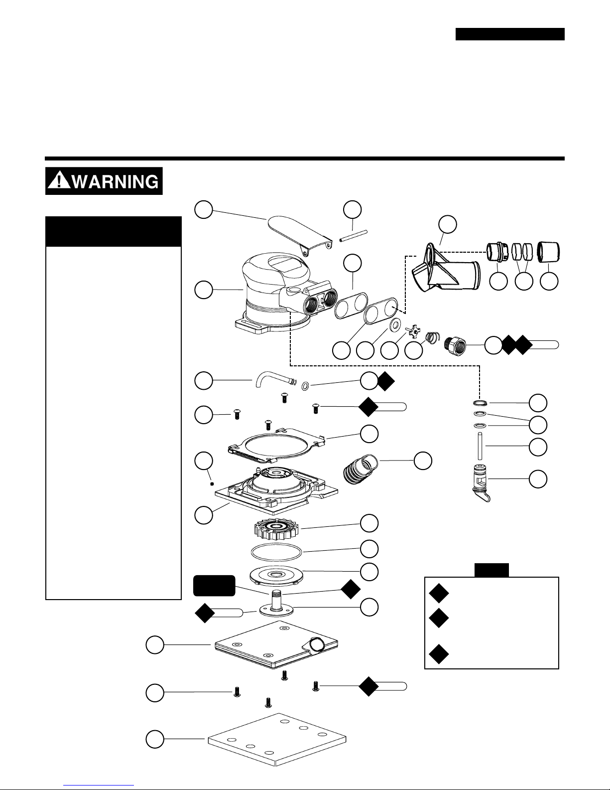
Index Key
No. Part # Description
1 53856 Throttle Lever
2 53861 Housing
3 57988 Inlet Hose Assembly
4 12156 O-Ring
5 96492 Button Head Screws (4)
6 57982 Clip Retainer
7 96493 Set Screw (3)
8 57971 Vac Base Plate
9 57942 Vacuum Tube
10 57981 Turbine Wheel Assembly
11 97121 O-Ring
12 57983 Base Plate Door
13 57979 Motor Shaft
14 53858 Vacuum Plate Assembly
15 95405 Button Head Screw (4)
16 56285 Hook Pad
56286 Vinly Pad
17 95979 Pin
18 53863 Gasket
19 53852 Plate Seal
20 01464 Seal
21 01472 Tip Valve
22 01468 Spring
23 01494 Inlet Bushing
24 57093 Vacuum Adapter
25 57066 Muffler Body
26 56027 Muffler Insert (2)
27 56028 Muffler Cap
28 95697 Snap Ring
29 01025 O-Ring
30 53857 Valve Stem
31 57064 Speed Regulator
A
T
Adhesive: A
2
= Loctite #271
A
6
= Loctite #380
A
8
= Loctite #567
Torque: N•m x 8.85 = In. - lbs.
G
A
2
G
1
A
8
Grease: G1= Lubriplate
630 AA
17
22
191820 21
29
30
31
28
1
2
3
6
9
10
11
12
13
14
15
16
5
7
Parts Page Reorder No. APD06•08
Effective June, 2006
Air Motor and Machine Parts
Models:
10485 — Vinyl-Face Pad
10487 — Hook-Face Pad
Dynabug “Model T”
Vacuum Sander
8
Always operate, inspect and maintain this tool in accordance with the Safety Code for portable air tools
(ANSI B186.1) and any other applicable safety codes and regulations. Please refer to Dynabrade
’
s
Warning/Safety Operating Instructions for more complete safety information.
3.4 N•m
T
KEY
4
23
T
AUTOMOTIVE
Left Hand
Threads
24
25 26 27
Page 2

2
One Year Warranty
Following the reasonable assumption that any inherent defect which might prevail in a product will become apparent to the user within one year from the
date of purchase, all equipment of our manufacture is warranted against defects in workmanship and materials under normal use and service. We shall
repair or replace at our factory, any equipment or part thereof which shall, within one year after delivery to the original purchaser, indicate upon our
examination to have been defective. Our obligation is contingent upon proper use of Dynabrade tools in accordance with factory recommendations,
instructions and safety practices. It shall not apply to equipment which has been subject to misuse, negligence, accident or tampering in any way so as to
affect its normal performance. Normally wearable parts such as bearings, contact wheels, rotor blades, etc., are not covered under this warranty.
Important Operating, Maintenance and Safety Instructions
Carefully read all instructions before operating or servicing any Dynabrade®Abrasive Power Tool.
Warning: Hand, wrist and arm injury may result from repetitive work motion and overexposure to vibration.
Operating Instructions:
Warning:Eye, face, sound, respiratory, and body protection must be worn while operating power tools. Failure to do so may result in serious
injury or death. Follow safety procedures posted in workplace.
1. With power source disconnected from tool, securely fasten abrasive/accessory on tool.
2. Install air fitting into inlet bushing of tool. Important: Secure inlet bushing of tool with a wrench before attempting to install the air fitting
to avoid damaging valve body housing.
3. Connect power source to tool. Be careful not to depress throttle lever in the process.
Maintenance Instructions:
1. Check tool speed regularly with a tachometer. If tool is operating at a higher speed than the RPM marked on the tool, the tool should be
serviced to correct the cause before use.
2. Some silencers on air tools may clog with use. Clean and replace as required.
3. Use only genuine Dynabrade replacement parts. To reorder replacement parts, specify the Model #, Serial #, and RPM of your machine.
4. A Motor Tune-Up Kit (P/N 96169) is available which includes assorted parts to help maintain motor in peek operating condition.
Please refer to Dynabrade’s Preventative Maintenance Schedule for a guide to expectant life of component parts.
5. Mineral spirits are recommended when cleaning the tool and parts. Do not clean tool or parts with any solvents or oils containing acids,
esters, keytones, chlorinated hydrocarbons or nitro carbons.
•
Important: User of tool is responsible for following accepted safety codes such as those published by the American National
Standards Institute (ANSI).
•
Always disconnect power supply before changing abrasive/accessory or making machine adjustments.
•
Inspect abrasives/accessories for damage or defects prior to installation on tools.
•
Please refer to Dynabrade’s Warning/Safety Operating Instructions Tag (Reorder No. 95903) for more complete safety information.
Notice
All Dynabrade motors use the highest quality parts and metals available and are machined to exacting tolerances. The failure of quality pneumatic
motors can most often be traced to an unclean air supply or the lack of lubrication. Air pressure easily forces dirt or water contained in the air supply
into motor bearings causing early failure. It often scores the cylinder walls and the rotor blades resulting in limited efficiency and power. Our
warranty obligation is contingent upon proper use of our tools and cannot apply to equipment which has been subjected to misuse such as unclean
air, wet air or a lack of lubrication during the use of this tool.
(APD01•12)
Safety Instructions:
Products offered by Dynabrade should not be converted or otherwise altered
from original design without expressed written consent from Dynabrade, Inc.
Model Pad Motor Sound Air Flow Rate Air Pressure Orbit Diameter Weight Length Height
Number Size RPM Level CFM/SCFM PSIG (Bars) Inch Pound Inch Inch
All Models Various 20,000 83 dB(A) 1/9 90 (6.2) 3/16 1 5 3
Additional Specifications: Air Inlet Thread 1/4" NPT
Page 3

Motor Assembly/Disassembly Instructions – Vacuum “Model T” Dynabug
Important: Manufacturers warranty is void if tool is disassembled before warranty expires.
A complete Repair Kit, part number 96169, is available which includes special tools for correct disassembly/assembly of tool.
To Disassemble
1. Disconnect tool from power source.
2. Remove sanding pad (if necessary).
3. Unscrew 96492 Button Head Screws (8).
4. Remove 57942 Vacuum Tube.
5. Separate and remove 53858 Vacuum Plate Assembly from 57971 Vacuum Base Plate.
6. Lift 57982 Clip Retainer up about 1/2", to expose 57971 Vacuum Base Plate.
7. Remove 57988 Hose from 57971 Vacuum Base Plate.
8. Disassemble housing assembly from base plate assembly, by pulling apart.
9. Invert assembly and insert spanner wrench to 57979 Motor Shaft, and remove (left-hand threads).
10. Remove 57981 Turbine Wheel Assembly. Note: Turbine orientation of wheel assembly on motor shaft.
To Assemble:
I
mportant: Be certain parts are clean and in good repair before assembling.
1. Replace 57981 Turbine Wheel Assembly on motor shaft using the same orientation as when it was disassembled.
2. Slide 57983 Base Plate Door onto 57979 Motor Shaft.
3. Apply a slight amount of #271 Loctite
®
(or equivalent) to 57979 Motor Shaft threads, torque 15 N•m/133 in. - lbs.
4. Install subassembly into base plate assembly.
5. Apply a slight amount of grease to the flared end of 57988 Inlet Hose and assemble onto housing. Install 12156 O-Ring.
Slide other end of tube over barb fitting in base plate (use adhesive if necessary).
6. Install housing assembly onto base plate assembly.
7. Slide 57982 Clip Retainer down onto 57971 Vacuum Base Plate and install (4) 96492 Button Head Screws, torque
3.4 N•m/30 in. - lbs.
8. Re-attach 53858 Vacuum Plate Assembly to 57971 Vacuum Base Plate. Secure with (4) 96492 Button Head Screws.
9. Re-attach 57942 Vacuum Tube to outlet hole of 53858 Vacuum Plate Assembly.
Tool Assembly Complete. Please allow 30 minutes for adhesives to cure before operating tool.
Valve and Speed Regulator Assemblies:
1. Secure housing in vice using 57092 Collar or padded jaws.
2. Remove 01494 Inlet Bushing, 01468 Spring, 01472 tip valve and 01464 Seal from housing.
3. Remove 95697 Snap Ring. Pull the speed regulator and valve stem out of the housing. Remove the 01025 O-Rings (2).
4. Place new 01025 O-Rings (2) on the speed regulator and place in housing with valve stem. Install new 95697 Snap Ring.
5. Place new 01464 Seal in housing. Using tweezers or needle nose pliers, place the tip valve into housing so that the pin
goes through the valve stem hole. Place new 01468 Spring into housing so small end is towards tip valve.
6. Place 1 drop of #567 Loctite
®
(or equivalent) on the threads of the inlet bushing and tighten into housing to
23 N•m/200 in. - lbs.
Note: This tool is an oil-free Dynabrade Tool. Therefore no air lube should be placed into the tool. Operate the machine for
approximately 30 seconds before application to workpiece to determine if machine is working properly and safely.
Loctite®is a registered trademark of the Loctite Corp.
3
Page 4

DYNABRADE, INC.,
8989 Sheridan Drive •Clarence, NY 14031-1490 •Phone: (716) 631-0100 •Fax: 716-631-2073 •International Fax: 716-631-2524
DYNABRADE EUROPE S.àr.l.,
Zone Artisanale •L-5485 Wormeldange—Haut, Luxembourg •Telephone: 352 76 84 94 1 •Fax: 352 76 84 95 1
© DYNABRADE, INC., 2006 PRINTED IN USA
Visit Our Web Site: www.dynabrade.com Email: Customer.Service@Dynabrade.com
Optional Accessories
96169 Motor Tune-Up Kit
•
Includes assorted parts to help
maintain and repair motor.
57092 Repair Collar
•
Specially designed collar for use in vise to
prevent damage to motor housing during
disassembly/assembly.
50971 Lock Ring Tool
•
Lock Ring Tool has a 3/8 in. square socket
for use with 3/8 in. drive; breaker bar,
ratchet head, or torque wrenches.
®
DYNABRADE
 Loading...