

Dynabrade Dynabug 57810, Dynabug 57812, Dynabug 57811, Dynabug 57813, Dynabug 57814 User Manual
Page 1

Junos®OS
Time Management Administration Guide for
Routing Devices
Release
13.3
Published: 2014-04-22
Copyright © 2014, Juniper Networks, Inc.
Page 2

Juniper Networks, Inc.
1194 North Mathilda Avenue
Sunnyvale, California 94089
USA
408-745-2000
www.juniper.net
Juniper Networks, Junos, Steel-Belted Radius, NetScreen, and ScreenOS are registered trademarks of Juniper Networks, Inc. in the United
States and other countries. The Juniper Networks Logo, the Junos logo, and JunosE are trademarks of Juniper Networks, Inc. All other
trademarks, service marks, registered trademarks, or registered service marks are the property of their respective owners.
Juniper Networks assumes no responsibility for any inaccuracies in this document. Juniper Networks reserves the right to change, modify,
transfer, or otherwise revise this publication without notice.
Junos®OS Time Management Administration Guide for Routing Devices
13.3
Copyright © 2014, Juniper Networks, Inc.
All rights reserved.
The information in this document is current as of the date on the title page.
YEAR 2000 NOTICE
Juniper Networks hardware and software products are Year 2000 compliant. Junos OS has no known time-related limitations through the
year 2038. However, the NTP application is known to have some difficulty in the year 2036.
END USER LICENSE AGREEMENT
The Juniper Networks product that is the subject of this technical documentation consists of (or is intended for use with) Juniper Networks
software. Use of such software is subject to the terms and conditions of the End User License Agreement (“EULA”) posted at
http://www.juniper.net/support/eula.html. By downloading, installing or using such software, you agree to the terms and conditions of
that EULA.
Copyright © 2014, Juniper Networks, Inc.ii
Page 3

Table of Contents
About the Documentation . . . . . . . . . . . . . . . . . . . . . . . . . . . . . . . . . . . . . . . . . . . . vii
Documentation and Release Notes . . . . . . . . . . . . . . . . . . . . . . . . . . . . . . . . . vii
Supported Platforms . . . . . . . . . . . . . . . . . . . . . . . . . . . . . . . . . . . . . . . . . . . . . vii
Using the Examples in This Manual . . . . . . . . . . . . . . . . . . . . . . . . . . . . . . . . . viii
Merging a Full Example . . . . . . . . . . . . . . . . . . . . . . . . . . . . . . . . . . . . . . . viii
Merging a Snippet . . . . . . . . . . . . . . . . . . . . . . . . . . . . . . . . . . . . . . . . . . . . ix
Documentation Conventions . . . . . . . . . . . . . . . . . . . . . . . . . . . . . . . . . . . . . . . ix
Documentation Feedback . . . . . . . . . . . . . . . . . . . . . . . . . . . . . . . . . . . . . . . . . xi
Requesting Technical Support . . . . . . . . . . . . . . . . . . . . . . . . . . . . . . . . . . . . . . xi
Self-Help Online Tools and Resources . . . . . . . . . . . . . . . . . . . . . . . . . . . . xi
Opening a Case with JTAC . . . . . . . . . . . . . . . . . . . . . . . . . . . . . . . . . . . . . xii
Part 1 Overview
Chapter 1 Time Management Overview . . . . . . . . . . . . . . . . . . . . . . . . . . . . . . . . . . . . . . . . 3
NTP Overview . . . . . . . . . . . . . . . . . . . . . . . . . . . . . . . . . . . . . . . . . . . . . . . . . . . . . . . 3
Understanding NTP Time Servers . . . . . . . . . . . . . . . . . . . . . . . . . . . . . . . . . . . . . . . 5
Part 2 Configuration
Chapter 2 Configuring Time . . . . . . . . . . . . . . . . . . . . . . . . . . . . . . . . . . . . . . . . . . . . . . . . . . . 9
Setting the Date and Time Locally . . . . . . . . . . . . . . . . . . . . . . . . . . . . . . . . . . . . . . 9
Configuring NTP . . . . . . . . . . . . . . . . . . . . . . . . . . . . . . . . . . . . . . . . . . . . . . . . . . . . 10
Modifying the Default Time Zone for a Router or Switch Running Junos OS . . . . . 12
Synchronizing and Coordinating Time Distribution Using NTP . . . . . . . . . . . . . . . . 13
Configuring NTP . . . . . . . . . . . . . . . . . . . . . . . . . . . . . . . . . . . . . . . . . . . . . . . . . 13
Configuring the NTP Boot Server . . . . . . . . . . . . . . . . . . . . . . . . . . . . . . . . . . . 13
Specifying a Source Address for an NTP Server . . . . . . . . . . . . . . . . . . . . . . . . 13
Configuring the NTP Time Server and Time Services . . . . . . . . . . . . . . . . . . . . . . . 14
Configuring the Router or Switch to Operate in Client Mode . . . . . . . . . . . . . . 15
Configuring the Router or Switch to Operate in Symmetric Active Mode . . . . 15
Configuring the Router or Switch to Operate in Broadcast Mode . . . . . . . . . . 16
Configuring the Router or Switch to Operate in Server Mode . . . . . . . . . . . . . 16
Example: Configuring NTP as a Single Time Source for Router and Switch Clock
Synchronization . . . . . . . . . . . . . . . . . . . . . . . . . . . . . . . . . . . . . . . . . . . . . . . . . 17
Configuring NTP Authentication Keys . . . . . . . . . . . . . . . . . . . . . . . . . . . . . . . . . . . 18
Configuring the Router or Switch to Listen for Broadcast Messages Using
NTP . . . . . . . . . . . . . . . . . . . . . . . . . . . . . . . . . . . . . . . . . . . . . . . . . . . . . . . . . . 19
Configuring the Router or Switch to Listen for Multicast Messages Using NTP . . . 19
iiiCopyright © 2014, Juniper Networks, Inc.
Page 4

Time Management Administration Guide for Routing Devices
Updating the IANA Time Zone Database on Junos Devices . . . . . . . . . . . . . . . . . . 20
Importing and Installing Time Zone Files . . . . . . . . . . . . . . . . . . . . . . . . . . . . . 20
Configuring a Custom Time Zone . . . . . . . . . . . . . . . . . . . . . . . . . . . . . . . . . . . 21
Chapter 3 Configuration Statements . . . . . . . . . . . . . . . . . . . . . . . . . . . . . . . . . . . . . . . . . . 23
System Management Configuration Statements . . . . . . . . . . . . . . . . . . . . . . . . . . 23
authentication-key . . . . . . . . . . . . . . . . . . . . . . . . . . . . . . . . . . . . . . . . . . . . . . . . . . 30
boot-server (NTP) . . . . . . . . . . . . . . . . . . . . . . . . . . . . . . . . . . . . . . . . . . . . . . . . . . 31
broadcast . . . . . . . . . . . . . . . . . . . . . . . . . . . . . . . . . . . . . . . . . . . . . . . . . . . . . . . . . 32
broadcast-client . . . . . . . . . . . . . . . . . . . . . . . . . . . . . . . . . . . . . . . . . . . . . . . . . . . . 33
multicast-client . . . . . . . . . . . . . . . . . . . . . . . . . . . . . . . . . . . . . . . . . . . . . . . . . . . . 33
ntp . . . . . . . . . . . . . . . . . . . . . . . . . . . . . . . . . . . . . . . . . . . . . . . . . . . . . . . . . . . . . . 34
peer (NTP) . . . . . . . . . . . . . . . . . . . . . . . . . . . . . . . . . . . . . . . . . . . . . . . . . . . . . . . . 35
server (NTP) . . . . . . . . . . . . . . . . . . . . . . . . . . . . . . . . . . . . . . . . . . . . . . . . . . . . . . . 36
source-address (NTP, RADIUS, System Logging, or TACACS+) . . . . . . . . . . . . . . . 37
system . . . . . . . . . . . . . . . . . . . . . . . . . . . . . . . . . . . . . . . . . . . . . . . . . . . . . . . . . . . 38
time-zone . . . . . . . . . . . . . . . . . . . . . . . . . . . . . . . . . . . . . . . . . . . . . . . . . . . . . . . . . 39
use-imported-time-zones . . . . . . . . . . . . . . . . . . . . . . . . . . . . . . . . . . . . . . . . . . . . 41
Part 3 Administration
Chapter 4 Operational Commands . . . . . . . . . . . . . . . . . . . . . . . . . . . . . . . . . . . . . . . . . . . 45
set date . . . . . . . . . . . . . . . . . . . . . . . . . . . . . . . . . . . . . . . . . . . . . . . . . . . . . . . . . . 46
Chapter 5 Monitoring Commands . . . . . . . . . . . . . . . . . . . . . . . . . . . . . . . . . . . . . . . . . . . . 47
show ntp associations . . . . . . . . . . . . . . . . . . . . . . . . . . . . . . . . . . . . . . . . . . . . . . . 48
show ntp status . . . . . . . . . . . . . . . . . . . . . . . . . . . . . . . . . . . . . . . . . . . . . . . . . . . . 50
Part 4 Index
Index . . . . . . . . . . . . . . . . . . . . . . . . . . . . . . . . . . . . . . . . . . . . . . . . . . . . . . . . . 55
Copyright © 2014, Juniper Networks, Inc.iv
Page 5

List of Tables
About the Documentation . . . . . . . . . . . . . . . . . . . . . . . . . . . . . . . . . . . . . . . . . . vii
Table 1: Notice Icons . . . . . . . . . . . . . . . . . . . . . . . . . . . . . . . . . . . . . . . . . . . . . . . . . . ix
Table 2: Text and Syntax Conventions . . . . . . . . . . . . . . . . . . . . . . . . . . . . . . . . . . . . x
Part 3 Administration
Chapter 5 Monitoring Commands . . . . . . . . . . . . . . . . . . . . . . . . . . . . . . . . . . . . . . . . . . . . 47
Table 3: show ntp associations Output Fields . . . . . . . . . . . . . . . . . . . . . . . . . . . . 48
Table 4: show ntp status Output Fields . . . . . . . . . . . . . . . . . . . . . . . . . . . . . . . . . 50
vCopyright © 2014, Juniper Networks, Inc.
Page 6

Time Management Administration Guide for Routing Devices
Copyright © 2014, Juniper Networks, Inc.vi
Page 7

About the Documentation
•
Documentation and Release Notes on page vii
•
Supported Platforms on page vii
•
Using the Examples in This Manual on page viii
•
Documentation Conventions on page ix
•
Documentation Feedback on page xi
•
Requesting Technical Support on page xi
Documentation and Release Notes
To obtain the most current version of all Juniper Networks®technical documentation,
see the product documentation page on the Juniper Networks website at
http://www.juniper.net/techpubs/.
If the information in the latest release notes differs from the information in the
documentation, follow the product Release Notes.
Juniper Networks Books publishes books by Juniper Networks engineers and subject
matter experts. These books go beyond the technical documentation to explore the
nuances of network architecture, deployment, and administration. The current list can
be viewed at http://www.juniper.net/books.
Supported Platforms
For the features described in this document, the following platforms are supported:
•
M Series
•
MX Series
•
T Series
•
J Series
•
EX Series
•
PTX Series
viiCopyright © 2014, Juniper Networks, Inc.
Page 8

Time Management Administration Guide for Routing Devices
Using the Examples in This Manual
If you want to use the examples in this manual, you can use the load merge or the load
merge relative command. These commands cause the software to merge the incoming
configuration into the current candidate configuration. The example does not become
active until you commit the candidate configuration.
If the example configuration contains the top level of the hierarchy (or multiple
hierarchies), the example is a full example. In this case, use the load merge command.
If the example configuration does not start at the top level of the hierarchy, the example
is a snippet. In this case, use the load merge relative command. These procedures are
described in the following sections.
Merging a Full Example
To merge a full example, follow these steps:
1. From the HTML or PDF version of the manual, copy a configuration example into a
text file, save the file with a name, and copy the file to a directory on your routing
platform.
For example, copy thefollowingconfigurationto a file and name the file ex-script.conf.
Copy the ex-script.conf file to the /var/tmp directory on your routing platform.
system {
scripts {
commit {
file ex-script.xsl;
}
}
}
interfaces {
fxp0 {
disable;
unit 0 {
family inet {
address 10.0.0.1/24;
}
}
}
}
2. Merge the contents of the file into your routing platform configuration by issuing the
load merge configuration mode command:
[edit]
user@host# load merge /var/tmp/ex-script.conf
load complete
Copyright © 2014, Juniper Networks, Inc.viii
Page 9
Merging a Snippet
About the Documentation
To merge a snippet, follow these steps:
1. From the HTML or PDF version of the manual, copy a configuration snippet into a text
file, save the file with a name, and copy the file to a directory on your routing platform.
For example, copy the following snippet to a file and name the file
ex-script-snippet.conf. Copy the ex-script-snippet.conf file to the /var/tmp directory
on your routing platform.
commit {
file ex-script-snippet.xsl; }
2. Move to the hierarchy level that is relevant for this snippet by issuing the following
configuration mode command:
[edit]
user@host# edit system scripts
[edit system scripts]
3. Merge the contents of the file into your routing platform configuration by issuing the
load merge relative configuration mode command:
[edit system scripts]
user@host# load merge relative /var/tmp/ex-script-snippet.conf
load complete
For more information about the load command, see the CLI User Guide.
Documentation Conventions
Table 1 on page ix defines notice icons used in this guide.
Table 1: Notice Icons
DescriptionMeaningIcon
Indicates important features or instructions.Informational note
Indicates a situation that might result in loss of data or hardware damage.Caution
Alerts you to the risk of personal injury or death.Warning
Alerts you to the risk of personal injury from a laser.Laser warning
Table 2 on page x defines the text and syntax conventions used in this guide.
ixCopyright © 2014, Juniper Networks, Inc.
Page 10

Time Management Administration Guide for Routing Devices
Table 2: Text and Syntax Conventions
ExamplesDescriptionConvention
Fixed-width text like this
Italic text like this
Italic text like this
Text like this
Represents text that you type.Bold text like this
Represents output that appears on the
terminal screen.
•
Introduces or emphasizes important
new terms.
•
Identifies guide names.
•
Identifies RFC and Internet draft titles.
Represents variables (options for which
you substitute a value) in commands or
configuration statements.
Represents names of configuration
statements, commands, files, and
directories;configurationhierarchylevels;
or labels on routing platform
components.
To enter configuration mode, type the
configure command:
user@host> configure
user@host> show chassis alarms
No alarms currently active
•
A policy term is a named structure
that defines match conditions and
actions.
•
Junos OS CLI User Guide
•
RFC 1997, BGP Communities Attribute
Configure the machine’s domain name:
[edit]
root@# set system domain-name
domain-name
•
To configure a stub area, include the
stub statement at the [edit protocols
ospf area area-id] hierarchy level.
•
The console port islabeledCONSOLE.
stub <default-metric metric>;Encloses optional keywords orvariables.< > (angle brackets)
| (pipe symbol)
# (pound sign)
[ ] (square brackets)
Indention and braces ( { } )
; (semicolon)
GUI Conventions
Indicates a choice between the mutually
exclusivekeywords or variables on either
side of the symbol. The set of choices is
often enclosed in parentheses for clarity.
same lineas the configuration statement
to which it applies.
Encloses a variable for which you can
substitute one or more values.
Identifies a level in the configuration
hierarchy.
Identifies a leaf statement at a
configuration hierarchy level.
broadcast | multicast
(string1 | string2 | string3)
rsvp { # Required for dynamic MPLS onlyIndicates a comment specified on the
community name members [
community-ids ]
[edit]
routing-options {
static {
route default {
nexthop address;
retain;
}
}
}
Copyright © 2014, Juniper Networks, Inc.x
Page 11

Table 2: Text and Syntax Conventions (continued)
Bold text like this
Representsgraphicaluser interface (GUI)
items you click or select.
About the Documentation
ExamplesDescriptionConvention
•
In the Logical Interfaces box, select
All Interfaces.
•
To cancel the configuration, click
Cancel.
> (bold right angle bracket)
Documentation Feedback
We encourage you to provide feedback, comments, and suggestions so that we can
improve the documentation. You can send your comments to
techpubs-comments@juniper.net, or fill out the documentation feedback form at
https://www.juniper.net/cgi-bin/docbugreport/. If you are using e-mail, be sure to include
the following information with your comments:
•
Document or topic name
•
URL or page number
•
Software release version (if applicable)
Requesting Technical Support
Technical productsupport is availablethrough theJuniper Networks Technical Assistance
Center (JTAC). If you are a customer with an active J-Care or JNASC support contract,
or are covered under warranty, and need post-sales technical support, you can access
our tools and resources online or open a case with JTAC.
Separates levels in a hierarchy of menu
selections.
In the configuration editor hierarchy,
select Protocols>Ospf.
•
JTAC policies—For a complete understanding of our JTAC procedures and policies,
review the JTAC User Guide located at
http://www.juniper.net/us/en/local/pdf/resource-guides/7100059-en.pdf.
•
Product warranties—For product warranty information, visit
http://www.juniper.net/support/warranty/.
•
JTAC hours of operation—The JTAC centers have resources available 24 hours a day,
7 days a week, 365 days a year.
Self-Help Online Tools and Resources
For quick and easy problem resolution, Juniper Networks has designed an online
self-service portal called the Customer Support Center (CSC) that provides you with the
following features:
•
Find CSC offerings: http://www.juniper.net/customers/support/
•
Search for known bugs: http://www2.juniper.net/kb/
xiCopyright © 2014, Juniper Networks, Inc.
Page 12

Time Management Administration Guide for Routing Devices
•
Find product documentation: http://www.juniper.net/techpubs/
•
Find solutions and answer questions using our Knowledge Base: http://kb.juniper.net/
•
Download the latest versions of software and review release notes:
http://www.juniper.net/customers/csc/software/
•
Search technical bulletins for relevant hardware and software notifications:
http://kb.juniper.net/InfoCenter/
•
Join and participate in the Juniper Networks Community Forum:
http://www.juniper.net/company/communities/
•
Open a case online in the CSC Case Management tool: http://www.juniper.net/cm/
To verifyservice entitlement by product serialnumber,use ourSerial Number Entitlement
(SNE) Tool: https://tools.juniper.net/SerialNumberEntitlementSearch/
Opening a Case with JTAC
You can open a case with JTAC on the Web or by telephone.
•
Use the Case Management tool in the CSC at http://www.juniper.net/cm/.
•
Call 1-888-314-JTAC (1-888-314-5822 toll-free in the USA, Canada, and Mexico).
For international or direct-dial options in countries without toll-free numbers, see
http://www.juniper.net/support/requesting-support.html.
Copyright © 2014, Juniper Networks, Inc.xii
Page 13

PART 1
Overview
•
Time Management Overview on page 3
1Copyright © 2014, Juniper Networks, Inc.
Page 14

Time Management Administration Guide for Routing Devices
Copyright © 2014, Juniper Networks, Inc.2
Page 15

CHAPTER 1
Time Management Overview
•
NTP Overview on page 3
•
Understanding NTP Time Servers on page 5
NTP Overview
Network Time Protocol (NTP) is a widely used protocol used to synchronize the clocks
of routers and other hardware devices on the Internet. Primary NTP servers are
synchronizedto areferenceclock directlytraceableto Coordinated Universal Time(UTC).
Reference clocks include GPS receivers and telephone modem services, NTP accuracy
expectations depend on the environment application requirements, however, NTP can
generally maintain time to within tens of milliseconds over the public internet.
NTP isdefined inthe RFC5905: Network Time Protocol Version4: Protocol and Algorithms
Specification
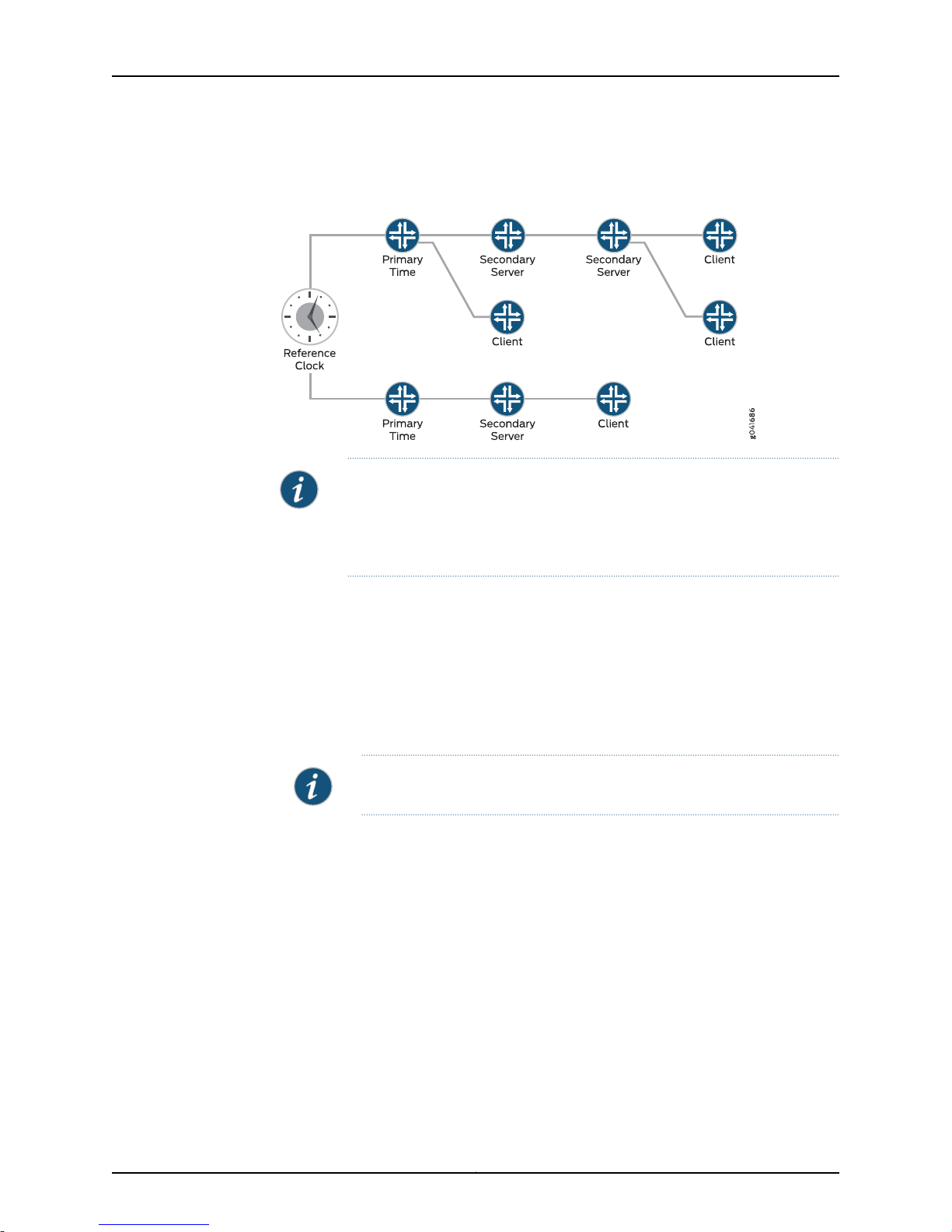
Junos devices can be configured to act as an NTP client, a secondary NTP server, or a
primary NTP server. These variations are as follows:
•
Primary NTP Server—Primary NTP servers are synchronized to a reference clock that
is directly traceableto UTC. These servers then re-distribute thistime data downstream
to other Secondary NTP servers or NTP clients.
•
Secondary NTP Server—Secondary NTP servers are synchronized to a primary or
secondary NTP server. These servers then re-distribute this data downstream to other
Secondary NTP servers or NTP clients.
3Copyright © 2014, Juniper Networks, Inc.
Page 16
Time Management Administration Guide for Routing Devices
•
NTP Client—NTP clients aresynchronizedto aprimary or secondaryNTP server.Clients
do not re-distribute this time data to other devices.
NOTE: The NTP subnet includes a number of widely accessible public primary
time servers that can be used as a network’s primary NTP server. Juniper
Networks strongly recommends that you authenticate any primary servers
you use.
Each device on your network can be configured to run in one or more of the following
NTP modes:
•
Broadcast Mode—One or more devices is set up to transmit time information to a
specified broadcast or multicast address. Other devices listen time sync packets on
these addresses. This mode is less accurate than the client/server mode.
•
Client/Server Mode—Devices are organized hierarchically across the network in
client/server relationships.
NOTE: QFX devices cannot be act as NTP servers, only clients.
•
Symmetric Active (peer) Mode—Two or more devices are configured as NTP server
peers to provide redundancy.
By default, if an NTP client time drifts so that the difference in time from the NTP server
exceeds 128 milliseconds, the NTP client is automatically stepped back into
synchronization. The NTP client will still synchronize with the server even if the offset
betweenthe NTP client and server exceeds the 1000-secondthreshold.You can manually
request that adevice synchronize with an NTP serverby using the set datentp operational
command on the router. On devices running Junos OS that have dual Routing Engines,
the backup Routing Engine synchronizes directly with the master Routing Engine.
For more details on the Network Time Protocol, go to the Network Time Foundation
website at http://www.ntp.org.
Copyright © 2014, Juniper Networks, Inc.4
Page 17

Chapter 1: Time Management Overview
NOTE: NTP is required for Common Criteria compliance. For more information
on the Common Criteria certification, see Public Sector Certifications.
In Junosoperating system (Junos OS) Release 11.2or later, NTPsupports IPv4VPN routing
and forwarding (VRF) requests. This enables an NTP server running on a provider edge
(PE) router to respond to NTP requests from a customer edge (CE) router. As a result,
a PE router can process anyNTP request packet coming fromdifferent routing instances.
In Junos OS Release 11.4 and later, NTP also supports IPv6 VRF requests.
Related
Documentation
Synchronizing and Coordinating Time Distribution Using NTP on page 13•
• Example: Configuring NTP as a Single Time Source for Router and Switch Clock
Synchronization on page 17
Understanding NTP Time Servers
The IETF defined the NetworkTime Protocol(NTP) tosynchronize the clocks ofcomputer
systems connected to each other over a network. Most large networks have an NTP
server that ensures that time on all devices is synchronized, regardless of the device
location. If you useone or more NTP servers on your network, ensure you include the NTS
server addresses in your Junos OS configuration.
When configuring the NTP, you can specify which system on the network is the
authoritative time source, or time server, and how time is synchronized between systems
on the network. To do this, you configure the router, switch, or security device to operate
in one of the following modes:
•
Client mode—In this mode, the local router or switch can be synchronized with the
remote system, but the remote system cannever be synchronized with thelocal router
or switch.
•
Symmetricactive mode—Inthis mode,the local router orswitch andthe remote system
can synchronize with each other. You use this mode in a network in which either the
local router or switch or the remote system might be a better source of time.
•
Broadcast mode—In this mode, the local router or switch sends periodic broadcast
messages to a client population at the specified broadcast or multicast address.
Normally, you include this statement only when the local router or switch is operating
as a transmitter.
•
Server mode—In this mode, the local router or switch operates as an NTP server.
NOTE: Symmetric active mode can be initiated by either the local or the
remote system. Only one system needs to be configured to do so. This
means that the local system can synchronize with any system that offers
symmetric active mode without any configuration whatsoever. However,
we strongly encourage you to configure authentication to ensure that the
local system synchronizes only with known time servers.
5Copyright © 2014, Juniper Networks, Inc.
Page 18

Time Management Administration Guide for Routing Devices
NOTE: In NTP server mode, the Junos OS supports authentication as
follows:
•
If the NTP request from the client comes with an authentication key
(such as a key ID and message digest sent with the packet), the request
is processed and answered based on the authentication key match.
•
If the NTP request from the client comes without any authentication key,
the request is processed and answered without authentication.
Related
Documentation
• Configuring the NTP Time Server and Time Services
• Example: Configuring NTP as a Single Time Source for Router and Switch Clock
Synchronization on page 17
Copyright © 2014, Juniper Networks, Inc.6
Page 19

PART 2
Configuration
•
Configuring Time on page 9
•
Configuration Statements on page 23
7Copyright © 2014, Juniper Networks, Inc.
Page 20

Time Management Administration Guide for Routing Devices
Copyright © 2014, Juniper Networks, Inc.8
Page 21

CHAPTER 2
Configuring Time
•
Setting the Date and Time Locally on page 9
•
Configuring NTP on page 10
•
Modifying the Default Time Zone for a Router or Switch Running Junos OS on page 12
•
Synchronizing and Coordinating Time Distribution Using NTP on page 13
•
Configuring the NTP Time Server and Time Services on page 14
•
Example: Configuring NTP as a Single Time Source for Router and Switch Clock
Synchronization on page 17
•
Configuring NTP Authentication Keys on page 18
•
Configuring the Router or Switch to Listen for Broadcast Messages Using
NTP on page 19
•
Configuring the Router or Switch to Listen for MulticastMessagesUsing NTP on page 19
•
Updating the IANA Time Zone Database on Junos Devices on page 20
Setting the Date and Time Locally
You can set the device time on the command-line using the set date operational
command:
To set the time in your Junos OS device, you can either configure it manually, or your
device can take a system time from an Network Time Protocol (NTP) server. If you do
not have access to an NTP server, you can configure Junos OS to keep its own local time
using an onboard clock.
To set time locally:
1. From operational mode, manually set the date and time.
Because this is an operational-mode command, there is noneed to perform a commit
operation.
user@host> set date YYYYMMDDhhmm.ss
For example:
user@host> set date 201307251632
Thu Jul 25 16:32:00 PDT 2013
2. Verify the time.
9Copyright © 2014, Juniper Networks, Inc.
Page 22

Time Management Administration Guide for Routing Devices
The show system uptime command provides the following information: current time,
last boot time, protocols start time, last configuration commit time.
user@host> show system uptime
Current time: 2013-07-25 16:33:38 PDT
System booted: 2013-07-11 17:14:25 PDT (1w6d 23:19 ago)
Protocols started: 2013-07-11 17:16:35 PDT (1w6d 23:17 ago)
Last configured: 2013-07-23 12:32:42 PDT (2d 04:00 ago) by user
4:33PM up 13 days, 23:19, 1 user, load averages: 0.00, 0.01, 0.00
Related
Documentation
Configuring NTP
Time Management Administration Guide for Routing Devices•
The Network Time Protocol (NTP) provides the mechanisms to synchronize time and
coordinate time distribution in a large, diverse network. Debugging and troubleshooting
are much easier when the timestamps in the log files of all the routers or switches are
synchronized,because events that spanthe networkcan be correlatedwith synchronous
entries in multiple logs. We recommend using the Network Time Protocol (NTP) to
synchronize the system clocks of routers, switches, and other network equipment.
To configure NTP:
1. Configure Junos OS to retrieve the time when it first boots up.
Use the boot-server statement with the IP address of your NTP server. If DNS is
configured, you can use a domain name instead of an IP address.
[edit system ntp]
user@host# set boot-server (name | ip-address)
For example, set an IP address of 172.16.1.1 for your NTP server.
[edit system ntp]
user@host# set boot-server 172.16.1.1
For example, set a domain name. In this example, the domain name is provided by
pool.ntp.org.
[edit system ntp]
user@host# set boot-server 0.north-america.pool.ntp.org
2. (Optional) Configure one or more reference NTP servers to keep the device
synchronized with periodic updates.
It is a good practice to do this, as the Junos OS device can remain up for a long time,
and therefore the clock can drift.
[edit system ntp]
user@host# set server (name | ip-address)
For example, set an IP address of 172.16.1.1 for your NTP server.
[edit system ntp]
user@host# set server 172.16.1.1
For example, set a domain name provided by pool.ntp.org.
Copyright © 2014, Juniper Networks, Inc.10
Page 23

Chapter 2: Configuring Time
[edit system ntp]
user@host# set server 0.north-america.pool.ntp.org
3. (Optional) Set the local time zone to match the device’s location.
Universal Coordinated Time (UTC) is the default. Many administrators prefer to keep
all their devices configured to use the UTC time zone. This approach has the benefit
of allowing you to easily compare the time stamps of logs and other events across a
network of devices in many different time zones.
On the other hand, setting the time zone allows Junos OS to present the time in the
correct local format.
[edit system ntp]
user@host# set time-zone time-zone
For example:
[edit system ntp]
user@host# set time-zone America/Los_Angeles
4. Verify the configuration.
Check the system uptime. This command provides the current time, when the device
was last booted, whenthe protocolsstarted,and when the devicewaslast configured.
user@host> show system uptime
Current time: 2013-07-25 16:33:38 PDT
System booted: 2013-07-11 17:14:25 PDT (1w6d 23:19 ago)
Protocols started: 2013-07-11 17:16:35 PDT (1w6d 23:17 ago)
Last configured: 2013-07-23 12:32:42 PDT (2d 04:00 ago) by user
4:33PM up 13 days, 23:19, 1 user, load averages: 0.00, 0.01, 0.00
Check the NTP server status and associations of the clocking sources used by your
device.
user@host> show ntp associations
remote refid st t when poll reach delay offset jitter
==============================================================================
tux.brhelwig.co .INIT. 16 - - 512 0 0.000 0.000 4000.00
user@host > show ntp status
status=c011 sync_alarm, sync_unspec, 1 event, event_restart,
version="ntpd 4.2.0-a Thu May 30 19:14:15 UTC 2013 (1)",
processor="i386", system="JUNOS13.2-20130530_ib_13_3_psd.1", leap=11,
stratum=16, precision=-18, rootdelay=0.000, rootdispersion=5.130,
peer=0, refid=INIT,
reftime=00000000.00000000 Wed, Feb 6 2036 22:28:16.000, poll=4,
clock=d59d4f2e.1793bce9 Fri, Jul 26 2013 12:40:30.092, state=1,
offset=0.000, frequency=62.303, jitter=0.004, stability=0.000
Related
Documentation
Understanding NTP Time Servers on page 5•
• Time Management Administration Guide for Routing Devices
11Copyright © 2014, Juniper Networks, Inc.
Page 24

Time Management Administration Guide for Routing Devices
Modifying the Default Time Zone for a Router or Switch Running Junos OS
The default local time zone on the router is UTC (Coordinated Universal Time, formerly
known as Greenwich Mean Time, or GMT). To modify the local time zone, include the
time-zone statement at the [edit system] hierarchy level:
[edit system]
time-zone (GMThour-offset | time-zone);
You can use the GMT hour-offset option to set the time zone relative to UTC (GMT) time.
By default, hour-offset is 0. You can configure this to be a value in the range from –14 to
+12.
You can also specify time-zone as a string such as PDT (Pacific Daylight Time) or WET
(Western European Time), or specify the continent and major city.
NOTE: Junos OS complies with the POSIX time-zone standard, which is
counter-intuitive to the way time zones are generally indicated relative to
UTC.A time zone ahead of UTC (east of the Greenwich meridian) is commonly
indicated as GMT +n; for example, the Central European Time (CET) zone is
indicated as GMT +1. However, this is not true for POSIX time zone
designations. POSIX indicates CET as GMT-1. If you include the set system
time-zone GMT+1 statement for a router in the CET zone, your router time will
be set to one hour behind GMT, or two hours behind the actual CET time. For
this reason, you might find it easier to use the POSIX time-zone strings, which
you can list by entering set system time-zone ?.
Related
Documentation
For the time zone change to take effect for all processes running on the router or switch,
you must reboot the router or switch.
The followingexampleshows how to change thecurrent time zoneto America/New_York:
[edit]
user@host# set system time-zone America/New_York
[edit]
user@host# show
system {
time-zone America/New_York;
}
NTP Overview on page 3•
• Updating the IANA Time Zone Database on Junos Devices on page 20
Copyright © 2014, Juniper Networks, Inc.12
Page 25

Synchronizing and Coordinating Time Distribution Using NTP
Using NTP to synchronize and coordinate time distribution in a large network involves
these tasks:
1.
Configuring NTP on page 13
2.
Configuring the NTP Boot Server on page 13
3.
Specifying a Source Address for an NTP Server on page 13
Configuring NTP
To configure NTP on the router or switch, include the ntp statement at the [edit system]
hierarchy level:
[edit system]
ntp {
authentication-key number type type value password;
boot-server (address | hostname);
broadcast <address> <key key-number> <version value> <ttl value>;
broadcast-client;
multicast-client <address>;
peer address <key key-number> <version value> <prefer>;
server address <key key-number> <version value> <prefer>;
source-address source-address;
trusted-key [ key-numbers ];
}
Chapter 2: Configuring Time
Configuring the NTP Boot Server
When you boot the router or switch, it issues an ntpdate request, which polls a network
server to determine the localdate and time. You needto configure aserver that therouter
or switch uses to determine the time when the router or switch boots. If you configure
an NTP boot server, then when the router or switch boots, it immediately synchronizes
with the boot server even if the NTP process is explicitly disabled or if the time difference
between the client and the boot server exceeds the threshold value of 1000 seconds.
To configure the NTP boot server, include the boot-server statement at the [edit system
ntp] hierarchy level:
[edit system ntp]
boot-server (address | hostname);
Specify theaddress ofthe network server. You must specify an IP address or a hostname.
Specifying a Source Address for an NTP Server
For IPversion 4(IPv4), youcan specifythat ifthe NTPserver configured at the [edit system
ntp] hierarchy level is contacted on one of the loopback interface addresses, the reply
always uses a specific source address. This is useful for controlling which source address
NTP will use to access your network when it is either responding to an NTP client request
from your network or when it itself is sending NTP requests to your network.
13Copyright © 2014, Juniper Networks, Inc.
Page 26

Time Management Administration Guide for Routing Devices
To configure the specific source address that the reply will always use, and the source
address that requests initiated by NTP server will use, include the source-address
statement at the [edit system ntp] hierarchy level:
[edit system ntp]
source-address source-address;
source-address is a valid IP address configured on one of the router or switch interfaces.
NOTE: If a firewall filter is applied on the loopback interface, ensure that the
source-address specified for the NTP server at the [edit system ntp] hierarchy
level is explicitly included as one of the match criteria in the firewall filter.
This enables the Junos OS to accept traffic on the loopback interface from
the specified source address.
The following example shows a firewall filter with the source address
10.0.10.100 specified in the from statement included at the [edit firewall filter
firewall-filter-name] hierarchy:
[edit firewall filter Loopback-Interface-Firewall-Filter]
term Allow-NTP {
from {
source-address {
172.17.27.46/32; // IP address of the NTP server
10.0.10.100/32; // Source address specified for the NTP server
}
then accept;
}
}
If no source-address is configured for the NTP server, include the primary
address of the loopback interface in the firewall filter.
Related
Documentation
NTP Overview on page 3•
• Understanding NTP Time Servers on page 5
• Example: Configuring NTP as a Single Time Source for Router and Switch Clock
Synchronization on page 17
Configuring the NTP Time Server and Time Services
When you use NTP, configure the router or switch to operate in one of the following
modes:
•
Client mode
•
Symmetric active mode
•
Broadcast mode
•
Server mode
Copyright © 2014, Juniper Networks, Inc.14
Page 27

The following topics describe how to configure these modes of operation:
1.
Configuring the Router or Switch to Operate in Client Mode on page 15
2.
Configuring the Router or Switch to Operate in Symmetric Active Mode on page 15
3.
Configuring the Router or Switch to Operate in Broadcast Mode on page 16
4.
Configuring the Router or Switch to Operate in Server Mode on page 16
Configuring the Router or Switch to Operate in Client Mode
To configure the local router or switch to operate in client mode, include the server
statement and other optional statements at the [edit system ntp] hierarchy level:
[edit system ntp]
server address <key key-number> <version value> <prefer>;
authentication-key key-number type type value password;
boot-server address;
trusted-key [ key-numbers ];
Specify theaddress ofthe system actingas the time server. You must specify an address,
not a hostname.
Chapter 2: Configuring Time
To include an authentication key in all messages sent to the time server, include the key
option. The key corresponds to the key number you specify in the authentication-key
statement, as described in “Configuring NTP Authentication Keys” on page 18.
By default, the router or switch sends NTP version 4 packets to the time server. To set
the NTP version level to 1, 2, or 3, include the version option.
If you configure more thanone timeserver,you can markone server preferred by including
the prefer option.
For information about how to configure trusted keys, see “ConfiguringNTP Authentication
Keys” on page 18. For information about how to configure an NTP boot server, see
“Configuring the NTP Boot Server” on page 13. For information about how to configure
the router or switch to operate in server mode, see “Configuring the Router or Switch to
Operate in Server Mode” on page 16.
The following example shows how to configure the router or switch to operate in client
mode:
[edit system ntp]
authentication-key 1 type md5 value "$9$EgfcrvX7VY4ZEcwgoHjkP5Q3CuREyv87";
boot-server 10.1.1.1;
server 10.1.1.1 key 1 prefer;
trusted-key 1;
Configuring the Router or Switch to Operate in Symmetric Active Mode
To configure the local router or switch to operate in symmetric active mode, include the
peer statement at the [edit system ntp] hierarchy level:
[edit system ntp]
peer address <key key-number> <version value> <prefer>;
15Copyright © 2014, Juniper Networks, Inc.
Page 28

Time Management Administration Guide for Routing Devices
Specify theaddress of the remote system. You must specify an address, nota hostname.
To include an authentication key in all messages sent to the remote system, include the
key option. The key corresponds to the key number you specify in the authentication-key
statement, as described in “Configuring NTP Authentication Keys” on page 18.
By default, the router or switch sends NTP version 4 packets to the remote system. To
set the NTP version level to 1, 2 or 3, include the version option.
If you configure more than one remote system, you can mark one system preferred by
including the prefer option:
peer address <key key-number> <version value> prefer;
Configuring the Router or Switch to Operate in Broadcast Mode
To configurethe local router orswitch to operate in broadcastmode, include thebroadcast
statement at the [edit system ntp] hierarchy level:
[edit system ntp]
broadcast address <key key-number> <version value> <ttl value>;
Specify the broadcast address on one of the local networks or a multicast address
assigned to NTP. You must specify an address, not a hostname. If the multicast address
is used, it must be 224.0.1.1.
To include an authentication key in all messages sent to the remote system, include the
key option. The key corresponds to the key number you specify in the authentication-key
statement, as described in “Configuring NTP Authentication Keys” on page 18.
By default, the router or switch sends NTP version 4 packets to the remote system. To
set the NTP version level to 1, 2, or 3, include the version option.
Configuring the Router or Switch to Operate in Server Mode
In server mode, the router or switch acts as an NTP server for clients when the clients are
configured appropriately. The only prerequisite for “ server mode” is that the router or
switch must be receiving time from another NTP peer or server. No other configuration
is necessary on the router or switch.
To configure the local router or switch to operate as an NTP server, include the following
statements at the [edit system ntp] hierarchy level:
[edit system ntp]
authentication-key key-number type type value password;
server address <key key-number> <version value> <prefer>;
trusted-key [ key-numbers ];
Specify theaddress ofthe system actingas the time server. You must specify an address,
not a hostname.
To include an authentication key in all messages sent to the time server, include the key
option. The key corresponds to the key number you specify in the authentication-key
statement, as described in “Configuring NTP Authentication Keys” on page 18.
Copyright © 2014, Juniper Networks, Inc.16
Page 29

Chapter 2: Configuring Time
By default, the router or switch sends NTP version 4 packets to the time server. To set
the NTP version level to 1,or 2, or 3, include the version option.
If you configure more thanone timeserver,you can markone server preferred by including
the prefer option.
For information about how to configure trusted keys, see “ConfiguringNTP Authentication
Keys” on page 18. For information about how to configure the router or switch to operate
in client mode, see “Configuring the Router or Switch to Operate in Client Mode” on
page 15.
The following example shows how to configure the router or switch to operate in server
mode:
[edit system ntp]
authentication-key 1 type md5 value "$9$txERuBEreWx-wtuLNdboaUjH.T3AtOESe";
server 172.17.27.46 prefer;
trusted-key 1;
NOTE: When a host is added as an NTP server, it resolves to an IP address
prior to being adding to the configuration. When using a public NTP server,
the host might resolve to different IP addresses.
If the resolved IP address becomes unreachable for any reason, the switch
cannot access the NTP server. In order to leverage public NTP pool entities,
this functionality has been modified so that a host is accepted as a string
without DNS resolution.
Related
Documentation
Understanding NTP Time Servers on page 5•
• Example: Configuring NTP as a Single Time Source for Router and Switch Clock
Synchronization on page 17
Example: Configuring NTP as a Single Time Source for Router and Switch Clock
Synchronization
Debugging and troubleshooting are much easier when the timestamps in the log files of
all the routers or switches are synchronized, because events that span the network can
be correlated with synchronous entries in multiple logs. We strongly recommend using
the Network Time Protocol (NTP) to synchronize the system clocks of routers, switches,
and other network equipment.
By default, NTP operates in an entirely unauthenticated manner. If a malicious attempt
to influence the accuracy of a router or switch’s clock succeeds, it could have negative
effects on system logging, make troubleshooting and intrusion detection more difficult,
and impede other management functions.
The following sample configuration synchronizes allthe routers or switches in the network
to a single time source. We recommend using authentication to make sure that the NTP
peer istrusted. The boot-server statement identifies the server fromwhich the initial time
17Copyright © 2014, Juniper Networks, Inc.
Page 30

Time Management Administration Guide for Routing Devices
of day and date is obtained when the router boots. The server statement identifies the
NTP server used for periodic time synchronization. The authentication-key statement
specifies that an HMAC-Message Digest 5 (MD5) scheme should be used to hash the
key value for authentication, which prevents the router or switch from synchronizing with
an attacker’s host posing as the time server.
[edit]
system {
ntp {
authentication-key 2 type md5 value "$9$aH1j8gqQ1gjyjgjhgjgiiiii"; # SECRET-DATA
boot-server 10.1.4.1;
server 10.1.4.2;
}
}
Related
NTP Overview on page 3•
Documentation
• Understanding NTP Time Servers on page 5
• authentication-key
• boot-server
• server
• show ntp associations on page 48
• show ntp status on page 50
Configuring NTP Authentication Keys
Time synchronization can be authenticated to ensure that the local router or switch
obtains its time services only from known sources. By default, network time
synchronization is unauthenticated. The system will synchronize to whatever system
appears to have the most accurate time. We strongly encourage you to configure
authentication of network time services.
To authenticate other time servers, include the trusted-key statement at the [edit system
ntp] hierarchy level. Only time servers transmitting network time packets that contain
one of the specified key numbers and whose key matches the value configured for that
key number are eligible tobe synchronizedto. Othersystems can synchronize to the local
router without being authenticated.
[edit system ntp]
trusted-key [ key-numbers ];
Each key can be any 32-bit unsigned integer except 0. Include the key option in the peer,
server, or broadcast statements to transmit the specified authentication key when
transmitting packets. The key is necessary if the remote system has authentication
enabled so that it can synchronize to the local system.
To define the authentication keys, include the authentication-key statement at the [edit
system ntp] hierarchy level:
Copyright © 2014, Juniper Networks, Inc.18
Page 31

Chapter 2: Configuring Time
[edit system ntp]
authentication-key key-number type type value password;
number is the key number, type is the authentication type (only Message Digest 5 [MD5]
is supported), and password is the password for this key. The key number, type, and
password must match on all systems using that particular key for authentication.
Related
Documentation
Understanding NTP Time Servers on page 5•
• Example: Configuring NTP as a Single Time Source for Router and Switch Clock
Synchronization on page 17
Configuring the Router or Switch to Listen for Broadcast Messages Using NTP
When you are using NTP, you can configure the local router or switch to listen for
broadcast messages on the local network to discover other servers on the same subnet
by including the broadcast-client statement at the [edit system ntp] hierarchy level:
[edit system ntp]
broadcast-client;
When the router or switch detects a broadcast message for the first time, it measures
the nominal network delay using a brief client-server exchange with the remote server.
It thenenters broadcastclient mode, inwhich it listens for, and synchronizes to, succeeding
broadcast messages.
To avoid accidental or malicious disruption in this mode, both the local and remote
systems must use authentication and the same trusted key and key identifier.
Related
Documentation
Configuring the Router or Switch to Listen for MulticastMessagesUsing NTP on page 19•
• Configuring the NTP Time Server and Time Services on page 14
• Example: Configuring NTP as a Single Time Source for Router and Switch Clock
Synchronization on page 17
Configuring the Router or Switch to Listen for Multicast Messages Using NTP
When you are usingNTP,you can configure thelocal router orswitch to listen for multicast
messages on the local network to discover otherservers onthe same subnet by including
the multicast-client statement at the [edit system ntp] hierarchy level:
[edit system ntp]
multicast-client <address>;
When the router or switch receives a multicast message for the first time, it measures
the nominal network delay using a brief client-server exchange with the remote server.
It thenenters multicastclient mode, in which it listens for, and synchronizes to, succeeding
multicast messages.
You can specifyone ormore IPaddresses. (Youmust specifyan address, nota hostname.)
If you do, the router or switch joins those multicast groups. If you do not specify any
addresses, the software uses 224.0.1.1.
19Copyright © 2014, Juniper Networks, Inc.
Page 32

Time Management Administration Guide for Routing Devices
To avoid accidental or malicious disruption in this mode, both the local and remote
systems must use authentication and the same trusted key and key identifier.
Related
Documentation
Configuring the Router or Switch to Listen for Broadcast Messages Using NTP on
•
page 19
• Configuring the NTP Time Server and Time Services on page 14
• Example: Configuring NTP as a Single Time Source for Router and Switch Clock
Synchronization on page 17
Updating the IANA Time Zone Database on Junos Devices
Junos devices use the tz database, also known as the IANA Time Zone Database to
manage time zones. This database is periodically updated by IANA to reflect political
and time changes. As such, you may need from time to time to update this file to ensure
the Junos devices continue to accurately reflect worldwide time zones and daylight
savings time intervals.
To update the IANA Time Zone Database, perform the following steps:
1.
Importing and Installing Time Zone Files on page 20
2.
Configuring a Custom Time Zone on page 21
Importing and Installing Time Zone Files
The IANA TimeZone Database is maintainedby the InternetAssigned Numbers Authority
(IANA), which is a department of the Internet Corporation for Assigned Names and
Numbers (ICANN). You can download the latest IANA Time Zone Database file from the
following URL: http://www.iana.org/time-zones.
The following steps will guide you through one method ofinstalling thefile to your device.
However, depending on your network access and other preferences, you may need to
modify these steps.
1. Log into the Junos device.
2. If you are in the CLI interface, open the shell interface.
device@user# start shell
3. Create a tz directory in the /var/tmp and navigate to that directory.
# mkdir /var/tmp/tz
# cd /var/tmp/tz
4. Using FTP, download the time zone files archive.
NOTE: FTP must be enabled on your device before you can use FTP. FTP
is enabled by adding the ftp statement into the [edit system services]
hierarchy.
# ftp ftp.iana.org/tz
Copyright © 2014, Juniper Networks, Inc.20
Page 33

Chapter 2: Configuring Time
# bin
# get tzdata-latest.tar.gz
NOTE: If needed, you can edit the above untarred files to createor modify
the time zones.
5. Select the names of time zone files to compile and feed them to the following script.
For example, to generate northamerica and asia tz files:
# /usr/libexec/ui/compile-tz northamerica asia
6. Enable the use of the generated tz files using the CLI:
[edit]
# set system use-imported-time-zones
[edit]
# set system time-zone ?
This should show the newly generated tz files in /var/db/zoneinfo/.
7. Set the time zone and commit the configuration:
[edit]
# set system time-zone <your-time-zone>
# commit
8. Verify that the time zone change has taken effect:
[edit]
# run show system uptime
Configuring a Custom Time Zone
To use a custom time zone, follow these steps:
1. Download a time zones archive (from a known or designated source) to the router or
switch. Compile thetime zonearchive using the zic time zone compiler, whichgenerates
tz files.
2. Using the CLI, configure the router or switch to enable the use of the generated tz files
as follows:
[edit]
user@host# set system use-imported-time-zones
3. Display the imported time zones (saved in the directory /var/db/zoneinfo/):
[edit]
user@host# set system time-zone ?
If you do not configure the router to use imported time zones, the Junos OS default
time zones are shown (saved in the directory /usr/share/zoneinfo/).
Related
Documentation
• Modifying the Default Time Zone for a Router or Switch Running Junos OS on page 12
• NTP Overview on page 3
• Understanding NTP Time Servers on page 5
21Copyright © 2014, Juniper Networks, Inc.
Page 34

Time Management Administration Guide for Routing Devices
• Example: Configuring NTP as a Single Time Source for Router and Switch Clock
Synchronization on page 17
• use-imported-time-zones on page 41
Copyright © 2014, Juniper Networks, Inc.22
Page 35

CHAPTER 3
Configuration Statements
•
System Management Configuration Statements on page 23
•
authentication-key on page 30
•
boot-server (NTP) on page 31
•
broadcast on page 32
•
broadcast-client on page 33
•
multicast-client on page 33
•
ntp on page 34
•
peer (NTP) on page 35
•
server (NTP) on page 36
•
source-address (NTP, RADIUS, System Logging, or TACACS+) on page 37
•
system on page 38
•
time-zone on page 39
•
use-imported-time-zones on page 41
System Management Configuration Statements
This topic lists all the configuration statements that you can include at the [edit system]
hierarchy level to configure system management features:
system {
accounting {
events [ login change-log interactive-commands ];
destination {
radius {
server {
server-address {
accounting-port port-number;
retry number;
secret password;
source-address address;
timeout seconds;
}
}
}
tacplus {
23Copyright © 2014, Juniper Networks, Inc.
Page 36

Time Management Administration Guide for Routing Devices
server {
server-address {
port port-number;
secret password;
single-connection;
timeout seconds;
}
}
}
}
}
archival {
configuration {
archive-sites {
ftp://<username>:<password>@<host>:<port>/<url-path>;
ftp://<username>:<password>@<host>:<port>/<url-path>;
}
transfer-interval interval;
transfer-on-commit;
}
}
allow-v4mapped-packets;
arp {
aging-timer minutes;
gratuitous-arp-delay;
gratuitous-arp-on-ifup;
interfaces;
passive-learning;
purging;
}
authentication-order [ authentication-methods ];
backup-router address <destination destination-address>;
commit {
fast-synchronize;
persist-groups-inheritance ;
server;
synchronize
}
synchronize;
(compress-configuration-files | no-compress-configuration-files);
default-address-selection;
dump-device (compact-flash | remove-compact | usb);
diag-port-authentication (encrypted-password “password” | plain-text-password);
dynamic-profile-options {
versioning;
}
domain-name domain-name;
domain-search [ domain-list ];
host-name hostname;
inet6-backup-router address <destination destination-address>;
internet-options {
tcp-mss mss-value;
(gre-path-mtu-discovery | no-gre-path-mtu-discovery);
icmpv4-rate-limit bucket-size bucket-size packet-rate packet-rate;
icmpv6-rate-limit bucket-size bucket-size packet-rate packet-rate;
(ipip-path-mtu-discovery | no-ipip-path-mtu-discovery);
Copyright © 2014, Juniper Networks, Inc.24
Page 37

Chapter 3: Configuration Statements
(ipv6-path-mtu-discovery | no-ipv6-path-mtu-discovery);
ipv6-path-mtu-discovery-timeout;
no-tcp-rfc1323-paws;
no-tcp-rfc1323;
(path-mtu-discovery | no-path-mtu-discovery);
source-port upper-limit <upper-limit>;
(source-quench | no-source-quench);
tcp-drop-synfin-set;
}
location {
altitude feet;
building name;
country-code code;
floor number;
hcoord horizontal-coordinate;
lata service-area;
latitude degrees;
longitude degrees;
npa-nxx number;
postal-code postal-code;
rack number;
vcoord vertical-coordinate;
}
login {
announcement text;
class class-name {
access-end;
access-start;
allow-commands “regular-expression”;
( allow-configuration | allow-configuration-regexps) “regular expression 1” “regular
expression 2”;
allowed-days;
deny-commands “regular-expression”;
( deny-configuration | deny-configuration-regexps ) “regular expression 1” “regular
expression 2 ”;
idle-timeout minutes;
login-script
login-tip;
permissions [ permissions ];
}
message text;
password {
change-type (set-transitions | character-set);
format (md5 | sha1 | des);
maximum-length length;
minimum-changes number;
minimum-length length;
}
retry-options {
backoff-threshold number;
backoff-factor seconds;
minimum-time seconds;
tries-before-disconnect number;
}
user username {
full-name complete-name;
25Copyright © 2014, Juniper Networks, Inc.
Page 38

Time Management Administration Guide for Routing Devices
uid uid-value;
class class-name;
authentication {
(encrypted-password “password” | plain-text-password);
ssh-rsa “public-key”;
ssh-dsa “public-key”;
}
}
}
login-tip number;
mirror-flash-on-disk;
name-server {
address;
}
no-multicast-echo;
no-redirects;
no-ping-record-route;
no-ping-time-stamp;
ntp {
authentication-key key-number type type value password;
boot-server address;
broadcast <address> <key key-number> <version value> <ttl value>;
broadcast-client;
multicast-client <address>;
peer address <key key-number> <version value> <prefer>;
source-address source-address;
server address <key key-number> <version value> <prefer>;
trusted-key [ key-numbers ];
}
ports {
auxiliary {
type terminal-type;
}
pic-console-authentication {
encrypted-password encrypted-password;
plain-text-password;
console {
insecure;
log-out-on-disconnect;
type terminal-type;
disable;
}
}
processes {
process--name (enable | disable) failover (alternate-media | other-routing-engine);
timeout seconds;
}
}
radius-server server-address {
accounting-port port-number;
port port-number;
retry number;
secret password;
source-address source-address;
timeout seconds;
}
Copyright © 2014, Juniper Networks, Inc.26
Page 39

Chapter 3: Configuration Statements
radius-options {
password-protocol mschap-v2;
}
attributes {
nas-ip-address ip-address;
root-authentication {
(encrypted-password “password” | plain-text-password);
ssh-rsa “public-key”;
ssh-dsa “public-key”;
}
(saved-core-context | no-saved-core-context);
saved-core-files saved-core-files;
scripts {
commit {
allow-transients;
file filename {
optional;
refresh;
refresh-from url;
source url;
}
traceoptions {
file <filename> <files number> <size size> <world-readable | no-world-readable>;
flag flag;
no-remote-trace;
}
op {
file filename {
arguments {
argument-name {
description descriptive-text;
}
}
command filename-alias;
description descriptive-text;
refresh;
refresh-from url;
source url;
}
refresh;
refresh-from url;
traceoptions {
file <filename> <files number> <size size> <world-readable | no-world-readable>;
flag flag;
no-remote-trace;
}
}
}
services {
finger {
connection-limit limit;
rate-limit limit;
}
flow-tap-dtcp {
ssh {
connection-limit limit;
27Copyright © 2014, Juniper Networks, Inc.
Page 40

Time Management Administration Guide for Routing Devices
rate-limit limit;
}
}
ftp {
connection-limit limit;
rate-limit limit;
}
service-deployment {
servers server-address {
port port-number;
}
source-address source-address;
}
ssh {
root-login (allow | deny | deny-password);
protocol-version [v1 v2];
connection-limit limit;
rate-limit limit;
}
telnet {
connection-limit limit;
rate-limit limit;
}
web-management {
http {
interfaces [ interface-names ];
port port;
}
https {
interfaces [ interface-names ];
local-certificate name;
port port;
}
session {
idle-timeout [ minutes ];
session-limit [ session-limit ];
}
}
xnm-clear-text {
connection-limit limit;
rate-limit limit;
}
xnm-ssl {
connection-limit limit;
local-certificate name;
rate-limit limit;
}
}
static-host-mapping {
hostname {
alias [ alias ];
inet [ address ];
sysid system-identifier;
}
}
syslog {
Copyright © 2014, Juniper Networks, Inc.28
Page 41

Chapter 3: Configuration Statements
archive <files number> <size size> <world-readable | no-world-readable>;
console {
facility severity;
}
file filename {
facility severity;
archive <archive-sites {ftp-url <password password>}> <files number> <size size>
<start-time "YYYY-MM-DD.hh:mm"> <transfer-interval minutes> <world-readable|
no-world-readable>;
explicit-priority;
match "regular-expression";
structured-data {
brief;
}
}
host (hostname | other-routing-engine | scc-master) {
facility severity;
explicit-priority;
facility-override facility;
log-prefix string;
match "regular-expression";
source-address source-address;
structured-data {
brief;
}
}
source-address source-address;
time-format (year | millisecond | year millisecond);
user (username | *) {
facility severity;
match "regular-expression";
}
}
tacplus-options {
service-name service-name;
(no-cmd-attribute-value | exclude-cmd-attribute);
}
tacplus-server server-address {
secret password;
single-connection;
source-address source-address;
timeout seconds;
}
time-zone (GMThour-offset | time-zone);
}
tracing {
destination-override {
syslog host;
}
}
use-imported-time-zones;
}
29Copyright © 2014, Juniper Networks, Inc.
Page 42

Time Management Administration Guide for Routing Devices
authentication-key
Syntax authentication-key key-number type type value password;
Hierarchy Level [edit system ntp]
Release Information Statement introduced before Junos OS Release 7.4.
Statement introduced in Junos OS Release 9.0 for EX Series switches.
Description Configure Network Time Protocol (NTP) authentication keys so that the router or switch
can send authenticated packets. If you configure the router or switch to operate in
authenticated mode, you must configure a key.
Both the keys and the authentication scheme (MD5) must be identical between a set of
peers sharing the same key number.
Options key-number—Positive integer that identifies the key.
type type—Authentication type. It can only be md5.
Required Privilege
Level
Related
Documentation
value password—The key itself, which can be from 1 through 8 ASCII characters. If the key
contains spaces, enclose it in quotation marks.
system—To view this statement in the configuration.
system-control—To add this statement to the configuration.
• Configuring NTP Authentication Keys on page 18
• broadcast on page 32
• peer on page 35
• server on page 36
• trusted-key
Copyright © 2014, Juniper Networks, Inc.30
Page 43

boot-server (NTP)
Syntax boot-server (address | hostname);
Hierarchy Level [edit system ntp]
Release Information Statement introduced before Junos OS Release 7.4.
Statement introduced in Junos OS Release 9.0 for EX Series switches.
Description Configure the server that NTP queries when the router or switch boots to determine the
local date and time.
When you boot the router or switch, it issues an ntpdate request, which polls a network
server to determine the localdate and time. You needto configure aserver that therouter
or switch uses to determine the time when the router or switch boots. You can either
configure an IP address or a hostname for the boot server. If you configure a hostname
instead of an IP address, the ntpdate request resolves the hostname to an IP address
when the router or switch boots up.
Chapter 3: Configuration Statements
Options • address—The IP address of an NTP boot server.
Required Privilege
Level
Related
Documentation
If you configure an NTP boot server, then when the router or switch boots, it immediately
synchronizes with the boot server even if the NTP process is explicitly disabled or if the
time difference between the client and the boot server exceeds the threshold value of
1000 seconds.
• hostname—The hostname of an NTP boot server.
system—To view this statement in the configuration.
system-control—To add this statement to the configuration.
• Configuring the NTP Boot Server on page 13
31Copyright © 2014, Juniper Networks, Inc.
Page 44

Time Management Administration Guide for Routing Devices
broadcast
Syntax broadcast address <key key-number> <version value> <ttl value>;
Hierarchy Level [edit system ntp]
Release Information Statement introduced before Junos OS Release 7.4.
Statement introduced in Junos OS Release 9.0 for EX Series switches.
Description Configure thelocalrouter or switchto operatein broadcastmode withthe remote system
at the specified address. In this mode, the local router or switch sends periodic broadcast
messagesto aclient population at thespecified broadcastor multicast address. Normally,
you include this statement only when the local router or switch is operating as a
transmitter.
Options address—The broadcast address on one of the local networks or a multicast address
assigned to NTP. You must specify an address, not a hostname. If the multicast
address is used, it must be 224.0.1.1.
Required Privilege
Level
Related
Documentation
key key-number—(Optional) All packets sent to the address include authentication fields
that are encrypted using the specified key number.
Range: Any unsigned 32-bit integer
ttl value—(Optional) Time-to-live (TTL) value to use.
Range: 1 through 255
Default: 1
version value—(Optional) Specify the version numberto beused inoutgoing NTP packets.
Range: 1 through 4
Default: 4
system—To view this statement in the configuration.
system-control—To add this statement to the configuration.
• Configuring the NTP Time Server and Time Services on page 14
Copyright © 2014, Juniper Networks, Inc.32
Page 45

broadcast-client
Syntax broadcast-client;
Hierarchy Level [edit system ntp]
Release Information Statement introduced before Junos OS Release 7.4.
Statement introduced in Junos OS Release 9.0 for EX Series switches.
Description Configure thelocal router or switch to listenfor broadcast messages onthe local network
to discover other servers on the same subnet.
Chapter 3: Configuration Statements
Required Privilege
Level
Related
Documentation
system—To view this statement in the configuration.
system-control—To add this statement to the configuration.
• Configuring the Router or Switch to Listen for Broadcast Messages Using NTP on
page 19
multicast-client
Syntax multicast-client <address>;
Hierarchy Level [edit system ntp]
Release Information Statement introduced before Junos OS Release 7.4.
Statement introduced in Junos OS Release 9.0 for EX Series switches.
Description For NTP, configure the local router or switch to listen for multicast messages on the local
network to discover other servers on the same subnet.
Options address—(Optional) One or more IP addresses. If you specify addresses, the router or
switch joins those multicast groups.
Default: 224.0.1.1.
Required Privilege
Level
system—To view this statement in the configuration.
system-control—To add this statement to the configuration.
Related
• Configuring theRouteror Switch toListen for MulticastMessagesUsing NTPon page 19
Documentation
33Copyright © 2014, Juniper Networks, Inc.
Page 46

Time Management Administration Guide for Routing Devices
ntp
Syntax ntp {
authentication-key number type type value password;
boot-server address;
broadcast <address> <key key-number> <version value> <ttl value>;
broadcast-client;
multicast-client <address>;
peer address <key key-number> <version value> <prefer>;
server address <key key-number> <version value> <prefer>;
source-address source-address;
trusted-key [ key-numbers ];
}
Hierarchy Level [edit system]
Release Information Statement introduced before Junos OS Release 7.4.
Statement introduced in Junos OS Release 9.0 for EX Series switches.
Description Configure NTP on the router or switch.
Required Privilege
Level
Related
Documentation
The remaining statements are explained separately.
system—To view this statement in the configuration.
system-control—To add this statement to the configuration.
• Synchronizing and Coordinating Time Distribution Using NTP on page 13
Copyright © 2014, Juniper Networks, Inc.34
Page 47

peer (NTP)
Syntax peer address <key key-number> <version value> <prefer>;
Hierarchy Level [edit system ntp]
Release Information Statement introduced before Junos OS Release 7.4.
Statement introduced in Junos OS Release 9.0 for EX Series switches.
Description For NTP, configure the local router or switch to operate in symmetric active mode with
the remote system at the specified address. In this mode, the local router or switch and
the remote system can synchronize with each other. This configuration is useful in a
network in which either the local router or switch or the remote system might be a better
source of time.
Options address—Address of the remote system. You must specify an address, not a hostname.
key key-number—(Optional) All packets sent to the address include authentication fields
that are encrypted using the specified key number.
Range: Any unsigned 32-bit integer
Chapter 3: Configuration Statements
Required Privilege
Level
Related
Documentation
prefer—(Optional) Mark the remote system as the preferred host, which means that if
all other factors are equal, this remote system is chosen for synchronization among
a set of correctly operating systems.
version value—(Optional) Specify the NTP version number to be used in outgoing NTP
packets.
Range: 1 through 4
Default: 4
system—To view this statement in the configuration.
system-control—To add this statement to the configuration.
• Configuring the NTP Time Server and Time Services on page 14
35Copyright © 2014, Juniper Networks, Inc.
Page 48

Time Management Administration Guide for Routing Devices
server (NTP)
Syntax server address <key key-number> <version value> <prefer>;
Hierarchy Level [edit system ntp]
Release Information Statement introduced before Junos OS Release 7.4.
Statement introduced in Junos OS Release 9.0 for EX Series switches.
Description For NTP, configure the local router or switch to operate in client mode with the remote
system at the specified address. In this mode, the local router or switch can be
synchronized with the remote system, but the remote system can never be synchronized
with the local router or switch.
If the NTP client time drifts so that the difference in time from the NTP server exceeds
128 milliseconds, the client is automatically stepped back into synchronization. If the
offset between the NTP client and server exceeds the 1000-second threshold, the client
still synchronizes with the server, but it also generates a system log message noting that
the threshold was exceeded.
Options address—Address of the remote system. You must specify an address, not a hostname.
Required Privilege
Level
Related
Documentation
key key-number—(Optional) Use the specified key number to encrypt authentication
fields in all packets sent to the specified address.
Range: Any unsigned 32-bit integer
prefer—(Optional) Mark the remote system as preferred host, which means that if all
other things are equal, this remote system is chosen for synchronization among a
set of correctly operating systems.
version value—(Optional) Specify the version numberto beused inoutgoing NTP packets.
Range: 1 through 4
Default: 4
system—To view this statement in the configuration.
system-control—To add this statement to the configuration.
• Configuring the NTP Time Server and Time Services on page 14
Copyright © 2014, Juniper Networks, Inc.36
Page 49

source-address (NTP, RADIUS, System Logging, or TACACS+)
Syntax source-address source-address;
Hierarchy Level [edit system accounting destination radius server server-address],
[edit system accounting destination tacplus server server-address],
[edit system ntp],
[edit system radius-server server-address],
[edit system syslog],
[edit system tacplus-server server-address]
Release Information Statement introduced before Junos OS Release 7.4.
Statement introduced in Junos OS Release 9.0 for EX Series switches.
Description Specify a source address for each configured IPv4 or IPv6 TACACS+ server, RADIUS
server, NTP server, or the source address to record in system log messages that are
directed to a remote machine.
Options source-address—A valid IP address configured on one of the router or switch interfaces.
For system logging, the address is recorded as the message source inmessages sent
to the remote machines specified in all host hostname statements at the
[edit system syslog] hierarchy level, but not for messages directed to the other
Routing Engine or to the TX Matrix router or TX Matrix Plus router in a routing matrix
based on a TX Matrix router or TX Matrix Plus router.
Chapter 3: Configuration Statements
Required Privilege
Level
Related
Documentation
system—To view this statement in the configuration.
system-control—To add this statement to the configuration.
• Configuring RADIUS Authentication
• Specifying a Source Address for an NTP Server on page 13
• Specifying an Alternative Source Address for System Log Messages
37Copyright © 2014, Juniper Networks, Inc.
Page 50

Time Management Administration Guide for Routing Devices
system
Syntax system { ... }
Hierarchy Level [edit]
Release Information Statement introduced before Junos OS Release 7.4.
Statement introduced in Junos OS Release 9.0 for EX Series switches.
Description Configure system management properties. Set values in the edit system hierarchy of the
configuration.
Required Privilege
Level
Related
Documentation
system—To view this statement in the configuration.
system-control—To add this statement to the configuration.
• System Management Configuration Statements on page 23
Copyright © 2014, Juniper Networks, Inc.38
Page 51

time-zone
Syntax time-zone (GMT hour-offset | time-zone);
Hierarchy Level [edit system]
Release Information Statement introduced before Junos OS Release 7.4.
Statement introduced in Junos OS Release 9.0 for EX Series switches.
GMT hour-offset option added in Junos OS Release 7.4.
Description Set the local timezone. To have the time zone change takeeffect for allprocesses running
on the router or switch, you must reboot the router or switch.
Default UTC
Options GMT hour-offset—Set the time zone relative to UTC time.
Range: –14 through +12
Default: 0
Chapter 3: Configuration Statements
time-zone—Specify the time zone as UTC, which is the default time zone, or as a string
such as PDT (Pacific Daylight Time), or use one of the following continents and
major cities:
Africa/Abidjan, Africa/Accra, Africa/Addis_Ababa, Africa/Algiers, Africa/Asmera,
Africa/Bamako, Africa/Bangui, Africa/Banjul, Africa/Bissau, Africa/Blantyre,
Africa/Brazzaville, Africa/Bujumbura, Africa/Cairo, Africa/Casablanca, Africa/Ceuta,
Africa/Conakry, Africa/Dakar, Africa/Dar_es_Salaam, Africa/Djibouti, Africa/Douala,
Africa/El_Aaiun,Africa/Freetown, Africa/Gaborone, Africa/Harare,Africa/Johannesburg,
Africa/Kampala, Africa/Khartoum, Africa/Kigali, Africa/Kinshasa, Africa/Lagos,
Africa/Libreville, Africa/Lome, Africa/Luanda, Africa/Lubumbashi, Africa/Lusaka,
Africa/Malabo, Africa/Maputo, Africa/Maseru, Africa/Mbabane, Africa/Mogadishu,
Africa/Monrovia, Africa/Nairobi, Africa/Ndjamena, Africa/Niamey, Africa/Nouakchott,
Africa/Ouagadougou, Africa/Porto-Novo, Africa/Sao_Tome, Africa/Timbuktu,
Africa/Tripoli, Africa/Tunis, Africa/Windhoek
America/Adak, America/Anchorage, America/Anguilla, America/Antigua, America/Aruba,
America/Asuncion, America/Barbados, America/Belize, America/Bogota, America/Boise,
America/Buenos_Aires, America/Caracas, America/Catamarca, America/Cayenne,
America/Cayman, America/Chicago, America/Cordoba, America/Costa_Rica,
America/Cuiaba, America/Curacao, America/Dawson, America/Dawson_Creek,
America/Denver, America/Detroit, America/Dominica, America/Edmonton,
America/El_Salvador, America/Ensenada, America/Fortaleza, America/Glace_Bay,
America/Godthab, America/Goose_Bay, America/Grand_Turk, America/Grenada,
America/Guadeloupe, America/Guatemala, America/Guayaquil, America/Guyana,
America/Halifax, America/Havana, America/Indiana/Knox, America/Indiana/Marengo,
America/Indiana/Vevay, America/Indianapolis, America/Inuvik, America/Iqaluit,
America/Jamaica, America/Jujuy, America/Juneau, America/La_Paz, America/Lima,
America/Los_Angeles, America/Louisville, America/Maceio, America/Managua,
America/Manaus, America/Martinique, America/Mazatlan, America/Mendoza,
America/Menominee, America/Mexico_City, America/Miquelon, America/Montevideo,
America/Montreal, America/Montserrat, America/Nassau, America/New_York,
America/Nipigon, America/Nome, America/Noronha, America/Panama,
America/Pangnirtung,America/Paramaribo,America/Phoenix, America/Port-au-Prince,
39Copyright © 2014, Juniper Networks, Inc.
Page 52

Time Management Administration Guide for Routing Devices
America/Port_of_Spain,America/Porto_Acre, America/Puerto_Rico,America/Rainy_River,
America/Rankin_Inlet, America/Regina, America/Rosario, America/Santiago,
America/Santo_Domingo, America/Sao_Paulo, America/Scoresbysund,
America/Shiprock, America/St_Johns, America/St_Kitts, America/St_Lucia,
America/St_Thomas, America/St_Vincent,America/Swift_Current, America/Tegucigalpa,
America/Thule, America/Thunder_Bay, America/Tijuana, America/Tortola,
America/Vancouver, America/Whitehorse, America/Winnipeg, America/Yakutat,
America/Yellowknife
Antarctica/Casey, Antarctica/DumontDUrville,Antarctica/Mawson, Antarctica/McMurdo,
Antarctica/Palmer, Antarctica/South_Pole
Arctic/Longyearbyen
Asia/Aden, Asia/Alma-Ata, Asia/Amman, Asia/Anadyr, Asia/Aqtau, Asia/Aqtobe,
Asia/Ashkhabad, Asia/Baghdad, Asia/Bahrain, Asia/Baku, Asia/Bangkok, Asia/Beirut,
Asia/Bishkek, Asia/Brunei, Asia/Calcutta, Asia/Chungking, Asia/Colombo, Asia/Dacca,
Asia/Damascus,Asia/Dubai, Asia/Dushanbe, Asia/Gaza,Asia/Harbin, Asia/Hong_Kong,
Asia/Irkutsk, Asia/Ishigaki, Asia/Jakarta, Asia/Jayapura, Asia/Jerusalem, Asia/Kabul,
Asia/Kamchatka, Asia/Karachi, Asia/Kashgar, Asia/Katmandu, Asia/Krasnoyarsk,
Asia/Kuala_Lumpur, Asia/Kuching, Asia/Kuwait, Asia/Macao, Asia/Magadan, Asia/Manila,
Asia/Muscat, Asia/Nicosia, Asia/Novosibirsk, Asia/Omsk, Asia/Phnom_Penh,
Asia/Pyongyang, Asia/Qatar, Asia/Rangoon, Asia/Riyadh, Asia/Saigon, Asia/Seoul,
Asia/Shanghai, Asia/Singapore, Asia/Taipei, Asia/Tashkent, Asia/Tbilisi, Asia/Tehran,
Asia/Thimbu, Asia/Tokyo, Asia/Ujung_Pandang, Asia/Ulan_Bator, Asia/Urumqi,
Asia/Vientiane, Asia/Vladivostok, Asia/Yakutsk, Asia/Yekaterinburg, Asia/Yerevan
Atlantic/Azores, Atlantic/Bermuda, Atlantic/Canary, Atlantic/Cape_Verde, Atlantic/Faeroe,
Atlantic/Jan_Mayen, Atlantic/Madeira, Atlantic/Reykjavik, Atlantic/South_Georgia,
Atlantic/St_Helena, Atlantic/Stanley
Australia/Adelaide, Australia/Brisbane, Australia/Broken_Hill, Australia/Darwin,
Australia/Hobart, Australia/Lindeman, Australia/Lord_Howe, Australia/Melbourne,
Australia/Perth, Australia/Sydney
Europe/Amsterdam, Europe/Andorra, Europe/Athens, Europe/Belfast, Europe/Belgrade,
Europe/Berlin, Europe/Bratislava,Europe/Brussels, Europe/Bucharest, Europe/Budapest,
Europe/Chisinau,Europe/Copenhagen, Europe/Dublin, Europe/Gibraltar,Europe/Helsinki,
Europe/Istanbul, Europe/Kaliningrad, Europe/Kiev, Europe/Lisbon, Europe/Ljubljana,
Europe/London, Europe/Luxembourg, Europe/Madrid, Europe/Malta, Europe/Minsk,
Europe/Monaco, Europe/Moscow, Europe/Oslo, Europe/Paris, Europe/Prague,
Europe/Riga, Europe/Rome, Europe/Samara, Europe/San_Marino, Europe/Sarajevo,
Europe/Simferopol, Europe/Skopje, Europe/Sofia, Europe/Stockholm, Europe/Tallinn,
Europe/Tirane, Europe/Vaduz, Europe/Vatican, Europe/Vienna, Europe/Vilnius,
Europe/Warsaw, Europe/Zagreb, Europe/Zurich
Indian/Antananarivo, Indian/Chagos, Indian/Christmas, Indian/Cocos, Indian/Comoro,
Indian/Kerguelen, Indian/Mahe, Indian/Maldives, Indian/Mauritius, Indian/Mayotte,
Indian/Reunion
Pacific/Apia, Pacific/Auckland, Pacific/Chatham, Pacific/Easter, Pacific/Efate,
Pacific/Enderbury, Pacific/Fakaofo, Pacific/Fiji, Pacific/Funafuti, Pacific/Galapagos,
Pacific/Gambier, Pacific/Guadalcanal, Pacific/Guam, Pacific/Honolulu, Pacific/Johnston,
Pacific/Kiritimati, Pacific/Kosrae, Pacific/Kwajalein, Pacific/Majuro, Pacific/Marquesas,
Pacific/Midway, Pacific/Nauru, Pacific/Niue, Pacific/Norfolk, Pacific/Noumea,
Pacific/Pago_Pago, Pacific/Palau,Pacific/Pitcairn,Pacific/Ponape, Pacific/Port_Moresby,
Pacific/Rarotonga, Pacific/Saipan, Pacific/Tahiti, Pacific/Tarawa, Pacific/Tongatapu,
Pacific/Truk, Pacific/Wake, Pacific/Wallis, Pacific/Yap
Required Privilege
Level
system—To view this statement in the configuration.
system-control—To add this statement to the configuration.
Copyright © 2014, Juniper Networks, Inc.40
Page 53

Chapter 3: Configuration Statements
Related
Documentation
• Modifying the Default Time Zone for a Router or Switch Running Junos OS on page 12
• System Management Configuration Statements on page 23
use-imported-time-zones
Syntax use-imported-time-zones;
Hierarchy Level [edit system]
Release Information Statement introduced in Junos OS Release 9.0.
Description Configure a custom time zone from a locally generated time-zone database.
Required Privilege
Level
Related
Documentation
admin—To view this statement in the configuration.
admin-control—To add this statement to the configuration.
• Updating the IANA Time Zone Database on Junos Devices on page 20
41Copyright © 2014, Juniper Networks, Inc.
Page 54

Time Management Administration Guide for Routing Devices
Copyright © 2014, Juniper Networks, Inc.42
Page 55

PART 3
Administration
•
Operational Commands on page 45
•
Monitoring Commands on page 47
43Copyright © 2014, Juniper Networks, Inc.
Page 56

Time Management Administration Guide for Routing Devices
Copyright © 2014, Juniper Networks, Inc.44
Page 57

CHAPTER 4
Operational Commands
•
set date
45Copyright © 2014, Juniper Networks, Inc.
Page 58

Time Management Administration Guide for Routing Devices
set date
Syntax set date (date-time | ntp <ntp-server> <source-address source-address>)
Release Information Command introduced before Junos OS Release 7.4.
Description Set the date and time.
user@host> set date ntp
21 Apr 17:22:02 ntpdate[3867]: step time server 172.17.27.46 offset 8.759252 sec
Options date-time—Specify date and time in one of the following formats:•
• YYYYMMDDHHMM.SS
• “month DD, YYYY HH:MM(am | pm)”
• ntp—Configure the router to synchronize the current date and time setting with a
Network Time Protocol (NTP) server.
• ntp-server—(Optional) Specify the IP address of one or more NTP servers.
Required Privilege
Level
• source-address source-address—(Optional) Specify the source address that is used by
the router to contact the remote NTP server.
view
Copyright © 2014, Juniper Networks, Inc.46
Page 59

CHAPTER 5
Monitoring Commands
•
show ntp associations
•
show ntp status
47Copyright © 2014, Juniper Networks, Inc.
Page 60

Time Management Administration Guide for Routing Devices
show ntp associations
Syntax show ntp associations
<no-resolve>
Release Information Command introduced before Junos OS Release 7.4.
Command introduced in Junos OS Release 9.0 for EX Series switches.
Command introduced in Junos OS Release 11.1 for the QFX Series.
Description Display Network Time Protocol (NTP) peers and their state.
Options none—Display NTP peers and their state.
no-resolve—(Optional) Suppress symbolic addressing.
Required Privilege
view
Level
Related
show ntp status on page 50•
Documentation
List of Sample Output show ntp associations on page 49
Output Fields Table 3 on page 48 describes the output fields for the show ntp associations command.
Output fields are listed in the approximate order in which they appear.
Table 3: show ntp associations Output Fields
Field DescriptionField Name
Address or name of the remote NTP peer.remote
refid
Reference identifier of the remotepeer. If the reference identifieris not known, this field shows a value
of 0.0.0.0.
Stratum of the remote peer.st
Type of peer: b (broadcast), l (local), m (multicast), or u (unicast).t
When the last packet from the peer was received.when
Polling interval, in seconds.poll
Reachability register, in octal.reach
Current estimated delay of the peer, in milliseconds.delay
Current estimated offset of the peer, in milliseconds.offset
Current estimated dispersion of the peer, in milliseconds.disp
Copyright © 2014, Juniper Networks, Inc.48
Page 61

Table 3: show ntp associations Output Fields (continued)
Field DescriptionField Name
Chapter 5: Monitoring Commands
peer-name
Sample Output
show ntp associations
Peer name and status of the peer in the clock selection process:
• space—Discarded because of a high stratum value or failed sanity checks.
• x—Designated "falseticker" by the intersection algorithm.
• .—Culled from the end of the candidate list.
• – —Discarded by the clustering algorithm.
• +—Included in the final selection set.
• #—Selected for synchronization, but the distance exceeds the maximum.
• *—Selected for synchronization.
• o—Selected for synchronization, but the packets-per-second (pps) signal is in use.
user@host> show ntp associations
remote refid st t when poll reach delay offset disp
==============================================================================
*wolfe-gw.junipe tick.ucla.edu 2 u 43 64 377 1.86 0.319 0.08
49Copyright © 2014, Juniper Networks, Inc.
Page 62

Time Management Administration Guide for Routing Devices
show ntp status
Syntax show ntp status
<no-resolve>
Release Information Command introduced before Junos OS Release 7.4.
Command introduced in Junos OS Release 9.0 for EX Series switches.
Command introduced in Junos OS Release 11.1 for the QFX Series.
Description Display the values of internal variables returned by Network Time Protocol (NTP) peers.
Options none—Display the values of internal variables returned by NTP peers.
no-resolve—(Optional) Suppress symbolic addressing.
Required Privilege
view
Level
Related
show ntp associations on page 48•
Documentation
List of Sample Output show ntp status on page 51
Output Fields Table 4 on page 50 describes the output fields for the show ntp status command. Output
fields are listed in the approximate order in which they appear.
Table 4: show ntp status Output Fields
Field DescriptionField Name
System status word, a code representing the status items listed.status
leap_none
sync_ntp
x events
Indicates a normal synchronized state with no leap seconds imminent. Other options could be
leap_add_sec, leap_del_sec, or leap_alarm, indicating a leap second will be added, deleted, or a leap
second requirement is upcoming.
Indicates the current synchronization source, in this case, an NTP server. Other options include
sync_alarm and sync_unspec, both indicating that the router has not been synched.
Indicates the number of events that have occurred since that last code change. An event is often the
receipt of an NTP polling message.
Describes the most recent event, in this case, the stratum of the peer server changed.event_peer/strat_chg
A detailed description of the version of NTP being used.version
Indicates the current hardware platform and version of the processor.processor
Detailed description of the name and version of the operating system in use.system
The number of leap seconds in use.leap
Copyright © 2014, Juniper Networks, Inc.50
Page 63

Table 4: show ntp status Output Fields (continued)
Field DescriptionField Name
Chapter 5: Monitoring Commands
stratum
precision
refid
reftime
state
The stratum of the peer server. Anything greater than1 is a secondary referencesource, and the number
roughlyrepresents the number of hops away from the stratum 1 server.. Stratum 1 is a primary reference,
such as an atomic clock.
The precision of the peer clock, how precisely the frequency and time can be maintained with this
particular timekeeping system.
The total roundtrip delay to the primary reference source, in seconds.rootdelay
The maximum error relative to the primary reference source, in seconds.rootdispersion
An identification number of the peer in use.peer
Reference identifier of the remotepeer. If the reference identifieris not known, this field shows a value
of 0.0.0.0.
The local time, in timestamp format, when the local clock was last updated. If the local clock has
never been synchronized, the value is zero.
The NTP broadcast message polling interval, in seconds.poll
The current time on the local router clock.clock
The current mode of NTP operation, where 1 is symmetric active, 2 is symmetric passive, 3 is client, 4
is server, and 5 is broadcast.
offset
Sample Output
show ntp status
Current estimated offset of the peer, in milliseconds. Indicates the time difference between the
reference clock and the local clock.
The frequency of the clock.frequency
Indicates the magnitude of jitter, in milliseconds, between several time queries.jitter
A measure of how well this clock can maintain a constant frequency.stability
user@host> show ntp status
assID=0 status=0544 leap_none, sync_local_proto, 4 events, event_peer/strat_chg,
version="ntpd 4.2.2p1@1.1570-o Tue May 19 13:57:55 UTC 2009 (1)",
processor="x86_64", system="Linux/2.6.18-164.el5", leap=00, stratum=4,
precision=-10, rootdelay=0.000, rootdispersion=11.974, peer=59475,
refid=LOCAL(0),
reftime=d495c32c.0e71eaf2 Mon, Jan 7 2013 13:57:00.056, poll=10,
clock=d495c32c.cebd43bd Mon, Jan 7 2013 13:57:00.807, state=4,
offset=0.000, frequency=0.000, jitter=0.977, noise=0.977,
stability=0.000, tai=0
51Copyright © 2014, Juniper Networks, Inc.
Page 64

Time Management Administration Guide for Routing Devices
Copyright © 2014, Juniper Networks, Inc.52
Page 65

PART 4
Index
•
Index on page 55
53Copyright © 2014, Juniper Networks, Inc.
Page 66

Time Management Administration Guide for Routing Devices
Copyright © 2014, Juniper Networks, Inc.54
Page 67

Index
Symbols
#, comments in configuration statements......................x
( ), in syntax descriptions........................................................x
< >, in syntax descriptions......................................................x
[ ], in configuration statements............................................x
{ }, in configuration statements...........................................x
| (pipe), in syntax descriptions.............................................x
A
authentication
NTP authentication keys..............................................18
authentication-key statement..........................................30
usage guidelines..............................................................18
B
boot server
NTP.......................................................................................13
boot-server statement..........................................................10
NTP.......................................................................................31
usage guidelines..............................................................13
braces, in configuration statements...................................x
brackets
angle, in syntax descriptions.........................................x
square, in configuration statements..........................x
broadcast
NTP...........................................................................5, 14, 16
synchronizing NTP..........................................................19
broadcast messages, synchronizing NTP......................33
broadcast statement.............................................................32
usage guidelines..............................................................16
broadcast-client statement...............................................33
usage guidelines..............................................................19
C
CLI
date
setting.......................................................................46
client mode, NTP..........................................................5, 14, 15
comments, in configuration statements..........................x
conventions
text and syntax..................................................................ix
curly braces, in configuration statements........................x
customer support.....................................................................xi
contacting JTAC................................................................xi
D
date
setting from CLI..............................................................46
date and time
setting locally.....................................................................9
documentation
comments on....................................................................xi
F
font conventions.......................................................................ix
M
manuals
comments on....................................................................xi
messages
broadcast messages, NTP...................................19, 33
multicast, NTP.................................................................19
multicast
NTP messages.................................................................19
multicast-client statement.................................................33
usage guidelines..............................................................19
N
Network Time Protocol See NTP
NTP
authentication keys........................................................18
boot server.........................................................................13
broadcast mode...................................................5, 14, 16
client mode............................................................5, 14, 15
configuring.........................................................................13
listening
for broadcast messages...............................19, 33
for multicast messages.......................................19
peer status, displaying.................................................48
peer values, displaying................................................50
security configuration example..................................17
server mode......................................................................16
symmetric active mode.....................................5, 14, 15
NTP servers................................................................................10
ntp statement..........................................................................34
usage guidelines..............................................................13
P
parentheses, in syntax descriptions...................................x
peer statement........................................................................35
55Copyright © 2014, Juniper Networks, Inc.
Page 68

Time Management Administration Guide for Routing Devices
R
routers
NTP.......................................................................................13
time zone setting.............................................................12
S
server mode, usage guidelines...........................................16
server statement......................................................................10
NTP.....................................................................................36
usage guidelines..............................................................15
set date command............................................................9, 46
show ntp associations command....................................48
show ntp status command................................................50
source-address statement
NTP......................................................................................37
usage guidelines.....................................................13
RADIUS and TACACS+.................................................37
system logging.................................................................37
support, technical See technical support
symmetric active mode, NTP
configuring.........................................................................15
defined...........................................................................5, 14
syntax conventions..................................................................ix
system statement..................................................................38
usage guidelines.............................................................23
T
technical support
contacting JTAC................................................................xi
time
security configuration example..................................17
time zone setting, routers.....................................................12
time-zone statement......................................................10, 39
usage guidelines..............................................................12
trusted-key statement
usage guidelines..............................................................18
Copyright © 2014, Juniper Networks, Inc.56
 Loading...