

Page 1
Model: 11450
2" Wide Abrasive Belt Capacity, Extra Heavy Duty
Parts Page Reorder No. PD97•33
Effective May, 1997
Supersedes PD96•10
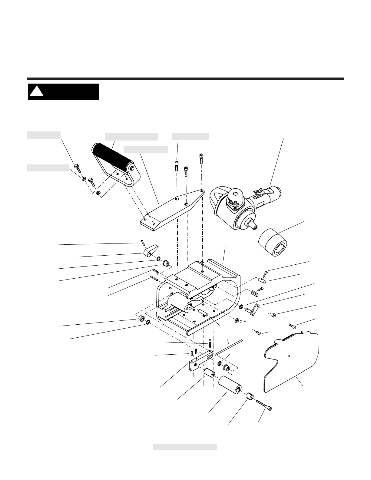
Dynabelter®Accu-Grinder
®
Always operate, inspect and maintain this tool in accordance with the Safety Code for portable air
tools (ANSI B186.1) and any other applicable safety codes and regulations. Please refer to
Dynabrade's Warning/Safety Operating Instructions for more complete safety information.
11548 Handle Assembly
95158 Bolt (2)
11544 Pressure Bar
95167 Washer (2)
95150 Screw (3)
11800 Housing
01845 Air Motor
(Includes 01794 Drive Wheel)
01794 Drive Wheel
95392 Screw (2)
11801 Motor Lock (2)
95226 O Ring
14056 Roller
11809 Tension Arm
95292 Screw
95422 Screw
40025 Button
95332 Pin
11831 Cover Guard
(Includes 11922
Contact Arm Jack)
11519 Bearing
95226 O-Ring
11804 Rod
95240 Roll Pin
11551 Belt Tension Lever
11519 Bearing
95236 Roll Pin
95216 Roll Pin
95226 O-Ring
11802 Bearing
95311 Screw
95231 Set Screw (2)
95226 O Ring
11805 Idler Wheel
11013 Bearing
95310 Screw
11806 Spacer
11803 Tension Arm
See Page 2 for 11961 Adjust-a-Wheel Contact Wheel Assembly and 11917 Rear Wheel Support.
See Page 3 for Important Operating, Safety and Maintenance Instructions before operating tool.
11705 Pressure Bar Assembly
!
WARNING
Page 2
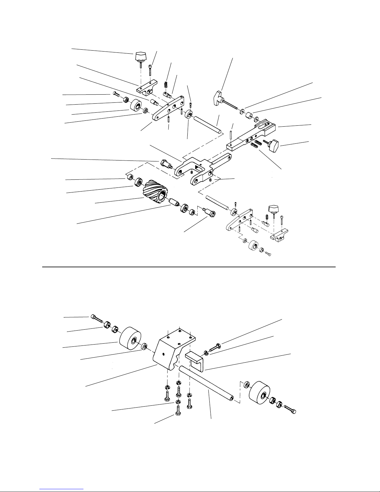
11807 Spacer
11912 Pressure Post (2)
95240 Pin (4)
11910 Shaft (2)
95420 Rough Adj. Knob (includes spacer and washer)
95339 Spring (2)
11913 Pressure Post (2)
95144 Screw (2)95232 Adj. Knob (2)
11915 Control Block (2)
11916 Guide Tire (2)
11016 Bearing (2)
95322 Screw (2)
11017 Spacer (2)
95149 Spring (2)
95323 Screw(2)
11850 Contact Wheel (90 Duro)
11813 Bearing (2)
11817 Bearing Spacer
11818 Spacer (2)
11815 Slotted Bolt
11816 Bolt
11812 Wheel Mount
11911 Collar (2)
11914 Tire Mount (2)
11961 Adjust-A-Wheel Contact Arm Assembly
95168 Screw (2)
95417 Washer (2)
95316 Pin
95232 Belt Tracking
Adj. Knob
11811 Contact Arm
95179 Screw
95158 Screw (4)
95156 Screw (2)
95167 Washer
11016 Bearing (4)
11017 Bearing Spacer(2)
11919 Clamp
11920 Axel
11918 Rear Wheel Support
95167 Washer (4)
11921 Wheel (2)
11917 Rear Wheel Support Assembly
2
(PD97•33)
Page 3

3
Important Operating, Maintenance and Safety Instructions
Carefully read all instructions before operating or servicing any Dynabrade® Abrasive Power Tool.
Warning: Hand, wrist and arm injury may result from repetitive work motion and overexposure to vibration.
Important: All Dynabrade air tools must be used with a Filter-Regulator-Lubricator to maintain all warranties.
Operating Instructions:
Warning: Eye, face and body protection must be worn while operating power tools. Failure to do so may result in serious injury or death. Follow safety
procedures posted in workplace.
1. With power source disconnected from tool, securely fasten abrasive/ accessory on tool.
2. Install air fitting into inlet bushing of tool. Important: Secure inlet bushing of tool with a wrench before attempting to install the air fitting to avoid damaging
valve body housing.
3. Connect power source to tool. Be careful not to depress throttle lever in the process.
4. Check tool speed with tachometer. If tool is operating at a higher speed than the RPM marked on the tool or operating improperly, the tool should be
serviced to correct the cause before use.
Maintenance Instructions:
1. Check tool speed regularly with a tachometer. If tool is operating at a higher speed than the RPM marked on the tool, the tool should be serviced to correct
the cause before use.
2. Some silencers on air tools may clog with use. Clean and replace as required.
3. All Dynabrade air motors should be lubricated. Dynabrade recommends one drop of air lube per minute for each 10 SCFM (example : if the tool
specification state 40 SCFM, set the drip rate of your filter-lubricator at 4 drops per minute). Dynabrade Air Lube (P/N 95842: 1pt. 473ml.) is recommended.
4. An air line filter-regulator-lubricator must be used with this air tool to maintain all warranties. Dynabrade recommends the following: 11299 Air Line Filter-
Regulator-Lubricator — Provides accurate air pressure regulation, two-stage filtration of water contaminants and micro-mist lubrication of pneumatic
components. Operates 100 CFM @ 100 PSI has 1/2" NPT female ports.
5. Use only genuine Dynabrade replacement parts. To reorder replacement parts, specify the Model #, Serial #, and RPM of your machine.
6. A motor tune-up kit (P/N 96259) is available which includes assorted parts to help maintain motor in peek operating condition.
7. Mineral spirits are recommended when cleaning the tool and parts. Do not clean tool or parts with any solvents or oils containing acids, esters, keytones,
chlorinated hydrocarbons or nitro carbons.
Safety Instructions:
Products offered by Dynabrade should not be converted or otherwise altered from original design without expressed written consent from
Dynabrade, Inc.
• Important: User of tool is responsible for following accepted safety codes such as those published by the American National Standards Institute (ANSI).
• Operate machine for one minute before application to workpiece to determine if machine is working properly and safely before work begins.
• Always disconnect power supply before changing abrasive/accessory or making machine adjustments.
• Inspect abrasives/accessories for damage or defects prior to installation on tools.
• Please refer to Dynabrade’s Warning/Safety Operating Instructions Tag (Reorder No. 95903) for more complete safety information.
• Warning: Hand, wrist and arm injury may result from repetitive work, motion and overexposure to vibration.
Notice
All Dynabrade motors use the highest quality parts and metals available and are machined to exacting tolerances. The failure of quality pneumatic motors can
most often be traced to an unclean air supply or the lack of lubrication. Air pressure easily forces dirt or water contained in the air supply into motor bearings
causing early failure. It often scores the cylinder walls and the rotor blades resulting in limited efficiency and power. Our warranty obligation is contingent upon
proper use of our tools and cannot apply to equipment which has been subjected to misuse such as unclean air, wet air or a lack of lubrication during the use of
this tool.
One Year Warranty
Following the reasonable assumption that any inherent defect which might prevail in a product will become apparent to the user within one year from
the date of purchase, all equipment of our manufacture is warranted against defects in workmanship and materials under normal use and service. We shall
repair or replace at our factory, any equipment or part thereof which shall, within one year after delivery to the original purchaser, indicate upon our
examination to have been defective. Our obligation is contingent upon proper use of Dynabrade tools in accordance with factory recommendations,
instructions and safety practices. It shall not apply to equipment which has been subject to misuse, negligence, accident or tampering in any way so as to affect
its normal performance. Normally wearable parts such as bearings, sanding pads, rotor blades, etc., are not covered under this warranty.
Machine Length Height Weight Abrasive Belt Size Air Flow Rate Sound Motor Motor Air Pressure
Number Inch (mm) Inch (mm) Pound (kg) Inch (mm) SCFM (LPM) Level HP (W) RPM PSI (Bars)
11450 20" (508) 9" (229) 18 lbs. (8.2) 2" (51) W x 30" (762) L 57 (1,614) 87 dBA 2.0 (1,491) 7,200 90 (6.2)
Additional specifications: Air Inlet Thread 1/2" (13 mm) NPT • Hose Size 1/2" (13 mm)
Page 4

Abrasive Belt/Contact Arm Change Instructions:
To Change Belt:
1. Disconnect power source. Remove 11831 Cover Guard and release 11551 Belt Tension Lever.
2. Loosen 95420 Rough Adjustment Knob. This will loosen contact arm assembly in housing track. Remove belt from contact arm and drive wheel.
3. Pull belt backwards and to the left until belt is released from drive wheel.
4. Install new belt by placing belt over contact wheel and drive wheel.
5. Using 11922 Tension Wrench, push contact arm forward until belt is tight. Tighten 95420 Knob to lock contact arm in place.
6. Reset 11551 Belt Tension Lever. Replace 11831 Cover Guard.
7. Connect power source and start motor.
8. Adjust belt tracking by turning 95232 Belt Tracking Knob on contact arm assembly to the left or right accordingly.
To Change Belt Contact Arm Assembly:
1. Disconnect power source. Remove 11831 Cover Guard.
2. Remove abrasive belt (see instructions).
3. Remove 95420 Rough Adjustment Knob.
4. Remove contact arm and replace with desired contact arm.
5. Replace 95420 Knob. Do not tighten knob at this point.
6. Replace abrasive belt (see instructions).
7. Using 11922 Tension Wrench, push contact arm assembly forward until the belt is tight. Tighten 95420 Knob and reset 11551 Belt Tension Lever.
8. Replace 11831 Cover Guard. Connect power source and start motor.
9. Adjust belt tracking by turning 95232 Belt Tracking Knob on contact arm assembly to the left or right accordingly.
Remove 11831 Cover Guard
11922 Tension Wrench
11961 Adjust-A-Wheel Contact Arm Assembly
11548 Handle Assembly
4
11851 Contact Wheel Assembly
11805 Idler Wheel
95232 Belt Tracking Knob
11961 Adjust-A-Wheel Contact Arm Assembly
11851 Contact Wheel Assembly
11805 Idler Wheel
01794 Drive Wheel
11922 Tension Wrench
Remove 11831 Cover Guard
01794 Drive Wheel
(PD97•33)
Page 5

5
Belt Size: 1" wide x 30" long.
11650 Contact Wheel: 2" diameter x 1" wide 70
durometer standard serrated urethane.
11605 Platen: 1" wide x 2-1/2" long. 7-1/2" workable reach.
11672 Contact Arm Assembly available; same as 11681
except with 90-duro contact wheel.
Note: The higher the durometer the harder the wheel.
Durometer Serration Color Part No.
90 Scoop Amber 11614
90 Standard Amber 11618
80 Standard Blue 11652
70 Standard Green 11650
Belt Size: 2" wide x 30" long.
11847 Contact Wheel: 2" diameter x 2" wide 70 durometer
standard serrated urethane.
Platen: Optional 11659 Platen Assembly is available for
mounting 2" wide x 2-1/2" long Dynapad platen; has 7"
workable reach. 11872 Contact Arm Assembly available;
same as 11870 except with 90-duro contact wheel.
Note: 2" diameter x 2" wide urethane wheel assemblies are
for extra heavy-duty machines only.
11681
2" Dia. x 1" W Urethane Wheel Assemblies
Available For 11681
Durometer Serration Color Part No.
90 Standard Amber 11851
70 Standard Green 11847
70 Scoop Green 11849
90 Scoop Amber 11853
2" Dia. x 2" W Urethane Wheel Assemblies
Available For 11870
Dynabelter®Contact Arms
• Grind, blend, polish welds; strap
polish using slack of belt.
• 7" workable reach.
Belt Size: 1" wide x 30" long.
11616 Contact Wheel: 1" dia. x 1" wide 80 durometer smooth rubber.
11605 Platen: 1" wide x 2-1/2" long.
• Grind, deburr, polish over
Dynapad platen.
• 7-1/2" workable reach.
11663
11668 Stroke Sander
11682
• Grind, deburr fillet welds,
inside corners.
• 7" workable reach.
Belt Size: 1/2" or 1" wide x 30" long.
11638 Contact Wheel: 4" dia. x 1/2" wide 70 durometer radiused rubber.
Platen: None
Belt Size: 1" wide x 30" long.
11642 Contact Wheel: 4" dia. x 5/8" wide 40 durometer serrated rubber.
(60, 80, 90 duro urethane wheels available). Platen: None
• Polish contours without gouging
workpiece.
• Ideal for stainless pipe.
• 7" workable reach.
11684
Belt Size: 1" wide x 30" long.
11616 Contact Wheels: Two 1" wide x 1" dia. 80 durometer smooth rubber.
11605 Platen: 1" wide x 1-7/8" long.
• Wheel mount pivots to maintain
surface contact.
• Work on broad areas, blend stainless.
• Leaves "in-line" scratch pattern.
• 6" workable reach.
11677
Belt Size: 1" wide x 30" long.
11620 Contact Wheel: 4" dia. x 1" wide 40 durometer smooth rubber,
(80 duro available). Platen: None.
For best results when ordering 11717 Contact Arm:
For Dynabelter Model 11475:
Add 11705 Pressure Bar Assembly and 11794 Back Wheel Assembly.
For Dynabelter Model 11476: Add 11544 Pressure Bar, three 95150
Mounting Screws and 11794 Back Wheel Assembly.
Belt Size: 1" wide x 30" long.
11618 Contact Wheel: 2" dia. x 1" w 90-durometer scoop serrated urethane.
Platen: None.
• Provides 9" workable reach. Grind off contact wheel; excellent for polishing off slack of belt.
• For use with extra heavy-duty models 11450 and 11477 only.
Belt Size: 2" wide x 34" long.
11902 Contact Wheel: 4" diameter x 2" wide 80-durometer scoop serrated urethane.
Platen: None.
11894
Twist Knobs (2)
11870
11717 Adjust-A-Wheel
Page 6

6
Disassembly/Assembly Instructions
Important: Manufacturer’s warranty is void if tool is disassembled before warranty expires.
A Motor Repair Kit (96259) is available which contains special tools for disassembly/assembly. Please refer to parts breakdown for part identification.
Tool Disassembly:
1. Disconnect tool from power source.
2. Remove back-up pad with a 24mm wrench.
3. Insert 01697 Inlet Bushing securely into vise.
4. Roll 07136 Handle Grip Back away from housing.
5. Remove 52495 Nut by using a 32mm wrench (P/N 96079).
6. Separate valve body from housing.
7. Remove 95720 Screws (4) and 01791 Washers (4) from 52461 Housing Cap. Remove housing cap and 52477 Gasket.
Motor Disassembly:
1. Grip onto governor cage assembly and pull motor assembly from housing.
Note: If motor assembly does not come out freely, gently tap tool rotor side down to "pop" motor from housing.
2. Remove governor cage assembly from 52466 Rotor (left hand thread).
3. Insert a tap pin into rear bearing plate and press the 52466 Rotor from the rear bearing plate.
4. Place motor assembly in softjaw vise.
5. Remove 01823 Washer and 01835 Shim from assembly.
6. Remove 01815 Rotor Nut with an adjustable wrench. Twist rotor nut from shaft.
7. Remove 52475 Cylinder, blades (4) and spacer from rotor.
8. Remove 52472 Front Bearing Plate , front bearing and shims from 52466 Rotor. Note: Bearing, front bearing plate and spacer are a slip fit into rotor.
9. Press 01036 Bearing from bearing plate.
Motor disassembly complete.
Motor Reassembly:
Important: Be certain all parts are cleaned and in good repair before reassembly.
1. Place 52466 Rotor in padded vise with threaded spindle facing upwards.
2. Slip 52467 Spacer onto rotor.
3. Place .002" shim into front bearing plate as initial spacing and slip 01825 Bearing into plate. Note: 52471 Shim Pak contains .001" and .003" shims.
4. Install bearing/bearing plate assembly onto rotor.
5. Install 01815 Rotor Nut onto assembly.
6. Tighten rotor nut onto rotor, torque 22.5 N•m/200 in. - lbs.
7. Check clearance between rotor and bearing plate by using a .001" feeler gauge. Clearance should be at .001" to .0015". Adjust clearance by repeating
steps 1-5 with different shims if necessary.
8. Once proper rotor/gap clearance is achieved, install well lubricated 52474 Blades (4) into rotor slots. Dynabrade Air Lube P/N 95842 (or equivalent) is
recommended for lubrication before installation in rotor slots.
9. Install cylinder over rotor.
10. Press the 01036 Rear Bearing into 52476 Rear Bearing Plate. Press bearing/bearing plate assembly onto rotor. Be sure that pin and air slot line-up
with pin hole and air inlet slot in cylinder.
11. Place the tool into a soft jaw vise and tighten the governor assembly (52478 Governor Cage) torque 9.0 N•m/80 in. - lbs. (left hand thread).
12. Place 01835 Shim and 01823 Washer into housing.
13. Install 52477 Gasket and 52461 Housing Cap with 95720 screws and 01791 Washers, tighten screws to 9 N•m/80 in. - lbs.
14. Place complete motor assembly into housing. Be sure motor drops all the way into housing.
15. Motor adjustment must now be checked. With motor housing still mounted in vise, pull end of rotor and twist (10-15 lbs. force), rotor should turn freely
without drag. If drag or rub is felt, then increase preload or remove shim. Also, push end of rotor and twist (10-15 lbs. force), rotor should turn freely
without drag. If drag or rub is felt, then deload or add a shim.
16. Apply 2 drops of #271 Loctite® (or equivalent) to threads of adjustment bushing before tightening.
17. Slip 52491 Bushing through 52495 Nut and packing, and secure into housing.
18. Tighten 52491 Adjustment Bushing into housing torque 50 N•m/ 450 in. - lbs. Tighten valve body into housing.
19. Secure inlet bushing into vise. Place 52495 Nut and 01746 O-Ring onto valve body. Swivel 52494 Valve Body to desired throttle lever position.
20. Tighten 52495 Nut to 45 N•m/400 in. - lbs. Roll 07136 Grip back into place.
Tool assembly is complete. Please allow 30 minutes for adhesives to cure before operating tool.
Important: Motor should now be tested for proper operation at 90 PSI. If motor does not operate properly or operates at a higher RPM than marked on the
tool, the tool should be serviced to correct the cause before use. Before operating, place 2-3 drops of Dynabrade Air Lube (P/N 95842) directly into air inlet
with throttle lever depressed. Operate tool for thirty seconds to determine if tool is operating properly and to allow lubricating oils to properly penetrate motor.
Loctite® is a registered trademark of Loctite Corp.
(PD97•33)
Page 7

7
01845 Air Motor
(Includes 01794 Drive Wheel)
01815 Rotor Nut
52446 Housing
01829 Governor Spring
52467 Spacer
01825 Bearing
52472 Bearing Plate
52173 Shim Pak
50548 Spring Holder
52476 Bearing Plate
01036 Bearing
52475 Cylinder
50511 Screw (2)
01791 Washer (2)
52461 Housing Cap
52165 Gasket
52180 Clamp
52164
Exhaust
Cover
01089 Lever
01697 Inlet Bushing
01017 Pin
52494 Valve Body
(Inc. 07142 Bushing)
07168 Valve Stem Assembly
07145 Spring
07146 Packing
07147 Plug
01746 “O” Ring
52491 Adj. Bushing
52495 Nut
52496 Packing07136 Handle Grip
52477 Gasket
50541 Governor Valve
52478 Governor Cage
96059 Governor Pin (2)
52466 Rotor
01791 Washer (4)
95720
Screw (4)
01673 Pin
KEY
L
T
O
Loctite/Hernon: L
2
= Loctite #271, L3= Loctite #380,
L
4
= Hernon #940
Torque: N•m x 8.85 = In. - lbs.
T
2
= 4.5 N•m, T3= 7 N•m, T4= 9 N•m, T5= 17 N•m,
T
6
= 22.5 N•m, T7= 45 N•m, T8= 50 N•m, T9= 56 N•m
G
Oil
Grease
T
7
L
2
L
3
T
8
L
2
T
5
T
2
01823 Washer
01835 Shim Packet
T
6
52471 Shim Pak
01672 Pin
T
4
52474
Blade (4/pkg.)
O
T
4
T
9
95375 O-Ring
94522 Muffler Cap
52498 Governor Weight (2)
50468 Pin
L
4
52166 Seal
Page 8

DYNABRADE
®
Toll Free (USA) 1-800-828-7333
Toll Free (Can.) 1-800-344-1488
DYNABRADE, INC., 8989 Sheridan Drive • Clarence, NY 14031-1490 • Phone: (716) 631-0100 • Fax: 716-631-2073 • International Fax: 716-631-2524
DYNABRADE EUROPE S.àr.l., Zone Artisanale • L-5485 Wormeldange—Haut, Luxembourg • Telephone: 352 76 84 94 • Fax: 352 76 84 95
© DYNABRADE, INC., 1997 PRINTED IN USA
Visit our new Web Site via Industry.Net MROP On-Line: http://www.dynabrade.industry.net E-Mail: DynaTalk@aol.com
 Loading...