

Page 1
Parts Page Reorder No. PD96•29
Effective May, 1996
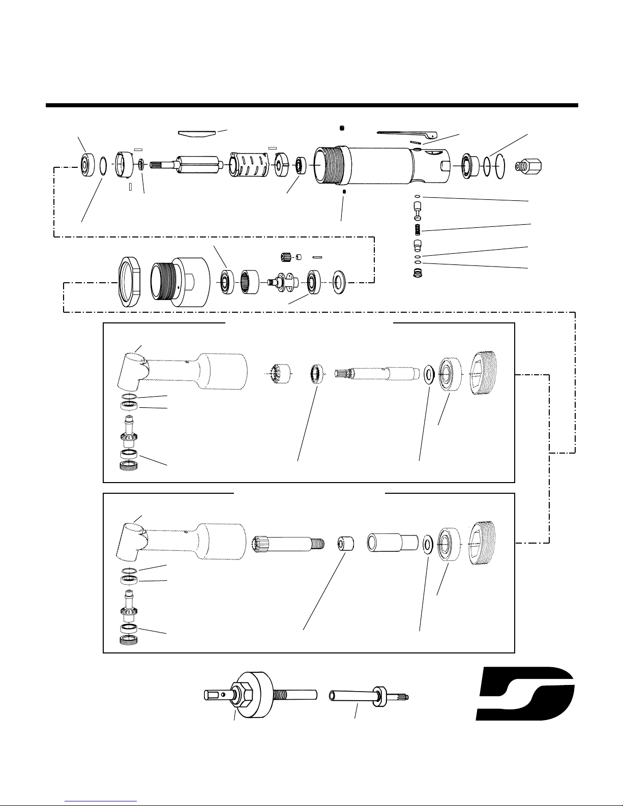
95809 Tune-Up Kit
For use with:
3,200 RPM Angle Head Tools
Parts included in kit are identified. See reverse side for Tune-up Instructions.
02649 Bearing
54514 Blades (5) (5/pkg.)
54515 Spacer
11016 Bearing
01017 Pin
01041 Grease Fitting
54523 O-Ring
54508 O-Ring
01022 Spring
01024 O-Ring
01025 O-Ring
54520 Bearing
54520 Bearing
54529 Shim Packet (as req.)
95398 Bearing
54545 Shim54542 Ball Bearing
54536 Shim
54542 Ball Bearing
01041 Grease Fitting
For Models succeeding serial number N24309
54537 Ball Bearing
95398 Ball Bearing
54529 Shim54531 Needle Bearing
54536 Shim
54534 Ball Bearing
01041 Grease Fitting
For Models prior to serial number N24309
54537 Ball Bearing
*54567 Spindle Puller
*54568 Spindle Wrench
*For use with models prior to S/N N24309 Only
®
DYNABRADE
Page 2

Tune-Up Instructions
Important: Manufactures warranty is void if tool is disassembled before warranty expires.
Refer to the appropriate parts page for additional part identification.
Motor Disassembly:
1. Secure tool in a soft jaw vise holding onto wrench flats on rear of motor housing.
2. Secure lock ring with a wrench and twist angle housing from motor housing (Note: Left hand threads).
3. Remove 54526 Adapter from motor housing and loosen 01040 Lock Screw.
4. Pull planetary gear assembly from motor housing. Pull motor from housing (if motor does not pull out freely, lightly tap end of housing with a rubber mallet).
5. Clamp a bearing separator between the 54522 Ring Gear of the planetary carrier assembly and front 54520 Bearing (nearest to spindle end of assembly).
Press bearing from carrier.
6. Remove ring gear and gears. Press rear 54520 Bearing from planetary carrier.
7. Press rotor from 02649 Bearing and front bearing plate. Remove 54515 Spacer, cylinder and 54514 Blades from rotor. Press 11016 Bearing from rear bearing plate.
8. Remove 54505 Plug from motor housing. Remove valve assembly.
9. Remove 95713 Inlet Adapter. Pry retaining ring from rear of housing and remove 54524 Muffler and 54523 O-Ring.
Motor disassembly complete.
Motor Reassembly:
Important: Be sure parts are clean and in good repair before reassembly. Follow all torque, grease and lubrication instructions.
1. Insert a .002" shim from 54529 Shim pack into front bearing plate.
2. Insert new 02649 Bearing into front bearing plate.
3. Place new 54515 Spacer onto pinion end of rotor. Make sure countersink faces rotor.
4. Press from bearing plate assembly onto rotor until tight against spacer.
5. Check clearance between rotor and bearing plate. Apply an outward (pulling) pressure on rotor. If rotor rubs bearing plate, reduce the spacing by removing shim or substitute
with .001" shim.
6. Insert new 54514 Blades (lubricate blades with Dynabrade Air Lube P/N 95842 or equivalent before installation).
7. Place cylinder over rotor. Be sure pin holes and air inlet holes align with holes in bearing plate.
8. Press new 11016 Bearing into rear bearing plate and press assembly onto rotor. Be sure pin holes and air holes line up with holes in cylinder.
9. Insert motor assembly into housing. The pin in front bearing plate should enter guide slot in housing wall.
10. Install 54517 Spacer with unrelieved face towards front bearing plate.
11. Press new 54520 Bearing onto front end of planetary carrier.
12. Replace gears, gear shafts and ring gear (notches face rear of carrier).
13. Press new 54520 Bearing onto carrier (there should be a slight drag between ring gear and bearings).
14. Install planetary assembly onto motor housing. Line-up notches in ring gear with hole in housing for lock screw.
15. Install lock screw until snug, then back off 1/2 turn.
16. Install 54526 Adapter onto motor housing.
17. Install new O-rings and spring stem assembly and replace into motor housing.
18. Install new 54523 O-Ring onto muffler and replace into housing. Replace snap ring and inlet adapter.
Motor reassembly complete.
Angle Head Assemblies:
1. Remove retaining nut from angle housing with 5/8" hex key.
2. Slide spindle assembly from housing and disassemble.
3. Remove bearing cap with pin wrench and remove work spindle assembly.
4. Install new 54542 Bearing and 54537 Bearing onto work spindle and insert into housing.
5. Install bearing cap and test for end play. Spindle should turn freely. If there is excessive end play, insert new 54536 Shim behind 54542 Bearing.
6. Reassemble spindle assembly using new 54542 Bearing, 95398 Bearing and 54545 Shim Pack (as required). Replace and tighten retaining nut.
7. Test for backlash between gears. There should be .002" to .003" Backlash. Adjust using 54545 Shim Pack.
Note: 54567 Spindle Puller and 54568 Spindle Wrench (or equivalent) required. These tools are not included with tune-up kit.
1. Remove retaining nut from angle housing with 5/8" hex key.
2. Insert 54568 Spindle wrench into spline adapter of spindle and unscrew.
3. Screw female threaded end of 54567 Spindle Puller onto gear spindle. Tighten puller ring until gear spindle and 54531 Needle Bearing are removed from angle housing.
4. Remove bearing cap with pin wrench and remove work spindle assembly.
5. Install new 54534 Bearing and 54537 Bearing onto work spindle and insert into housing.
6. Install bearing cap and test for end play. Spindle should turn freely. If there is excessive end play, insert new 54536 Shim behind 54534 Bearing.
7. Insert gear spindle into housing, make sure teeth line up.
8. Install new 54531 Needle Bearing into housing and onto gear spindle. Using bored end of 54568 Spindle Wrench, press 54531 Needle Bearing over gear spindle down to gear.
9. Line up hole in housing with hole in gear spindle and lock together using a 3mm pin.
10. Install 95398 Bearing onto spline adapter and using 54568 Spline Wrench, tighten spline adapter onto gear spindle.
11. Replace and tighten retaining nut.
12. Test for backlash between gears. There should be .002" to .003" backlash. Adjust using 54529 Shim Pack.
Reattach angle housing to motor housing and secure with lock ring.
Motor should operate at 3,200 RPM at 90 PSI (6.2 Bar). RPM should be checked with a tachometer. If machine is running at a higher RPM then the tool should be serviced to
correct the cause before use. Before operating, Dynabrade recommends that 2-3 drops of pneumatic tool oil be placed directly into air inlet with throttle lever depressed and that
the gears be be greased through the grease fitting located on the motor and angle housings.
For models succeeding S/N N24309.
For models prior to S/N N24309.
Page 3
See inside for Important Operating, Maintenance and Safety Instructions.
Parts Page Reorder No. PD94•31
Model:
50046 — Angle-Head Kit
54002 — Mini-Dynorbital Sander
54003 — Mini-Dynorbital Sander
50223 — 2" Disc Sander
51091 — Die Grinder
53026 — Drill
50047 — 3" Buffer
50070 — Finesse Sanding Kit
Effective April, 1994
Always operate, inspect and maintain this tool in accordance with the Safety Code for portable air tools
(ANSI B186.1) and any other applicable safety codes and regulations. Please refer to Dynabrade's
Warning/Safety Operating Instructions for more complete safety information.
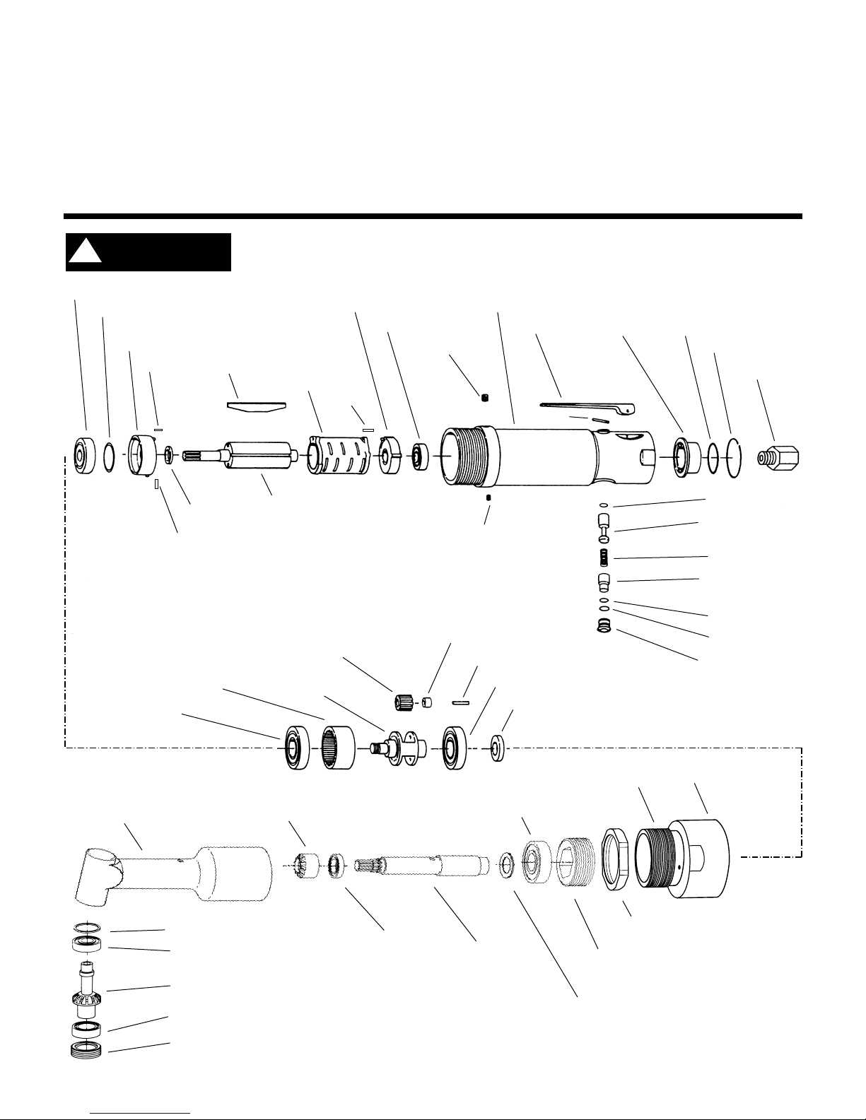
Machine and Motor Parts
For Serial Number N24309 and Higher
3,200 RPM Angle-Head
54512 Cylinder
01041 Grease Fitting
02649 Bearing
54529 Shim Packet (as req.)
54514 Blades (5) (5/pkg.)
54516 Bearing Plate
(Incl. 01009 Pin and 01042 Pin)
54511 Bearing Plate
(Incl. 01009 Pin)
11016 Bearing
01040 Lock Screw
01009 Pin
01009 Pin
01042 Pin
54515 Spacer
54513 Rotor (Incl. 54515 Spacer)
54519 Gear (2)
(Incl. 01033 Needle Bearings)
54509 Housing
(Incl. 54510 Valve Bushing, 01041 Grease Fitting)
01016 Lever 54524 Muffler
95713 Adapter
54508 “O” Ring
01022 Spring
01024 “O” Ring
54506 Regulator
(Incl. 01024 “O” Ring)
01025 “O” Ring
54526 Adapter
(right hand threads)
(left hand threads)
54527 Lock Ring
(left hand threads)
54540 Retaining Nut
(left hand threads)
01053 Bearing
54541 Spindle
54542 Ball Bearing
54545 Shim Pack (as req.)
54546 Bevel Gear
54547 Housing
54536 Shim Pack (as req.)
54542 Ball Bearing
54537 Ball Bearing
54550 Bearing Cap (left hand threads)
54549 Work Spindle
54505 Plug
(Incl. 01025 “O” Ring)
54507 Valve Stem
(Incl. 54508 “O” Ring)
54523 “O” Ring
54525 Retaining Ring
01017 Pin
54517 Spacer
54520 Bearing
54518 Shaft (2)
01033 Needle Bearing (2)
54521 Carrier
54522 Ring Gear
54520 Bearing
!
WARNING
Page 4

Important Operating, Maintenance and Safety Instructions
Carefully read all instructions before operating or servicing any Dynabrade®Abrasive Power Tool.
Warning: Hand, wrist and arm injury may result from repetitive work motion and overexposure to vibration.
Important: All Dynabrade air tools must be used with a Filter-Regulator-Lubricator to maintain all warranties.
Operating Instructions:
Warning: Eye, face and body protection must be worn while operating power tools. Failure to do so may result in
serious injury or death. Follow safety procedures posted in workplace.
1. With power source disconnected from tool, securely fasten abrasive/accessory on tool.
2. Connect power source to tool. Be careful not to depress throttle lever in the process.
3. Check tool speed with tachometer. If tool is operating at a higher speed than the RPM marked on the tool or
operating improperly, the tool should be serviced to correct the cause before use.
Maintenance Instructions:
Products offered by Dynabrade should not be converted or otherwise altered from original design without
the expressed written consent from Dynabrade, Inc..
1. Check tool speed regularly with a tachometer. If tool is operating at a higher speed than the RPM marked on the
tool, the tool should be serviced to correct the cause before use.
2. Some silencers on air tools may clog with use. Clean and replace as required.
3. All Dynabrade air motors should be lubricated with two drops of Dynabrade Air Lube (P/N 95842: 1pt. 473ml.)
every four hours of use.
4. An air line filter-regulator-lubricator must be used with this air tool to maintain all warranties. Dynabrade
recommends the following:
11289 Air Line Filter- Regulator-Lubricator — Provides accurate air pressure regulation, two-stage filtration of
water contaminants and micro-mist lubrication of pneumatic components. Operates 28 CFM @ 90 PSI has
3/8" NPT female ports.
5. Gear case of this Dynabrade air tool should be lubricated every 16 hours of use by using 95541 Grease Gun
and 95542 Grease.
Safety Instructions:
• Important: User of tool is responsible for following accepted safety codes such as those published by the American
National Standards Institute (ANSI).
• Operate machine for one minute before application to workpiece to determine if machine is working properly and
safely before work begins.
• Always disconnect power supply before changing abrasive/accessory or making machine adjustments.
• Inspect abrasives/accessory for damage or defects prior to installation on tools.
• Please refer to Dynabrade’s Warning/Safety Operating Instructions Tag (Reorder No. 95903) for more complete
safety information.
• Warning: Hand, wrist and arm injury may result from repetitive work, motion and overexposure to vibration.
One Year Warranty
Following the reasonable assumption that any inherent defect which might prevail in a product will become apparent
to the user within one year from the date of purchase, all equipment of our manufacture is warranted against defects
in workmanship and materials under normal use and service. We shall repair or replace at our factory, any
equipment or part thereof which shall, within one year after delivery to the original purchaser, indicate upon our
examination to have been defective.
Our obligation is contingent upon proper use of Dynabrade tools in accordance with factory recommendations,
instructions and safety practices. It shall not apply to equipment which has been subject to misuse, negligence,
accident or tampering in any way so as to affect its normal performance.
Normally wearable parts such as bearings, sanding pads, rotor blades, etc., are not covered under this warranty.
2
Page 5

3
Assembly/Disassembly Instructions
3,200 RPM Angle Head Tools
A complete motor tune-up kit, Part No. 95809, is available which includes assorted parts to help maintain
motor in tip-top shape.
Warning: Manufacturers warranty is void if tool is dissembled before warranty expires.
To Disassemble Angle-Head Tool:
1. Carefully place motor housing in a soft jaw vise, holding it on the flats at the air inlet end of the housing.
2. Use two wrenches, place one on 54527 Lock Ring, and the other on 54547 Angle-Head Housing. Turn 54547
Housing in a clockwise direction. (Note: left hand thread).
To Remove Planetary Gear and Motor Assembly:
1. Loosen 54526 Adapter turning it counter clockwise.
2. Loosen 01040 Lock Screw and remove.
3. Pull out planetary gear assembly. Motor is now free to slide out of housing. (Note: If motor does not slide out
freely, tap end of housing with plastic mallet).
To Disassemble Planetary Gear Assembly:
1. Clamp a bearing separator between the 54522 Ring Gear and the 54520 Bearing toward the spline end of the assembly.
2. Hang the planetary assembly with the separator in an arbor press (Note: spline end pointing up) and press
bearing from 54521 Carrier.
3. Remove 54522 Ring Gear and both 54519 Gears along with 54518 Shafts. Normally 01033 Needle Bearings
inside 54519 Gears will last the life of the gears. Replacement gears have needle bearings already pressed in.
If it is desired to replace needle bearings in gears, pusher rod must be .249 minus .005 inches in diameter. When
pressing new needle bearings into gears, press only on the trademark end of bearings.
4. Press remaining 54520 Bearing from 54521 Carrier.
To Disassemble Motor:
1. Clamp a bearing separator between the 54516 Bearing Plate and the 54512 Cylinder.
2. Hang the motor assembly with the separator in an arbor press (Note: gear end pointing up) and press bearing
from 54513 Rotor.
3. 54516 Front Bearing Plate and 02649 Bearing can now be pressed off.
4. Press 54511 Bearing Plate and 11016 Bearing from 54313 Rotor.
To Disassemble Angle-Head Assembly:
1. Remove 54540 Retaining Ring using a standard 5/8" hex key (Note: retaining ring has a left hand thread).
2. 54541 Spindle and associated parts will now slide out of 54547 Housing.
3. Loosen 54550 Bearing Cap, using a standard pin wrench or other suitable tools.
4. Pull out 54549 Work Spindle and associated parts.
Disassembly is complete.
To Assemble Angle-Head Assembly:
(Note: All parts should be thoroughly cleaned before reassembly).
1. Assemble 54542 Ball Bearing and 54537 Ball Bearing to 54549 Spindle. Insert assembly into small cavity of angle-head.
2. Screw in 54550 Lock Ring and test for end-play. Spindle must turn freely, but there should not be excessive end-
play. If end-play is excessive, insert 54536 Shims as needed in 54547 Angle Housing behind 54542 Ball Bearing.
3. Slip 54542 Bearing, 54546 Bevel Gear onto 54541 Spindle.
4. Place 54545 Shim Pack (as req.) onto spindle and install 01053 Bearing onto 54541 Spindle.
5. Use a standard 5/8" hex key to install 54540 Retaining Ring (Note: left hand thread) in 54547 Angle Housing
“finger tight”.
6. Test for backlash between gears. There should be .002 to .003 backlash between the gears. If assembly does not
have proper backlash, remove 54540 Retaining Ring and 01053 Ball Bearing. Place necessary 54545 Shims on
bearing seat of 54541 Spindle. Replace 01053 Ball Bearing and 54540 Retaining Ring. When proper backlash is
set, tighten 54540 Retaining Ring with standard 5/8" hex key and recheck for backlash.
continued on next page
Page 6

Assembly/Disassembly Instructions
(continued)
3,200 RPM Angle Head Tools
To Assemble Motor:
1. Press a 01009 Pin into face of 54511 Bearing Plate and 54516 Bearing Plate and Press 01042 Pin in outer
diameter of 54516 Front Bearing Plate.
2. To correct for bearing tolerances, it is necessary to use 54529 Shim Pack (as req.) to maintain correct clearance
between ends of rotor and bearing plates.
3. Insert .002 Shim in 54516 Front Bearing Plate.
4. Insert 02649 Bearing into 54516 Bearing Plate.
5. Assemble 54515 Spacer onto pinion end of 54513 Rotor, making sure that the countersink faces the rotor.
6. Assemble 54516 Front Bearing Plate onto rotor by pressing on the inner race of 02649 Bearing and by supporting
rotor on opposite end. Be sure that bearing is pressed tight against 54515 Spacer.
7. Hold rotor in left hand and the bearing plate in right hand. Apply an outward (pulling) pressure and observe
spacing between end of rotor and bearing plate. This should be from flush (not rubbing) to .002 maximum. If the
rotor rubs the bearing plate, reduce the spacing between the bearing and the bearing plate by removing the .002
shim entirely, or by substituting a .001 shim for the .002 shim. However, if there is more than .002 spacing
between the end of the rotor and bearing plate, add .001 shim between the bearing and the bearing plate.
8. Assemble 54512 Cylinder so that inlet part will align with inlet holes in 54511 Rear Bearing Plate. The cylinder
exhaust slots must align with the slots in the bearing plate.
9. Insert 54514 Blades (lubricate blades with Dynabrade Air Lube P/N 95842 or equivalent prior to installation).
10. Support assembly squarely on the pinion end of rotor. Place 11016 Bearing in 54511 Rear Bearing Plate and
press onto rotor, pressing on the inner race of 11016 Bearing, just enough to bring the bearing plate against the
cylinder. There should be a slight drag between the bearing plates and cylinder when these are moved with the
fingers. Position cylinder until motor turns “finger free”.
To Assemble Motor in Housing:
(Note: Be sure that 01040 Lock Screw has been removed from motor housing).
1. Insert motor into 54509 Housing, making sure that 01042 Pin in 54516 Front Bearing Plate enters into slot cut into housing.
2. Insert 54517 Spacer with unrelieved face toward 54516 Front Bearing Plate.
To Assemble Planetary Assembly:
1. Press 54520 Bearing onto front end of 54521 Carrier until it seats.
2. Make sure that assembled 01033 Needle Bearing and 54519 Gears are lined up with hole and slide 54518 Shafts
into 54521 Carrier and 54519 Gears until end of shaft is flush with carrier face.
3. Place 54522 Gear, notches are to face rear end of the 54521 Carrier.
4. Press 54520 Bearing onto 54521 Carrier until there is a slight drag between the ring gear and the two bearings.
To Install Planetary Assembly in Housing:
1. Insert planetary assembly into motor housing, keeping notches in ring gear lined up with threaded hole for 01040 Lock Screw.
2. Thread lock screw into 54509 Motor Housing. Turn lock screw down until snug. Then back off 1/2 turn.
3. Thread 54526 Adapter onto 54509 Motor Housing.
To Assemble Angle-Head Assembly to Planetary Motor Assembly:
1. Assemble by screwing 54547 Angle Housing onto 54526 Adapter with 54527 Lock Ring.
2. Adjust and make certain that spline in 54541 Carrier is properly inserted into spline in 54541 Spline Spindle. Test
assembly at reduced speed, and secure assemblies with 54527 Lock Ring.
Tool assembly is complete
Note: Motor should operate at 3,200 RPM at 6.2 bar (90 PSI). RPM should be checked with a tachometer. Before operating, we recommend
that 2-3 drops of pneumatic tool oil be placed directly into the air inlet with throttle lever depressed. Grease gears through grease fittings.
Important
The regular maintenance of any air tool will contribute to greater efficiency of tool and will prolong tool life. The failure of quality
pneumatic air motors can most often be traced to an unclean air supply or the lack of lubrication. Air pressure easily forces dirt or water
contained in the air supply into motor bearings causing early failure. It often scores the cylinder walls and the rotor blades resulting in
limited efficiency and power. Frequent drainage of water traps in air lines is recommended. Each tool on each drop should also be
equipped with a secondary air processing unit. This consists of an in-line Filter-Regulator-Lubricator. All Dynabrade air tools must be
used with a Filter-Regulator-Lubricator to maintain all warranties. Our warranty obligation is contingent upon proper use of our tools and
cannot apply to equipment which has been subject to misuse such as unclean air, wet air or a lack of lubrication during the use of the tool.
Notice: Manufacturer’s warranty is void if tool is disassembled before warranty expires.
4
Page 7

Accessories
Mini-Dynorbital®Sanding Heads
Mini-Dynorbital®Sanding Pads
95809 Motor Tune-Up Kit:
Includes assorted parts to
help maintain motor in tiptop shape.
95987 – 5/16" open-end
(mates to tool spindle).
54585
Side Handle Assembly
Random Orbital Sanding Heads
54028: with 1/4"-28 Male Thread (Standard on tool Model 54002)
• Accepts 3" and smaller dia. sanding pads with 1/4"-20 female thread.
• With stud removed, 1/4"-20 male thread pad may be mounted.
54029: with 1/4"-28 Male Thread (Standard on tool Model 54003)
• Accepts 3" and smaller dia. sanding pads with 1/4"-20 male locking-
type thread such as 3M Roloc
®
.
54028
1/4"-28
Male thread
removable
1/4"-20 Stud
1/4"-28
thread
female locking-
type thread
female thread
locking-type
54029
54030: Rotary Sanding Head
• Accepts 3" and smaller diameter
sanding pads with male locking-type
threads such as 3M Roloc.
Roloc is a registered trademark of 3M Company.
54030
54021 Adapter
• Length: 1-3/16", Wrench Flats: 14mm.
• 1/4"-20 male thread, 1/4"-28 male thread.
• Standard with 50223 Disc Sander.
50055: 1/4" Collet
• 1/4"-28 male thread.
• Standard on 51091 Die Grinder.
5
1/4" sponge
vinyl face
1/4" sponge
60 duro rubber
Note: All Pads have a 5,000 RPM maximum. To mount pads that have 1/4"-20 female
thread directly to tool for conventional rotary action, use 54021 Adapter.
1/4"-20
female thread
For use with 54030 Sanding Head.
Order vinyl face pads
54091 or 54092 for wet
sanding operations.
For use with
non-woven nylon discs.
foam facing
sponge
locking-type
male thread
54017 3/4" Medium/Rubber 1/4"-20 Female For PSA Discs
54018 1-1/4" Medium/Rubber 1/4"-20 Female For PSA Discs
54031 1-1/4" Soft Locking-Type For PSA Discs
54087 3/4" Soft /Vinyl 1/4"-20 Female For PSA Discs
54088 1-1/4" Soft/Vinyl 1/4"-20 Female For PSA Discs
54089 3/4" Hook ‘n Loop 1/4"-20 Female
Non-Woven Nylon Discs
54090 1-1/4" Hook ‘n Loop 1/4"-20 Female
Non-Woven Nylon Discs
54091 3/4" Medium/Vinyl 1/4"-20 Female For PSA Discs
54092 1-1/4" Medium/Vinyl 1/4"-20 Female For PSA Discs
Part Pad Description/ Thread
No. Dia. Face Type Comments
“Soft” Density
“Medium” Dual-Density
“Hook ’n Loop”
“Soft” Locking-Type
1/4"-20
female thread
Page 8

DYNABRADE
®
Accessories (continued)
Sanding Pads for Disc Sanders
3" Diameter Hook Face Pads
3" Diameter Polishing Buffs
• 1/4"-20 Female Thread.
• 20,000 RPM max.
• Accepts 2" PSA discs.
• Standard on 50223 Angle-Head
Sander, with 54021 Mounting Adapter.
50107: 2" Diameter Pad
50112: 1/4"-20 female thread,
medium density, 15,000 RPM max.
50115: 1/4"-20 female thread,
hard density, 20,000 RPM max.
3" Diameter Pad
For locking-type discs
Terry Cloth Synthetic Wool Foam Waffle
50120: Foam Backing (Standard with 50047–3" Buffer)
50125: Rigid Backing
• Accepts reattachable abrasive discs as
well as polishing buff pads.
• 5,000 RPM maximum.
• 1/4"-20 female thread.
90030: Foam Waffle
90027: Terry Cloth
90028: Synthetic Wool
• Scrim back.
• Mount to 50120 or 50125 Hook Face Pads
Rigid
Backing
Foam
Backing
Discover other shop supplies & consumables on our website.
 Loading...