

Page 1
Parts Page Reorder No. PD97•41
Effective July, 1997
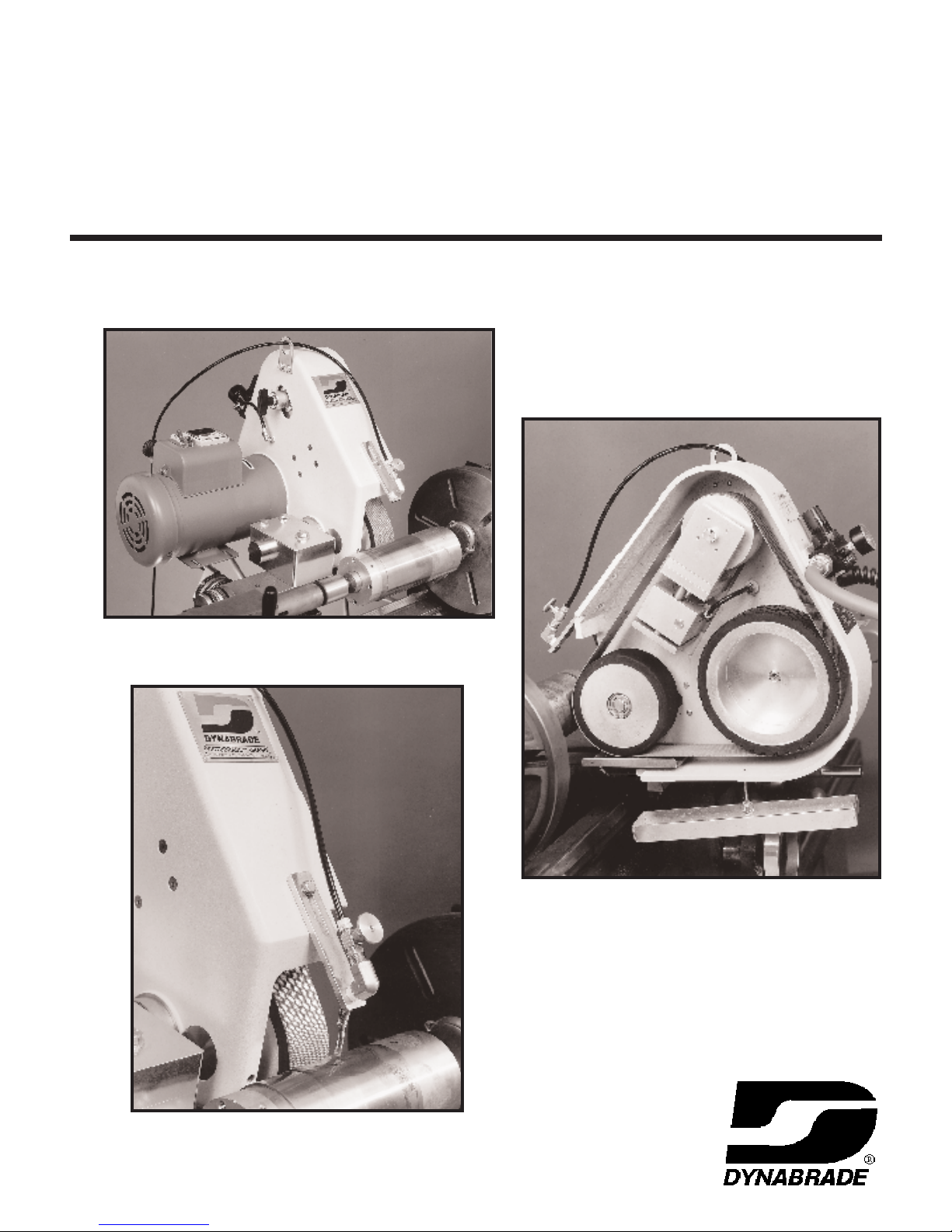
Precision Tool Post Grinder
:
Models
65750 – 3,450 RPM (Wet), 60 Hz
65751 – 2,850 RPM (Wet), 50 Hz
:
Instruction Manual
2" Wide x 48" Long Abrasive Belt Machine
Page 2
WARRANTY
ollowing the reasonable assumption that any inherent defect which might prevail in a product will become apparent
F
to the user within one year from the date of purchase, all equipment of our manufacture is warranted against defects
in workmanship and materials under normal use and service. We shall repair or replace at our factory, any equipment
or part thereof which shall, within one year after delivery to the original purchaser, indicate upon our examination to
have been defective.
Our obligation is contingent upon proper use of Dynabrade tools in accordance with factory recommendations,
nstructions and safety practices. It shall not apply to equipment which has been subject to misuse, negligence,
i
accident or tampering in any way so as to affect its normal performance.
Normally wearable parts such as bearings, contact wheels, rotor blades, etc., are not covered under this warranty.
ELECTRICAL WARNING
Warning: This tool does “not” come equipped with overcurrent protection. It is the user’s responsibility to provide an
adequately grounded circuit with correctly rated fuse or circuit breaker. A “ground-fault” protected device is also
recommended if tool is to be operated “wet”.
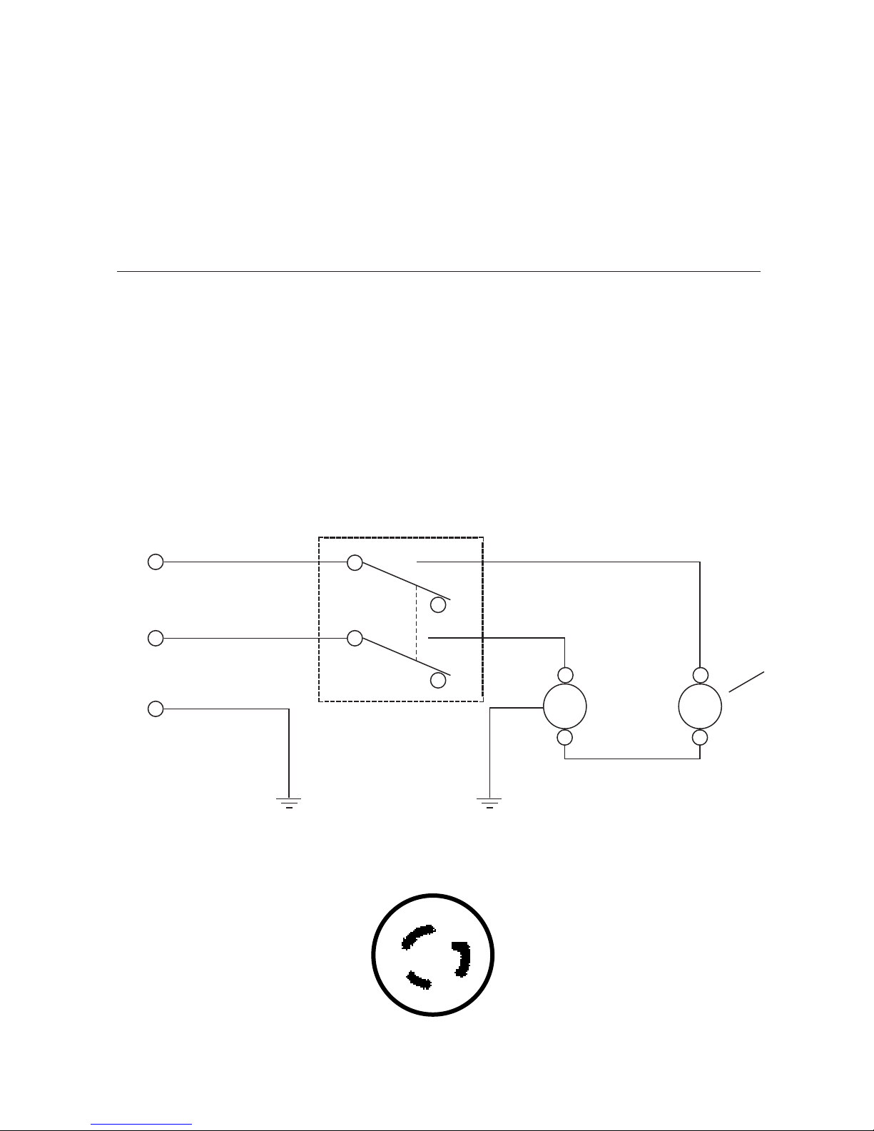
Refer to
and the supply circuitry is in accordance with local electrical codes and ordinances.
The machine “as shipped” is intended to be used exclusively on a 230-volt, Single Phase power supply.
Always disconnect tool from power at plug before performing any maintenance tasks.
Electrical Schematic ES-65014 for machine wiring. A qualified electrician can determine if the tool (as shipped)
230 V
1 Phase
60 Hz
Electrical Schematic ES-65014
DPST
Nema Configuration
Locking Type Plug
M
OPT.
A
X
G
V
L6 – 2OP
2
Page 3
MOUNTING INSTRUCTIONS
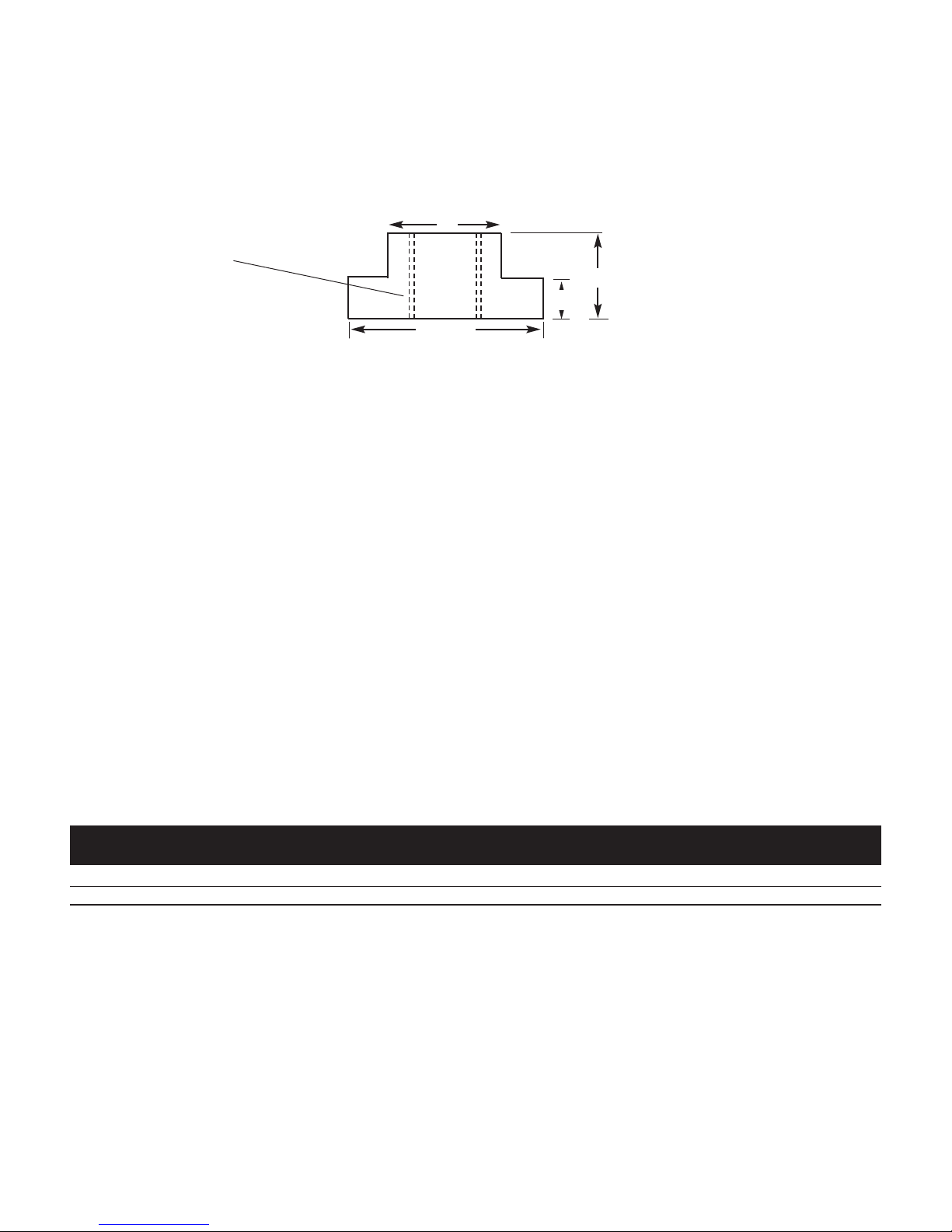
This machine comes with a “T”-nut and hex head screw for mounting directly to the lathe compound. Due to the many
lathe types, it may be necessary to alter or replace the “T”-nut with one of the correct size for the particular lathe.
“T”-nut dimensions are supplied as follows...
1"
1/2-13 UNC – 2B
Tapped Hole
3/4"
3/8"
1-3/4"
Mat’l 303-SS
MOUNTING:
STEP 1. - Remove any tooling, tooling holders, etc. from the lathe compound.
STEP 2. - Clear all chips and debris from the top of compound and “T”-slot.
STEP 3. - Providing the “T”-nut is of correct size for the lathe compound, lift (or hoist) the entire tool into position.
Align and insert “T”-nut into slot.
STEP 4. - Using your fingers, lightly snug the hex screw (P/N 97087) until the tool becomes parallel to the
workpiece centerline.
STEP 5. - The tool can now be swung from side to side and positioned for the desired angle between the contact
wheel and the workpiece. Once this is achieved, firmly tighten hex screw (P/N 97087).
STEP 6. - Position the contact wheel at or above the workpiece centerline. This will ensure proper belt tracking and
prevent chatter from occurring. The position can be altered by loosening the two cap screws (P/N 97088)
and allowing the tool to pivot on the pivot shaft (P/N 65266)
this task!) Firmly retighten the screws once proper positioning is achieved.
The machine is now ready for operation.
(tool must be supported while performing
Machine Specifications
Machine Width Length Height Machine Abrasive Motor
Model No. Inch (mm) Inch (mm) Inch (mm) Weight (kg) Belt Size Electrical RPM SFPM
65750 (Wet) 17" (432) 19" (483) 18" (457) 108 lbs. (49) 2"(50) x 48"(1219) 240 V/ 1 Ph/60 Hz 3,450 7,200 (2,187)
65751 (Wet) 17" (432) 19" (483) 18" (457) 108 lbs. (49) 2"(50) x 48"(1219) 240 V/ 1 Ph/50 Hz 2,850 6,000 (1,822)
3
Page 4

Item Part No. Description Qty.
1 66605 Housing 1
2
66608 Electric Assembly (50 Hz) 1
66607 Electric Assembly (60 Hz) 1
3 98378 Ammeter 1
4 98371 Switch 1
5 98370 Switch Guard 1
6 65195 Mounting Block 1
7 98493 T-Nut 1
8 65266 Pivot Bar 1
9 14333 Lift Bracket 1
10 66616 Tension Block 1
11 95696 Gauge 1
12 66617 Drive Wheel (2,850 RPM) 1
13 66614 Contact Wheel Shaft 1
14 97026 Screw 2
15 66622 Spacer Block 1
16 Reserved
17 65263 Tray (includes rod) 1
18 97773 Knob 1
19 65314 Tray Support 1
20 97061 Screw 2
21 66618 Cover 1
22 97760 Door Latch 1
23 97053 Screw 2
24 95179 Hex Screw 2
25 95167 Lock Washer 2
26 97088 Hex Screw 2
27 95183 Flat Washer 2
28 97057 Cap Screw 4
29 97059 Cap Screw 4
30 97087 Hex Screw 1
31 97310 Flat Washer 1
32 97085 Flathead Screw 4
33 97460 Key 1
34 97069 Carriage Bolt 2
35 97806 Air Cylinder 1
36 97112 Set Screw 1
37 97828 Fitting 2
38 97829 Hose 1 Ft.
39 97083 Flathead Screw 4
40 65232 Tension Strap 1
41 97883 Breather Vent 1
42 97894-B Valve 1
43 97898-C Regulator 1
44 97812 Oil Seal 4
45 65217 Bushing 4
46 66619 Contact Wheel 1
47 66611 Tension Shaft 2
48 Reserved 2
49 Reserved 4
50 97015 Cap Screw 4
51 65269 Tension Support 1
52 95202 Set Screw 3
53 97549 Bushing 2
54 97405 Roll Pin 2
55 66613 Idler Support 2
56 66615 Tracking Wheel (3,450 RPM) 1
57 97548 Ball Bearing 4
58 97442 Retaining Ring 3
59 66612 Tracking Shaft 1
60 65132 Tracking Hub 1
61 97152 Low Head Screw 4
62 95417 Nylon Washer 2
63 95186 Hex Nut 1
64 95314 Knob 1
65 65264 Drip Pan 1
66 95166 Flat Washer 1
67 95167 Lock Washer 1
68 95170 Wing Nut 1
69 97151 Eye Screw 1
70 65262 Nozzle Support 1
71 95761 Valve 1
72 95084 Reducer 1
73 96063 Elbow 1
74 97213 Nut 1
75 97827 Fitting 1
65750 –3,450 RPM (Wet), 60Hz
65751 –2,850 RPM (Wet), 50Hz
Precision Tool Post Grinder – Machine Parts Breakdown – Models 65750 and 65751
17
19
20
18
3
33
24
25
4
2
26
30
31
6
7
8
28
24
24
65
66
74
75
66 67 68 69
71
70
72
73
36
13
44
45
40
39
38
58
39
50
57
46
12
52
61
60
63
59
53
54
58
56
57
55
54
53
21
22
51
47
44
45
10
62
64
1
11
23
32
9
29
27
5
14
42
43
41
37
38
23
23
34
37
35
15
52
Page 5

MACHINE ADJUSTMENTS
Belt Change/Installation:
. Remove Belt Guard by grasping door latch
1
(P/N 97760) and rotate 1/4 turn counter-clockwise.
2. Turn off air supply at valve (item #42). This will retract air
ylinder (item #35) and thus removes tension from the belt.
c
3. Remove and replace belt.
4. Important: With hands clear from moving parts, turn air supply
back on at item #42. Regulator pressure should be set to 90 PSI
for proper belt tensioning.
5. "Jog" motor by turning on momentarily to ensure proper belt
tracking. Tracking procedure is described below.
Replace belt guard and turn door latch 1/4 turn clockwise until
“click” is heard.
Belt Tracking:
Belt tracking is accomplished by turning the tracking knob (P/N
95314). Turning clockwise moves belt to the right. Turning
counter-clockwise moves belt to the left.
Coolant Nozzle:
The coolant nozzle can be extended or retracted (if dia. allows) for good placement of coolant flow by loosening hex
screw (P/N 95179). Retighten once placement is achieved. The coolant nozzle has an adjustable flow valve which
connects to 1/4" diameter flexible nylon tubing.
Drip Pan:
The drip pan is hinged on a #10 eye screw and can be tilted fore and aft to direct coolant toward lathe bed.
Catch Tray Assembly:
Each machine comes equipped with an adjustable catch tray which positions underneath the contact wheel. Its
purpose is to collect the major portion of grind dust/swarf and direct it away from the lathe ways. It should be placed
within 1/8" of workpiece. Position can be changed by loosening knob (P/N 97773). When grinding into a shoulder, it
will be necessary to remove tray entirely.
MAINTENANCE
The grinders described in this manual have been designed to be maintenance-free. All bearings and moving parts
are sealed/shielded and lubricated for life. Electric motor maintenance should be performed as recommended by the
motor manufacturer.
Good housekeeping is essential to insuring long life of an
inspected for any wear, the machine will provide many years of quality service.
y machine tool.
By keeping the machine clean and visually
iodically inspect the contact wheels
er
P
parts early enough will prevent other parts from becoming damaged.
, idler rolls and dr
e pulley for any signs of wear. Repairing or replacing worn
iv
6
Page 6

ELECTRICAL SAFETY INSTRUCTIONS
Warning: When using electric tools, basic safety precautions should always be followed to reduce the
risk of a fire, electric shock, and personal injury, including the following:
1. Keep work area clean. Cluttered areas and benches invite accidents.
2. Consider work area environment. Keep work area well lit. Do not use tools in the presence of flammable
liquids or gases.
3. Guard against electric shock. Prevent body contact with grounded surfaces. For example; pipes, radiators,
ranges, refrigerator enclosures.
4. Keep children away. Do not let visitors contact tool or extension cord. All visitors should be kept away from work area.
5. Do not force tool. It will do the job better and safer at the rate for which it was intended.
6. Use the right tool. Do not force a small tool or attachment to do the job of a heavy duty tool. Do not use tool for
purposes not intended.
7. Dress properly. Do not wear loose fitting clothing or jewelry. They can be caught in moving parts. Rubber gloves and
non-skid footwear are recommended when working outdoors. Wear protective hair covering to contain long hair.
8. Use safety glasses. Also use face-shield or dust mask if operation area is dusty.
9. Do not abuse cord. Never carry tool by cord or yank it to disconnect from receptacle. Keep cord from heat, oil
and sharp edges.
10. Secure work. Use clamps or a vice to hold workpiece. It’s safer than using your hand and it frees up both
hands to operate tool.
11. Do not overreach. Keep proper footing and balance at all times.
12. Maintain tools with care. Keep tools clean for better use and safer performance. Follow instructions for
lubricating and changing accessories. Inspect tool cords periodically and if damaged, have repaired by
authorized service facility. Inspect extension cords periodically and replace if damaged. Keep handles dry,
clean and free from oil and grease.
13. Do not leave tool running. Disconnect tools when not in use, before servicing, when changing belts, contact arms, etc.
14. Remove keys and wrenches. Form a habit of checking to see that all keys and adjusting wrenches are
removed from tool before turning it on.
15. Avoid accidental starting. Do not carry around plugged in tool with finger on switch. Be sure switch is off when plugging in.
16. Out-door use extension cords. When tool is used outdoors, use only extension cord suitable for outdoor use.
They should be marked with the suffix W-A (for UL) or W (for CSA in Canada).
17. Stay alert. Watch what you are doing. Use common sense. Do not operate tool when you are tired.
k damaged parts
Chec
18.
checked to determine that it will operate properly and perform its intended function. Check for alignment of
ving parts, breakage of moving parts, binding of moving parts, mounting and any other conditions that may
mo
ect its oper
aff
authorized service center unless otherwise indicated elsewhere in this instruction manual. Have defective
switches replaced. Do not use tool if switch does not turn tool on or off.
19. Avoid gaseous areas. Do not operate portable electric tools in gaseous or explosive atmospheres. Motors in
these tools normally spark, and the sparks can ignite fumes.
20. Do not alter or misuse tool. This tool is precision built. Any alteration or modification not specified is misuse
and ma
instruction manual are acceptable f
present a risk to the operator.
21. Replacement parts. When servicing, use only identical replacement parts. When ordering replacement parts,
please specify model and serial numbers of your machine.
Voltage Warning
Before connecting the tool to a power source (receptacle, outlet, etc.) be sure the voltage supplied is the same as
what is specified on the nameplate of the tool.
serious injury to the user as well as damage to the tool. Using a power source with voltage less than the nameplate
rating is harmful to the tool’s motor. If in doubt, do not plug in the tool.
ation. A guard or other part that is damaged should be properly repaired or replaced by an
y result in a dangerous condition.
ore further use of the tool, a guard or other part that is damaged should be carefully
Bef
.
Only these accessories and attachments that are found in this
or use with this tool.
er source with greater than that specified for tool can result in
w
A po
The use of any other accessory or attachment might
7
Page 7

The following safety rules apply when contact wheel grinding:
1. Never use an abrasive belt that is narrower than the contact wheel, as the uncovered wheel face will cause
snagging of the workpiece.
2. Always use an upward stroke of the workpiece against the abrasive belt and always use the grind area below the
centerline of the contact wheel.
There is a potential combustion hazard if ferrous and non-ferrous grinding dust is mixed. Do not
grind materials of different types without thoroughly cleaning grinding residue from inside machine.
oist Bracket ideal for assisting in
H
lifting onto the lathe.
Easily accessible belt-tracking adjustment.
Water-tight on/off switch.
Coolant drip-pan on side of tool (not
hown) deflects stray coolant.
s
90 durometer fixed contact
wheel is standard.
Rigidly mounts to lathe
compound for close
ance work.
toler
.l.,
Zone
On-Line: http://www
Visit our new Web Site via Industry
DYNABRADE, INC., 8989 Sheridan Drive • Clarence, NY 14031-1490 • Phone: (716) 631-0100 • Fax: 716-631-2073 • International Fax: 716-631-2524
DYNABRADE EUROPE S.àr
© DYNABRADE, INC., 1997 PRINTED IN USA
.Net MROP
Artisanale
.dynabrade.industry
• L-5485 W
ormeldange—Haut, Luxembourg
.net
E-Mail: DynaT
alk@aol.com
elephone: 352 76 84 94
• T
• Fax: 352 76 84 95
 Loading...