

Page 1
Electric Tool Post Grinder
2" x 36" Abrasive Belt Machine
PD14.10
April, 2014
Safety, Operation and Maintenance – Save This Document and Educate All Personnel
Find The Most Current Offering of Support Documents and Accessories at www.Dynabrade.com
Carefully Read all instructions before operating or servicing any Dynabrade®Abrasive Power Tool.
Products offered by Dynabrade are not to be modified, converted or otherwise altered from the
original design.
MACHINE SPECIFICATIONS
Model
Number
Abrasive
Belt Size
Full Load
Amps
Voltage Phase Frequency
Abrasive
Belt
SFPM
Weight Width Length Height
64991 2" W x 36" L 11.5 230 1 60 Hz 4,500 89 lb. (40 kg) 13.5" (343 mm) 16" (406 mm) 17" (432 mm)
64993 2" W x 36" L 9.7 230 1 50 Hz 4,500 89 lb. (40 kg) 13.5" (343 mm) 16" (406 mm) 17" (432 mm)
65014 2" W x 36" L 11.5 230 1 60 Hz 4,500 89 lb. (40 kg) 13.5" (343 mm) 16" (406 mm) 17" (432 mm)
65016 2" W x 36" L 9.7 230 1 50 Hz 4,500 89 lb. (40 kg) 13.5" (343 mm) 16" (406 mm) 17" (432 mm)
Model Hz
Abrasive Belt
Tension
64991
60 Air-Powered
64993
50 Air-Powered
65014
60 Manual Lever
65016
50 Manual Lever
Page 2

2
TABLE OF CONTENTS
MACHINE SPECIFICATIONS .................................................................................................... 1
DESCRIPTION........................................................................................................................... 3
INTENDED USE ........................................................................................................................ 3
FORESEEABLE MISUSE ......................................................................................................... 3
IMPORTANT SAFETY INSTRUCTIONS ................................................................................... 4
Machine Setup
...................................................................................................................... 4
Abrasive Installation
............................................................................................................. 5
Machine Operation
............................................................................................................... 6
Maintenance
......................................................................................................................... 6
Troubleshooting
.................................................................................................................... 6
WARRANTY .............................................................................................................................. 7
INSTRUCTIONS FOR USE ....................................................................................................... 8
Machine Setup
..................................................................................................................... 8
Machine Operation
............................................................................................................... 9
Maintenance
......................................................................................................................... 9
FEATURES .............................................................................................................................. 10
ELECTRICAL SCHEMATICS ................................................................................................... 11
EXPLODED PARTS VIEW .................................................................................................. 12-15
64991, 64993
................................................................................................................ 12-13
65014, 65016
................................................................................................................ 14-15
ACCESSORIES ....................................................................................................................... 16
Page 3

3
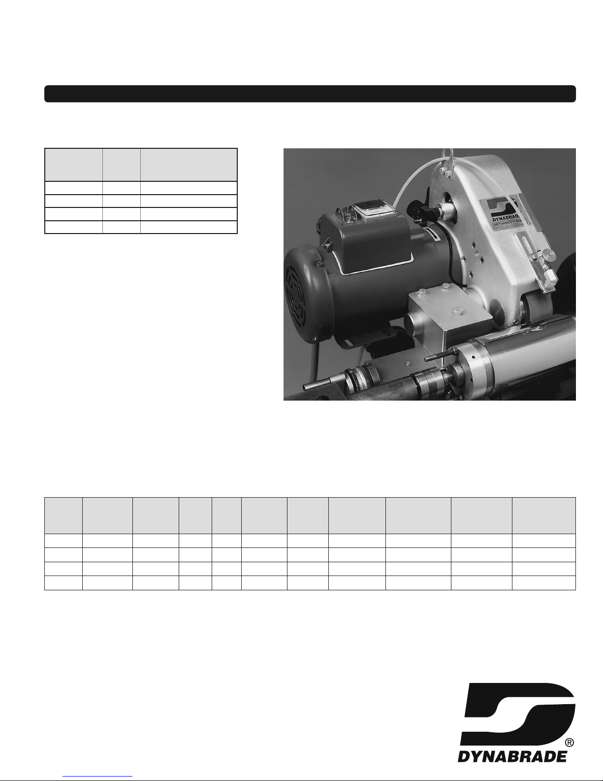
DESCRIPTION
The 2" x 36" Electric Tool Post Grinder is a lathe attachment which uses an abrasive belt driven by
an electric motor to grind and polish cylindrical parts. The abrasive belt is either backed by a contact
wheel at the point of contact with the rotating cylindrical part or the abrasive belt is supported between
two rollers near the point of contact for low pressure grinding and polishing.
INTENDED USE
The 2" x 36" Electric Tool Post Grinder is for industrial use on lathes by trained machinists who have
read and understood this manual. Set-up, maintenance and troubleshooting must be done by trained
industrial technicians who have read and understood this manual.
FORESEEABLE MISUSE
Set up or troubleshooting by unqualified technicians or without consulting this manual.
Use outdoors.
Use while not attached to a lathe.
Use by untrained or unauthorized operators.
Use with flammable liquids for part cooling.
Use in Class 1 or Class 2 hazardous areas
Neglecting maintenance.
Page 4

4
IMPORTANT SAFETY INSTRUCTIONS
READ ALL PARTS OF THIS MANUAL CAREFULLY BEFORE USE
KEEP FOR FUTURE REFERENCE
Definitions
DANGER
Indicates a hazardous situation that, if not avoided, will result in death or serious injury.
WARNING
Indicates a hazardous situation that, if not avoided, could result in death or serious injury.
CAUTION
Indicates a hazardous situation that, if not avoided, could result in minor or moderate injury.
MACHINE SETUP
WARNING Death or serious injury can occur from crushing if the 2" x 36" Electric Tool Post Grinder
tips or falls when lifting from shipping box or pallet. Use lifting hook when removing.
WARNING Death or serious injury can occur from electrocution or arc flash if incorrect connections
are made when connecting electric power. Connections must be made by trained industrial
technicians or electricians only.
WARNING Death or serious injury can occur from fire if the 2" x 36" Electric Tool Post Grinder is
not connected to a rated fuse or circuit breaker. The 2" x 36" Electric Tool Post Grinder
does not come with overcurrent protection and must be connected to a rated fuse or
circuit breaker.
WARNING Death or serious injury can occur from electrocution if the 2" x 36" Electric Tool Post
Grinder is not connected to a rated ground fault protection device. The 2" x 36" Electric
Tool Post Grinder does not come with ground fault protection and must be connected to
a ground fault protection device.
Continued on next page.
Page 5

5
MACHINE SETUP
(CONTINUED)
WARNING Death or serious injury can occur from electrocution or arc flash if electric cord is dam-
aged. Do not pull cord or use cord to move machine.
CAUTION Injury from crushing or cutting is possible if hands or fingers are caught under the 2" x 36"
Electric Tool Post Grinder during installation. Keep hands and fingers clear during installation.
CAUTION Injury from impact is possible from air hose or fitting failure when connecting
compressed air lines.
• Do not exceed 90 PSI.
• Fitting must be prevented from rotating when connecting air line. Use wrench on fittings.
• Connections must be made by trained industrial technicians.
ABRASIVE INSTALLATION
CAUTION On models 64993 and 64991 injury from crushing or cutting is possible if hands or fingers
are caught under belt and pneumatic cylinder actuates unexpectedly when installing abrasive belt. Disconnect compressed air before installing abrasive belt.
CAUTION Injury from crushing or cutting is possible if hands or fingers are caught under belt when
applying tension. Install guards and keep hands and fingers clear during belt tensioning.
CAUTION On models 65014 and 65016 injury from impact is possible if the belt release lever slips
when releasing or applying belt tension. Wear gloves and use a firm grip when operating
the belt release lever.
CAUTION Injury from straining is possible if abrasive belt tension is not released before removing or
installing abrasive belt. Release tension before removing or installing abrasive belt.
Page 6

MACHINE OPERATION
WARNING Death or serious injury can occur from deflagration if operated in a Class 1 or Class 2 haz-
ardous area. The 2" x 36" Electric Tool Post Grinder is not rated for use in Class 1 or Class
2 hazardous areas and could ignite hazardous gas or dust.
WARNING Death or serious injury can occur from deflagration if ferrous and non-ferrous grinding dust
is mixed. Always clean interior and exterior of 2" x 36" Electric Tool Post Grinder between
grinding or polishing ferrous and non-ferrous material.
CAUTION Injury from crushing or cutting is possible if the 2" x 36" Electric Tool Post Grinder is used
without guards in place. Never use without guards.
CAUTION Injury from impact or crushing is possible if adjustments or abrasive belt changes are made
while the lathe is on and the work piece is moving. Always make adjustments and abrasive
changes with the lathe turned off.
CAUTION Injury from crushing or cutting is possible if the 2" x 36" Electric Tool Post Grinder starts
unexpectedly. Always unplug from electric power and compressed air when not in use.
CAUTION Permanent hearing loss is possible if exposure to sound exceeds the limits of Federal,
State or local statutes, ordinances and/or regulations. Wear hearing protection.
CAUTION Eye injury from grinding particles is possible when using abrasive power tools.
Eye protection conforming to ANSI Z87.1 must be worn at all times.
MAINTENANCE
CAUTION Injury from crushing or cutting is possible if the 2" x 36" Electric Tool Post Grinder starts
unexpectedly. Always unplug from electric power and compressed air when performing
maintenance.
CAUTION Injury from slip or fall is possible if floor is wet.
TROUBLESHOOTING
DANGER Death or serious injury will occur from electrocution or arc flash after direct or indirect contact
with live parts. Disconnect electric power before accessing controls.
CAUTION Injury from crushing or cutting is possible if the 2 x 36 Electric Tool Post Grinder starts unex-
pectedly. Always disconnect from electric power and compressed air when troubleshooting.
6
Page 7

7
12 MONTH WARRANTY
Dynabrade warrants all Electric Tool Post Grinders against defects in workmanship and materials
under normal use and service for a period of 12 months from the date of purchase as set forth
herein. Customer must return the defective tool to Dynabrade within 12 months from the date of purchase. Upon examination and review at Dynabrade’s factory, Dynabrade shall confirm whether the
tool qualifies for warranty status, in which case Dynabrade shall repair or replace the tool at no
charge to the customer. Exceptions for in-field examination shall be made only at Dynabrade’s discretion.This warranty is contingent upon proper use of the Electric Tool Post Grinders in accordance
with factory recommendations, instructions and safety practices. It shall not apply to equipment that
has been subjected to misuse, negligence, accident or tampering in any way so as to affect its normal performance. This warranty does NOT cover normally wearable parts and accessories, including, but not limited to electrical switches, cords and plugs, handles and latches, contact wheels and
bearings. This warranty does NOT cover chipped paint or corrosion.To be considered for warranty,
tools must be sent back to our factory, transportation prepaid by customer. Please send tool back
to attention “Repair Department” with note fully explaining the nature of the problem along with a
copy of original invoice indicating model and serial number. Exceptions for in-field repair shall be
made only at Dynabrade’s discretion.This warranty applies only to the original tool owner and is
non-transferable.
THIS WARRANTY IS MADE IN LIEU OF ALL OTHER WARRANTIES, EXPRESS OR IMPLIED,
INCLUDING, BUT NOT LIMITED TO, WARRANTIES OF MERCHANTABILITY OR FITNESS FOR A
PARTICULAR PURPOSE, AND THERE ARE NO OTHER WARRANTIES THAT EXTEND BEYOND
THIS EXPRESS WARRANTY.
Dynabrade will not be liable for damages to products, other property or persons due to improper use
or through attempts to use products for other than their intended use. DYNABRADE WILL NOT BE
LIABLE TO CUSTOMER OR ANY THIRD PARTY FOR ANY SPECIAL, CONTINGENT, INCIDENTAL, INDIRECT OR CONSEQUENTIAL DAMAGES. Dynabrade's liability with respect to a claim for
any other damages arising out of or connected with the manufacture, sale, purchase, non-delivery,
use or performance of any product sold by Dynabrade will in no event exceed to the price paid for
the product.
Page 8

8
SIDE VIEW
“T”- Nut Dimensions
FRONT VIEW
INSTRUCTIONS FOR USE
1/2-13 UNC – 2B
Tapped Hole
Mat’l 303-SS
1-3/4"
1"
3/4"
3/8"
Machine Setup
Step 1 Remove any tooling, tooling holders, etc. from the lathe compound.
Step 2 Clear all chips and debris from the top of compound and “T”-slot.
Step 3 Providing the “T”-nut is of correct size for the lathe compound, lift (or hoist) the entire tool into
position. Align and insert “T”-nut into slot.
Step 4 Using your fingers, lightly snug the Hex Screw (97087) until the tool becomes parallel to the
workpiece centerline.
Step 5 The tool can now be swung from side to side and positioned for the desired angle between the
contact wheel and the workpiece. Once this is achieved, firmly tighten Hex Screw (97087).
Step 6 Position the contact wheel at or above the workpiece centerline. This will ensure proper belt
tracking and prevent chatter from occurring. The position can be altered by loosening the two Cap
Screws (97088) and allowing the tool to pivot on the Pivot Shaft (65266) (tool must be supported
while performing this task!) Firmly retighten the screws once proper positioning is achieved.
Step 7 Connect compressed air (Models 64991 &64993).
Step 8 Connect electric power. See page 11.
The machine is now ready for operation.
4.000
CONTACT WHEEL
2.980
MOUNTING
BLOCK
2.625
1.000
2.500
2.000
CONTACT WHEEL
4.000
MOUNTING
BLOCK
C
L
.530
1.625
5.625
2.000
6.500
Page 9

9
MAINTENANCE
MACHINE OPERATION
Belt Tracking
Belt tracking is accomplished by turning the Tracking Knob (95314). Turning clockwise moves belt to the right.
Tur ning counter-clockwise moves belt to the left.
Coolant Nozzle
The coolant nozzle can be extended or retracted (if dia. allows) for good placement of coolant flow by loosening
Hex Screw (95179). Retighten once placement is achieved. The coolant nozzle has an adjustable flow valve
which connects to 1/4" diameter flexible nylon tubing.
Drip Pan
The drip pan is hinged on a #10 eye screw and can be tilted fore and aft to direct coolant toward lathe bed or
to a drain hose. A 1/4 NPT port is provided at each end for this purpose.
Catch Tray Assembly
Each machine comes equipped with an adjustable catch tray which positions underneath the contact wheel.
Its purpose is to collect the major portion of grind dust/swarf and direct it away from the lathe ways. It should
be placed within 1/8" of workpiece. Position can be changed by loosening Knob (97773). When grinding into
a shoulder, it will be necessary to remove tray entirely.
The grinders described in this manual have been designed to be maintenance-free. All bearings and moving
parts are sealed and lubricated for life. Electric motor maintenance should be performed as recommended by
the motor manufacturer.
Good housekeeping is essential to insuring long life of any machine tool. By keeping the machine clean and
visually inspected for any wear, the machine will provide many years of quality service.
Periodically inspect the contact wheels, idler rolls and drive pulley for any signs of wear. Repairing or replacing
worn parts early enough will prevent other parts from becoming damaged.
Belt Installation/Change
Step 1 Remove Belt Guard by grasping Door Latch (97760)
and rotate quarter turn counter-clockwise.
Step 2 Pull the belt release lever rearward until distinctive
“click” or catch is felt indicating the engagement of
cam mechanism into machined groove.
Step 3 Important: With firm rearward hold on release lever
handle, remove belt with left hand.
Step 4 Install new belt in same manner.
Step 5 With hand and fingers free from moving parts, push
release lever forward until belt becomes taught.
Replace belt guard and turn door latch quarter turn clockwise until “click” is heard.
Page 10

10
FEATURES
Handy belt-release
lever allows quick
belt changes
Easily accessible
belt-tracking adjustment.
Water-tight
on/off switch.
70 durometer fixed
contact wheel is
standard.
Coolant drip-pan deflects
stray coolant.
Rigidly mounts
to lathe compound
for close tolerance
work.
Page 11

11
ELECTRICAL SCHEMATICS
65014 & 64991
DPST
230 V
1 Phase
60 Hz
M
A
OPT.
65016 & 64993
DPST
230 V
1 Phase
50 Hz
M
A
OPT.
Nema Configuration Locking Type Plug
Plug not included
L6 – 2OP
X
V
G
Page 12

12
Item Part No. Description Qty.
1 65271 Housing 1
2
65335 Electric Assembly (50 Hz) 1
65349 Electric Assembly (60 Hz) 1
3 98377 Ammeter 1
4 98369 Switch 1
5 98370 Switch Guard 1
6 65195 Mounting Block 1
7 98493 T-Nut 1
8 65266 Pivot Bar 1
9 14333 Lift Bracket 1
10 66616 Tension Block 1
11 95696 Guage 1
12
65238 Drive Wheel (64991) 1
65306 Drive Wheel (64993) 1
13 65233 Contact Wheel Shaft 1
14 97026 Screw 1
15 97502 Ball Bearings 2
16 97436 Retaining Ring 1
17 65263 Tray (includes rod) 1
18 97773 Knob 1
19 65314 Tray Support 1
20 97061 Screw 2
21 65268 Vacuum Cover 1
22 97760 Door Latch 1
23 97053 Screw 3
24 95179 Hex Screw 2
25 95167 Lock Washer 2
26 97088 Hex Screw 2
27 95183 Flat Washer 2
28 97057 Cap Screw 4
29 97059 Cap Screw 3
30 97087 Hex Screw 1
31 97310 Flat Washer 1
32 97085 Flathead Screw 4
33 97460 Key 1
34 97069 Carriage Bolt 2
35 97806 Air Cylinder 2
36 97112 Set Screw 1
37 97828 Fitting 2
38 97829 Hose 1
39 97083 Flathead Screw 4
40 65232 Tension Strap 1
41 97883 Breather Vent 1
42 97894-B Valve 1
43 97898-C Regulator 1
44 97812 Oil Seal 4
45 65217 Bushing 4
46 65338 Contact Wheel 1
47 65267 Tension Shaft 2
48 97479
Spring 2
49 97731 Shoulder Washer 4
50 97058 Cap Screw 4
51 65269 Tension Support 1
52 95202 Set Screw 1
53 97556 Bushing 2
54 97405 Roll Pin 2
55 65075 Idler Support 2
56
65236 Tracking Wheel (64991) 1
65307 Tracking Wheel (64993) 1
57 97518 Ball Bearing 2
58 97441 Retaining Ring 2
59 65130 Tracking Shaft 1
60 65132 Tracking Hub 1
61 97152 Low Head Screw 4
62 95417 Nylon Washer 2
63 95186 Hex Nut 1
64 95314 Knob 1
65 65264 Drip Pan 1
66 95166 Flat Washer 1
67 95167 Lock Washer 1
68 95170 Wing Nut 1
69 97151 Eye Screw 1
70 65262 Nozzle Support 1
71 95761 Va lve 1
72 95084 Reducer 1
73 96063 Elbow 1
64991
3,450 RPM, 60Hz
64993
2,850 RPM, 50Hz
17
19
20
18
3
33
24
25
4
2
26
30
31
6
7
8
28
24
24
65
66
66 67 68 69
71
70
72
73
36
1
23
32
9
27
5
Page 13

13
13
44
45
40
39
38
16
39
50
15
14
12
52
61
60
63
59
53
54
58
56
57
55
54
53
21
22
51
47
44
45
10
62
64
11
29
14
42
43
41
37
38
23
23
34
37
35
Page 14

14
Item Part No. Description Qty.
1 65271 Housing 1
2
65335 Electric Assembly (50 Hz) 1
65349 Electric Assembly (60 Hz) 1
3 98377 Ammeter 1
4 98369 Switch 1
5 98370 Switch Guard 1
6 65195 Mounting Block 1
7 98493 T-Nut 1
8 65266 Pivot Bar 1
9 14333 Lift Bracket 1
10 11535 Handle 1
11 65219 Release Lever 1
12
65238 Drive Wheel (65014) 1
65306 Drive Wheel (65016) 1
13 65233 Contact Wheel Shaft 1
14 65237 Contact Wheel 1
15 97502 Ball Bearings 2
16 97436 Retaining Ring 1
17 65263 Tray (includes rod) 1
18 97773 Knob 1
19 65314 Tray Support 1
20 97061 Screw 2
21 65268 Vacuum Cover 1
22 97760 Door Latch 1
23 97530 Flanged Bushing 3
24 95179 Hex Screw 2
25 95167 Lock Washer 2
26 97088 Hex Screw 2
27 95183 Flat Washer 2
28 97057 Cap Screw 4
29 97059 Cap Screw 3
30 97087 Hex Screw 1
31 97310 Flat Washer 1
32 97085 Flathead Screw 4
33 97460 Key 1
34 97011 Cap Screw 2
35 95359 Flat Washer 2
36 97112 Set Screw 1
37 65265 Release Lever Shaft 1
38 97110 Set Screw 2
39 97083 Flathead Screw 4
40 65232 Tension Strap 1
41 65234 Release Cam 1
42 11016 Ball Bearing 1
43 97406 Roll Pin 1
44 97812 Oil Seal 4
45 65217 Bushing 4
46 65235 Tension Block 1
47 65267 Tension Shaft 2
48 97479
Spring 2
49 97731 Shoulder Washer 4
50 97058 Cap Screw 4
51 65269 Tension Support 1
52 95202 Set Screw 1
53 97556 Bushing 2
54 97405 Roll Pin 2
55 65075 Idler Support 2
56
65236 Tracking Wheel (65014) 1
65307 Tracking Wheel (65016) 1
57 97518 Ball Bearing 2
58 97441 Retaining Ring 2
59 65130 Tracking Shaft 1
60 65132 Tracking Hub 1
61 97152 Low Head Screw 4
62 95417 Nylon Washer 2
63 95186 Hex Nut 1
64 95314 Knob 1
65 65264 Drip Pan 1
66 95166 Flat Washer 1
67 95167 Lock Washer 1
68 95170 Wing Nut 1
69 97151 Eye Screw 1
70 65262 Nozzle Support 1
71 95761 Valve 1
72 95084 Reducer 1
73 96063 Elbow 1
17
19
20
18
3
33
24
25
4
2
26
30
31
6
7
8
28
24
24
65
66
66 67 68 69
71
70
72
73
36
11
23
32
34
27
10
5
65014
3,450 RPM, 60Hz
65016
2,850 RPM, 50Hz
Page 15

15
13
37 44
45
35
34
40
39
38
16
39
50
15
14
12
52
61
60
63
59
53
54
58
56
57
55
54
53
21
22
51
47
48
49
44
45
46
23
41
42
43
62
64
1
9
29
Page 16

DYNABRADE, INC. www.dynabrade.com
8989 Sheridan Drive •Clarence, NY 14031-1419 •Phone: 716-631-0100 •Fax: 716-631-2073 •International Fax: 716-631-2524
© DYNABRADE, INC., 2014 PD14.10_04/14
OPTIONAL ACCESSORIES
Superfinishing requires very clean coolant. If the coolant is not filtered, the grinding residue will act as
an abrasive slurry, which can affect the final finish. Dynabrade’s 68000 Coolant Filtration System filters
the coolant to 1µ, eliminating this problem.
Model 68000
115 Volt, 1 Phase
Model 68100
230 Volt, 1 Phase
Model 68101
230 Volt, 3 Phase
• 120 Volt System for easy hookup.
• 2-stage filters to prevent 1-micron filter
from clogging prematurely.
• 40 gallon tank – removable for cleaning.
• Transparent Tank for viewing coolant level.
• Easy access for changing filters.
• Self-priming Centrifugal Pump.
• GFI protection.
Replacement Filters
Part No. 66631
• 1-micron Disposable Filter Cartridge.
Part No. 66635
• 5-micron Disposable Filter Cartridge.
COOLANT FILTRATION SYSTEM
CONTACT WHEELS
Part
Number
Diameter
Inch (mm)
Width
Inch (mm)
Face
Material
65237 4 (102) 2 (51) 70 Duro Rubber
65338* 4 (102) 2 (51) 90 Duro Rubber
65339 4 (102) 2 (51) 50 Duro Rubber
65340 4 (102) 2 (51) Steel
Part No. 65415
• 2" (51 mm) x 36" (915 mm).
• Specialized contact arm assembly
allows slack polishing of workpieces
up to 20" (508 mm) diameter.
*Standard on machine. All include 2 each of 97502 Bearing.
SLACK BELT ATTACHMENT
DYNACUT ABRASIVE BELTS
DynaCut Aluminum Oxide (A/O) Coated Abrasive Belts
The most common mineral for general purpose applications, primarily on softer metals.
For light and heavier grinding, plus blending on aluminum, carbon steel, brass and bronze.
•
Call for availability and pricing.
W x L
(Inches)
Belt
Type
Belt Brand
36
Grit
40
Grit
60
Grit
80
Grit
120
Grit
180
Grit
220
Grit
320
Grit
Package
Quantity
2 x 36 A/O DynaCut
• •
91637 91638 91639 91640 91641 91642 10
 Loading...