

Page 1
Reorder No. PD05.20
Supersedes PD04.21
IMPORTANT SAFETY INSTRUCTIONS
1. Components used in packaging (ie. plastic bags) can be
dangerous keep away from children and animals.
2. The unit is for DRY USE ONLY and must be stored in a dry room.
3. The use of this machine for anything not specified in this
manual may be dangerous and must be avoided.
4. The suction nozzle should be kept away from the body,
especially delicate areas such as the eyes, ears and mouth.
5. The equipment should be correctly assembled before use.
6. Ensure that power socket is correct for the machine.
7. Check the voltage indicated on the rating plate is the same as
the supply voltage.
8. These machines are not designed for picking up health
endangering dusts or inflammable/explosive substances.
9. Never leave the equipment unattended while in use.
10. Never use this equipment to pick up any kind of liquid.
11. Never carry out any maintenance on the machine without first
disconnecting from the main supply, if the machine is to be left
unattended the supply should also be terminated.
12. The main supply cable should not be used to pull or lift the
machine.
13. The machine should never be emersed in water or a pressure
jet of water used for cleaning.
14. Periodically examine the main cable and machine for damage.
If any damage is found contact your service centre for repair.
15. Should extension cables be used, ensure that the cable rating
is suitable for use with the equipment. Do not use the cable
coiled as this could result in a voltage drop or overheating.
Keep dry at all times.
16. This equipment should NOT be used to pick up water from
containers, lavatories, tubs, etc.
17. Service and repairs must be carried out by qualified personnel
only. Replacement parts for the machine must be
manufacturers original spare parts only.
18. The manufacturer cannot be held responsible for any
damage/injury caused to persons or property, because of the
incorrect use of the machine due to procedures being used
which are not specified in this instruction manual.
These Portable Vacuum Systems have been developed as a
safe, portable, mobile, yet powerful industrial tool for
commercial use. To ensure that this quality equipment is
properly used and maintained to its full capability, please
carefully read the following safety instructions and operating
procedures before commencement of the operation.
When operating this equipment, basic precautions should always be strictly followed
including the instructions listed below:
“M” CLASS DRY VACUUM
When employed in accordance with their intended use, the industrial vacuum
cleaners described in these operating instructions are suitable for picking up
non-flammable, dry dusts. They correspond to dust class “M” in accordance to:
EN 60335-2-69. By SLG, Germany
61300 (9.9 gal./36 ltr.) 120v-60Hz (US)
61301 (17 gal./64 ltr.) 120v-60Hz (US)
61302 (9.9 gal./36 ltr.) 230v-50Hz (UK)
61303 (17 gal./64 ltr.) 230v-50Hz (UK)
61304 (9.9 gal./36 ltr.) 110v-60Hz (UK)
61305 (17 gal./64 ltr.) 110v-60Hz (UK)
61306 (9.9 gal./36 ltr.) 230v-50Hz (EUR)
61307 (17 gal./64 ltr.) 230v-50Hz (EUR)
61308 (9.9 gal./36 ltr.) 230v-50Hz (OUS)
61309 (17 gal./64 ltr.) 230v-50Hz (OUS)
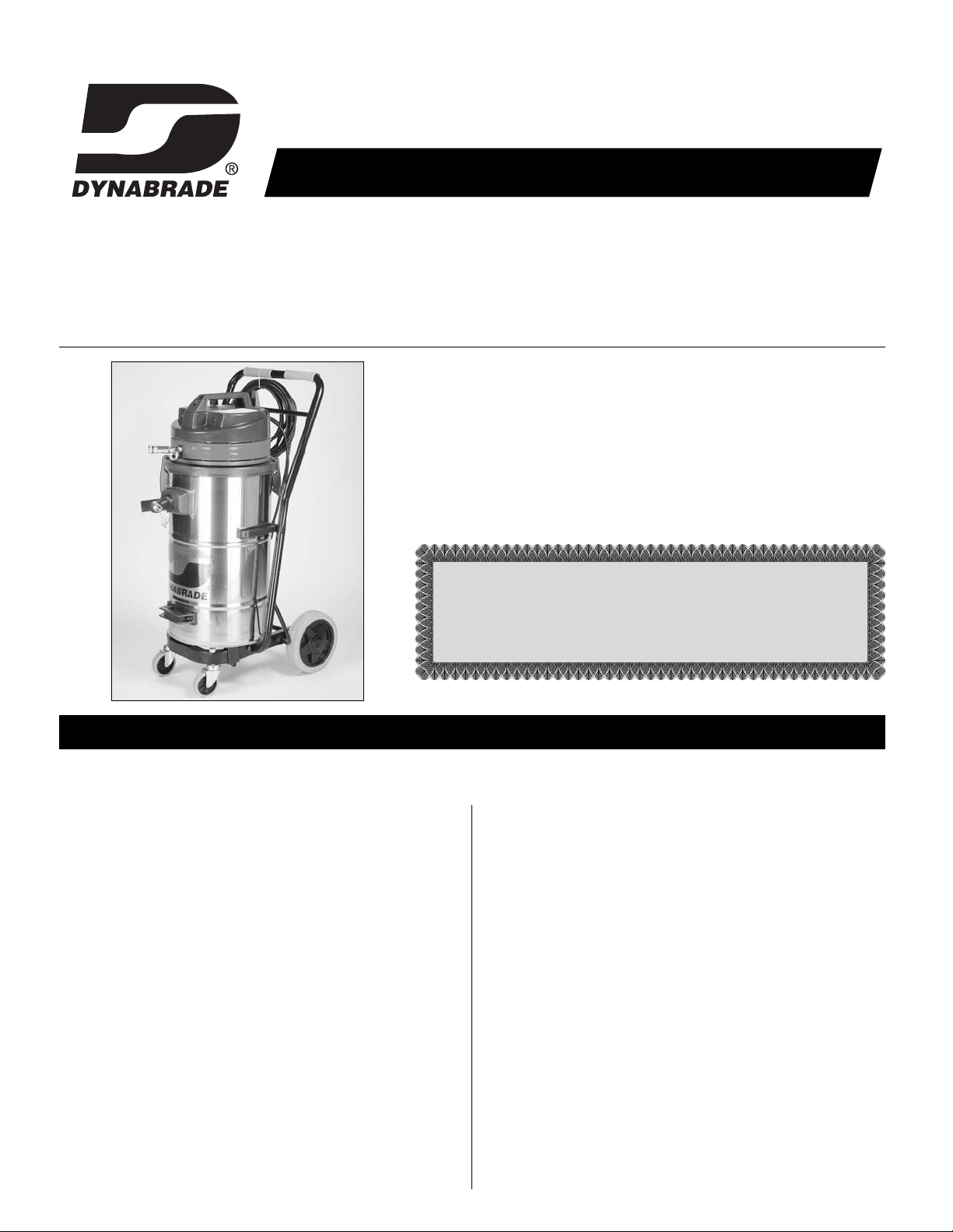
Portable Vacuum System
Operating Manual
Page 2

ASSEMBLY INSTRUCTIONS
1. While opening the carton, carefully inspect outside of the
carton for any sign of transportation damage, and if so, notify
your shipper immediately.
2. Open carton and remove hoses, hose connectors and other
accessories.
3. Lay carton on its back and wheel the unit out.
4. Remove all packing, release the unit and remove
Motorhead/Vacuum Head Assembly to make sure no packing
materials are left inside the unit.
5. Check to make sure the filter is seated firmly. If not, tighten at
base of filter unit.
7. Remove the vacuum hose assembly. Note that the air supply
tube (the smaller of the two) protrudes at both ends and is
longer than the vacuum hose.
8. Connect quick coupler male end to air outlets located on
vacuum head assembly.
9. Insert vacuum hoses.
10. Connect air supply to air inlet fitting (1/4" NPT female threads)
located at the back side of Motorhead. Air pressure should be
adjusted according to the pressure requirement of the air tools
you are using. Do not exceed 150 PSIG (10.3 kg/cm2). Some
pressure drop is unavoidable between the main air supply and
the air tools due to internal flow resistance in a long air hose.
Air pressure of 20 to 30 PSIG (1.4 to 2.0 kg/cm2) higher
than the air pressure specified for the air tool being used
is recommended.
The installation of a Dynabrade Filter-Regulator-Lubricator
(FRL Part No. 11411) is highly recommended to protect the
unit and the air tools.
Where it is critical to avoid shocks or sparks caused by
static electricity, an air supply hose which is electrically
conductive and ground must be used.
11. All Dynabrade Vacuum Models come with a sample dust bag.
Install bag inside main body. Make sure that vacuum
connection tube protrudes through the hole in the bag.
12. Order dust bags (Part No. 64682) before you run out of them.
13. Return Motorhead/Vacuum Head Assembly to the unit and lock
the two rim clamps to secure Motorhead/Vacuum Head
Assembly in position.
14. Connect your Dynabrade air tool or accessory and you are now
ready for working with the Dynabrade Portable Vacuum System.
CAUTION
THIS IS A PRECISION PIECE OF EQUIPMENT designed for dust extraction to keep your ENVIRONMENT
and your REPUTATION “DUST-FREE.” Read operating instructions before using Dynabrade Portable
Vacuum System and be thoroughly conversant with safety precautions in your locality.
Refer to the drawing and parts list for the name and location of parts.
OPERATING INSTRUCTIONS
1. Always wear safety glasses and any other safety items
required by law.
2. The vacuum system will operate by an on/auto/manual switch
located on the front of the Motorhead/Vacuum Head Assembly.
This switch must be turned on to activate the Motorhead.
3. VACUUM SPEED CONTROL: Unit is equipped with a rheostat
motor control. Infinitely adjustable speed allows suction
regulation for wide range of tools.
4. ELECTRONIC THERMAL PROTECTION DEVICE: Unit is
equipped with a overload prevention system. If this feature is
activated a 20 MIN. COOL DOWN PERIOD inhibits use. After a
complete 20 min. cool down period has passed the Electronic
Thermal Protection Device will RE-SET automatically and
the unit will be on line ready for use.
5. VISUAL WARNING SIGNAL: Unit is equipped with a visual
warning (yellow) light to indicate when air velocity falls below
20m/s. Turn off vacuum and replace disposable collection bag.
The warning signal will RE-SET automatically and the unit will
be ready for use.
The following items should be well-noted for the effective use of the unit.
GROUNDING INSTRUCTIONS
This unit must be grounded. If it should malfunction or breakdown,
grounding provides a path of least resistance for electric current to
reduce the risk of electric shock.
Where it is critical to avoid shocks or sparks caused by static
electricity, an electrically conductive and grounded air supply
hose must be used.
PAGE 2
WARNING
Grounding by means of a ground wire between both ends of the air supply tubing
passing through vacuum hose is recommended.
NEW!
NEW!
Page 3

PAGE 3
OPERATING TIPS AND TROUBLESHOOTING
Keep machine clean to ensure optimum performance. After each
use, lift off vacuum head and knock dust from filter. After one hour
of continuous use, lift out the Motorhead/Vacuum Head Assembly
and check the amount of dust accumulated in the unit. Remove the
dust bag if necessary and replace with a new one. We recommend
a soft brush to clean the filter. DO NOT USE A BLOW GUN.
Decrease in Vacuum Performance
1. Clean the filter thoroughly and as often as necessary. The
filter used inside is water resistant and washable. To prevent
damage, do not use high pressure or solvent to wash the filter.
2. If the filter (P/N 64684) should become damaged or badly
clogged and cannot be cleaned, replace with a new one.
3. Check all the vacuum lines for blockage or leakage.
Vacuum Stops During Use
1. This vacuum is equipped with a Electronic Thermal Protection
Device. If the vacuum stops and the red indicator light appears
ON, the unit has shut down as a result of increased
temperature. Once the unit has regained a temperature that is
allowable for operation the vacuum will resume operation.
REMOVAL/INSTALLATION OF MOTORHEAD FROM MAIN ASSEMBLY
If the filter element becomes clogged or to clean the inner portions
of the drum (canister) the Motorhead Assembly must then be
removed to perform cleaning. When removal becomes necessary for
cleaning or other service, follow the procedures described below.
Removal
1. Unplug the unit before attempting service or maintenance
work.
2. Remove Top Lid by unlatching (2) hinges.
3. Use a conventional vacuum cleaner to clean entire inside of
Motorhead/Vacuum Head Assembly and drum (canister).
Upon completion of the service work, install top lid according to
the following procedure:
Installation
1. Place cleaned unit onto the drum (canister) and latch (2)
hinges to properly attach the lid. Unit is now ready for
operation.
TILT-N-CLEAN OPERATION INSTRUCTION
94941 COAXIAL VACUUM HOSE ASSEMBLY
Unit has a Tilt-n-Clean feature to aid in overall functionality of the
work equipment and work environment:
1. Unplug the unit before attempting service or maintenance
work.
2. Unclamp and remove Motorhead/Vacuum Head Assembly.
Drum (canister) is now able to be tilted backwards and
emptied. Dispose of debris properly.
3. Or, Pull side release hinges away from the drum (canister)
and remove the entire drum (canister) from the trolley. With
drum (canister) removed dispose of debris properly.
Cuff
Swivel Adapter
P/N 96573
Cuff1-1/4" Vac Hose Cuff with Air Line Exit
Cuff with Air
Line Exit
1-1/4" Vac Hose1-1/4" Vac Hose
Insert
P/N 95895
For Older Two-Hand Tools
Air Line Assembly - 28 cm of Air Line
Assembly will Extend Past the Cuff
Dynabrade Male Plug
P/N 95675
Dynabrade Female Plug
P/N 95677
35 cm of Air
Line Assembly
will Extend Past
the Cuff
Dynabrade Coupler
P/N 94960
Page 4

MACHINE PARTS LIST – (9.9 gal./36 ltr.)
ITEM PART NO. DESCRIPTION
1 64684 H.E.P.A. Filter
64683 (Optional) Paper Cartridge Filter
2 64685 Felt Insert
3 64682 Disposable Vacuum Bag (10/Pkg.)
4 80055 Tipping Handle Assembly
5 80052 Rear Wheel Assembly
6 80050 Standard Front Wheel Assembly
7 80059 Motor (110/120 V - 60 Hz)
80060 Motor (230 V - 50 Hz)
8 80077 Power Switch
9 80053 Vacuum Speed Control Assembly (110/120 V - 60 Hz)
80054 Vacuum Speed Control Assembly (230 V - 50 Hz)
1
2
4
6
5
3
Motorhead Assembly
7
8
9
Replacement Brushes:
80057 110/120 V - 60 Hz. (Qty. 2)
80058 230 V - 50 Hz. (Qty. 2)
Page 5

MACHINE PARTS LIST – (17 gal./64 ltr.)
1
2
3
4
6
5
7
MOTORHEAD ASSEMBLY
8
9
ITEM PART NO. DESCRIPTION
1 64684 H.E.P.A. Filter
64683 (Optional) Paper Cartridge Filter
2 64687 Felt Insert
3 80076 Disposable Vacuum Bag (10/Pkg.)
4 80056 Tipping Handle Assembly
5 80052 Rear Wheel Assembly
6 80050 Standard Front Wheel Assembly
7 80059 Motor (110/120 V - 60 Hz)
80060 Motor (230 V - 50 Hz)
8 80077 Power Switch
9 80053 Vacuum Speed Control Assembly (110/120 V - 60 Hz)
80054 Vacuum Speed Control Assembly (230 V - 50 Hz)
Replacement Brushes:
80057 110/120 V - 60 Hz. (Qty. 2)
80058 230 V - 50 Hz. (Qty. 2)
Page 6

TECHNICAL SPECIFICATIONS – PORTABLE VACUUM SYSTEMS
Model No.............................All Models (Reference Pg. 1)
Noise Level ........................ 76 Decibels
Air Pressure........................ 80 to 150 PSIG (5.6 to 10.4 kg/cm
2
)
Filter.................................... H.E.P.A. (0.3 micron)
Unit Capacity Size .............. 9.9 gallon/36 liter
17 gallon/64 liter
No. of Vacuum Outlets ...... 2
No. of Pneumatic Outlets .. 2
Construction ...................... Stainless Steel Drum (Canister)
Remainder: Plastic and Metal Components.
Dust & Debris Collection.... Paper Bag, H.E.P.A.(0.3 micron) w/ felt insert.
Standard Accessories ........ 2 Pieces of 1-1/4" I.D. x 20' Long Flexible Vacuum
Hose with Built-In 3/8" I.D. Air Supply Tubing
Standard Vacuum Hose .... (2) 20' x 1-1/4" Light Weight Coaxial Hose
(6M x 32mm)
Vacuum Control.................. Variable
Cord Set .............................. 27' (8M)
OPTIONAL ACCESSORIES
DYNABRADE CUSTOMER SERVICE
US Consumers Call Toll-Free: 1-800-828-7333 •Canadian Consumers Call Toll-Free: 1-800-344-1488
www.dynabrade.com
© DYNABRADE, INC., 2005 PRINTED IN USA PD05.20_05/04
Replacement Brushes
80057 110 V - 60 Hz. (Qty. 2)
80058 230 V - 50 Hz. (Qty. 2)
Disposable Vacuum Paper Bag
• A minimum order quantity of 10.
64682 (9.9 gal./36 ltr.) 10/Pkg.
80076 (17 gal./64 ltr.) 10/Pkg.
Vacuum Tray
• A convenient storage shelf to place
work related items.
96567 (9.9 gal./36 ltr.)
96563 (17 gal./64 ltr.)
96581 Vacuum Tray Hose Hanger
• Easily installed onto Vacuum Tray.
(Requires Vacuum Tray To Install.)
96558 Vacuum Cleaning Kit
(Includes The Following)
- Hose - Curved Handle
- Extension Pipe (2)
(Includes The Following Attachments)
- Round Brush - Coarse Dirt Nozzle
- Crevis Tool
80051 Locking Front Wheel Assembly
• Allows to lock the entire unit with the
simple ease of a push-lock system.
64686 “Y” Vacuum Connector
• Allows for two tools to be connected to
the same Portable Vacuum System.
Dynabrade Offers A Complete
Line of Hose Cuffs and
Reducers. Refer To
Dynabrade's Current Catalog
(Russian GOST)
0406
14HA
“M” CLASS DRY VACUUM
DYNABRADE, INC.
8989 Sheridan Drive • Clarence, New York 14031-1490 • Phone: (716) 631-0100
Fax: 716-631-2073 •
US Consumers Call Toll Free: 1-800-828-7333
DYNABRADE INTERNATIONAL
8989 Sheridan Drive • Clarence, New York 14031-1490 • Phone: (716) 631-0100
Fax: 716-631-2524 •
Canadian Consumers Call Toll Free: 1-800-344-1488
DYNABRADE EUROPE S.à r.l.
Zone Artisanale • L-5485 Wormeldange-Haut, Luxembourg
Phone: +352 768 494 1 • Fax: +352 768 495
DYNABRADE DO BRASIL
Rua Mário Fongaro • 421 – Vila Marlene • São Bernardo do Campo
SP – CEP 09732-530 • Telefax: (11) 4124-6040
 Loading...