

Dynabrade 59001, 59000, 59004, 59003, 59002 Safety, Operation And Maintenance
...
SAFETY INSTRUCTIONS
Carefully Read all instructions before operating or servicing any Dynabrade®Abrasive Power Tool.
Products offered by Dynabrade are not to be modified, converted or otherwise alerted from the original design without expressed written consent from Dynabrade, Inc.
Tool Intent: Dynorbital-Spirit™ Random Orbital Sander is used for sanding and finishing a variety of materials including wood, metal, plastic, fiberglass, solid surfaces,
composites, rubber, glass and stone.
Do Not Use Tool For Anything Other Than Its Intended Applications.
Training: Proper care, maintenance, and storage of your tool will maximize its performance.
• Employer's Responsibility – Provide Dynorbital- Spirit™ operators with safety instructions and training for safe use of tools and accessories.
Accessory Selection:
• Abrasive/accessory RPM (speed) rating MUST be approved for AT LEAST the tool RPM rating.
• Before mounting an accessory, visually inspect for defects. Do not use defective accessories.
• Follow tool specifications before choosing size and type of accessory.
• Only use recommended fittings and air line sizes. Air supply hoses and air hose assemblies must have a minimum working pressure rating of 150 PSIG (10 bars, g) or 150
percent of the maximum pressure produced in the system, whichever is higher. (See Tool Machine Specifications Table.)
• DO NOT use – ......................................................
OPERATING INSTRUCTIONS
Warning: Always wear eye protection. Operator of tool is responsible for following: accepted eye, face, respiratory, hearing and body protection.
Caution: Hand, wrist and arm injury may result from repetitive work, motion and overexposure to vibration.
(Continued on next page.)
Parts Page Reorder No. PD02•10U
Effective February, 2002
Dynorbital-Spirit
™
Air Tool Manual – Safety, Operation and Maintenance
Models:
3/8" Orbit 3/16" Orbit 3/32" Orbit
59000 59010 59015 59025 59030 59040
59001 59011 59016 59026 59031 59041
59002 59012 59017 59027 59032 59042
59003 59013 59018 59028 59033 59043
59004 59014 59019 59029 59034 59044
59005 59100 59020 59105 59035 59110
59006 59101 59021 59106 59036 59111
59007 59102 59022 59107 59037 59112
59008 59103 59023 59108 59038 59113
59009 59104 59024 59109 59039 59114
FOR COMPLETE MODEL DESCRIPTION REFERENCE PAGE 6.
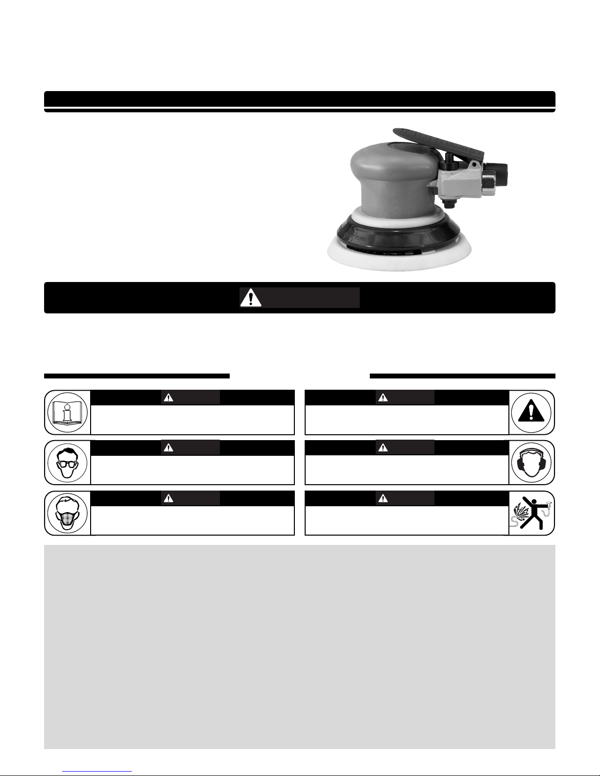
SAFETY LEGEND
G
Read and understand tool manual before
work starts to reduce risk of injury to
operator, visitors, and tool.
Eye protection must be worn at all times,
eye protection to conform to ANSI Z87.1.
Respiratory protection to be used when exposed to
contaminants that exceed the applicable threshold
limit values required by law.
Practice safety requirements. Work alert,
have proper attire, and do not operate tools under
the influence of alcohol or drugs.
Ear protection to be worn when exposure to sound,
exceeds the limits of applicable Federal, State or
local statues, ordinances and/or regulations.
Air line hazard, pressurized supply lines and flexible
hoses can cause serious injury. Do not use dam-
aged, frayed or deteriorated air hoses and fittings.
Read and understand this tool manual before operating your air tool. Follow all safety rules for the protection of operating personnel as well as adjacent areas. Always operate, inspect and maintain this tool in accordance with the American National Safety
Institute (ANSI) Safety Code for Portable Air Tools – B186.1. For additional safety information, refer to Safety Requirements for the
Use, Care and Protection of Abrasive Wheels – ANSI B7.1, Code of Federal Regulation – CFR 29 Part 1910, European Committee for
Standards (EN) Hand Held Non-Electric Power Tools – Safety Requirements and applicable State and Local Regulations.
SAVE THIS DOCUMENT, EDUCATE ALL PERSONNEL
12,000 RPM Air Powered Random Orbital Sander
WARNIN
WARNING
WARNING
WARNING
WARNING
WARNING
WARNING
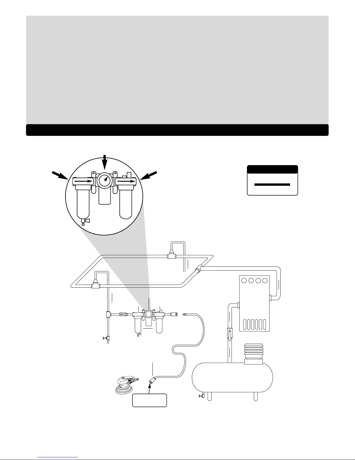
To Tool Station
Closed Loop Pipe System
(Sloped in the direction of air flow)
Ball
Valve
Ball
Valve
Filter
Coupler
Regulator
Lubricator
Air Flow
Drain
Valve
Drain
Valve
Air Tool
Air Compressor
and Receiver
Drain Valve
Air Hose
90 PSIG MAX
(6.2 Bar)
Air Flow
Refrigerated
Air Dryer
2
Filter
Regulator
Lubricator
90 PSIG
(6.2 Bar)
OPERATING INSTRUCTIONS (continued)
• Keep hand and clothing away from working end of the air tool.
Operation: Be sure that any loose clothing, hair and all jewelry is properly restrained.
• Secure inlet bushing on air tool with a wrench before attempting to install the air fitting to avoid damaging housing assembly.
• Check tool RPM (speed) with tachometer with air pressure set at 90 PSIG while the tool is running. If tool is operating at a higher speed than the RPM marked on the tool
housing, or operating improperly, the tool must be serviced and corrected before use.
Caution: Tool RPM must never exceed abrasive/accessory RPM rating. Check accessory manufacturer for details on maximum operating speed or special
mounting instructions.
• With power source disconnected from air tool, mount recommended accessory into collet assembly.
• Connect air tool to power source. Be careful NOT to depress throttle lever in the process. Do not expose air tool to inlet pressure above 90 PSIG or (6.2 Bars).
Caution: After installing the accessory, before testing or use and/or after assembling tool, the Dynorbital-Spirit™ must be started at a reduced speed to check for good
balance. Gradually increase tool speed. DO NOT USE if tool vibration is excessive. Correct cause, and retest to insure safe operation.
• Make sure that work area is uncluttered, and visitors are at a safe range from the tools and debris.
• Use a vise or clamping device to hold work piece firmly in place.
• Do not apply excessive force on tool or apply “rough” treatment to it.
• Always work with a firm footing, posture and proper lighting.
Report to your supervisor any condition of the tool, accessories, or operation you consider unsafe.
Air System
1 DROP/MIN.
10 SCFM
LUBRICATOR SETTING
• Ideally the air supply should be free from moisture.
Incorporating a refrigerated air dryer after the
compressor and drain valves at each tool station
(as shown) further reduces moisture from
condensation in the air supply.
• Dynabrade Air Power Tools are designed to
operate at 90 PSIG (6.2 Bar/620 kPa) maximum
air pressure at the tool inlet, when the tool is
running. Use recommended regulator to control
air pressure.
➤
➤
➤
➤
➤
➤

Maintenance Instructions
Important: A Preventative Maintenance Program is recommended whenever portable power tools are used.
• Use only genuine Dynabrade replacement parts to insure quality. To order replacement parts, specify Model#, Serial# and RPM of your air tool.
• All Dynabrade Rotary Vane air tools must be used with a Filter-Regulator-Lubricator to maintain all warranties. Dynabrade recommends the following:
11405 Air Filter-Regulator-Lubricator (FRL) – Provides accurate air pressure regulation and two stage filtration of water contaminants. Operates 40
SCFM/1,133 LPM @ 100 PSIG with 3/8" NPT female ports.
• Dynabrade recommends one drop of air lube per minute for each 10 SCFM (example: if the tool specification states 40 SCFM, set the drip rate on the
filter-lubricator to 4 drops per minute). Dynabrade Air Lube (P/N 95842: 1 pt 473 ml) is recommended.
Routine Preventative Maintenance: Check free speed of Dynorbital-Spirit™ using a tachometer.
• Mineral spirits are recommended when cleaning the tool and parts. Do not clean tool or parts with any solvents or oils containing acids, esters,
ketones, chlorinated hydrocarbons or nitro carbons.
• DO NOT
clean or maintain tools with chemicals that have a low flash point (example: WD-40®).
• A Drop-In Motor and Tune-Up Kit are available, see specific kit number on page 8.
• Air tool stampings must be kept legible at all times, if not, reorder and replace. User is responsible for maintaining specification information i.e.:
Model #, S/N, and RPM.
• Blow air supply hose out prior to initial use.
• Visually inspect air hoses and fittings for frays, visible damage and signs of deterioration. Replace damaged or worn components.
• Refer to Dynabrade's Warning/Safety Operating Instructions Tag (Reorder No. 95903) for safety information.
After maintenance is performed on tool, add a few drops of Dynabrade Air Lube (P/N 95842) to the air line and start the tool a few times to lubricate air motor.
Check for excessive tool vibration.
Handling and Storage:
• Protect tool inlet from debris (See Notice Below).
• DO
NOT carry tool by air hose.
• Protect abrasive accessories from exposure to water, solvents, high humidity, freezing temperature and extreme temperature changes.
• Store accessories in protective racks or compartments to prevent damage.
Notice
All Dynabrade motors use the highest quality parts and materials available and are machined to exacting tolerances. The failure of quality pneumatic motors
can most often be traced to an unclean air supply or the lack of lubrication. Air pressure easily forces dirt or water contained in the air supply into motor
bearings causing early failure. It often scores the cylinder walls and the rotor blades resulting in limited efficiency and power. Our warranty obligation is
contingent upon proper use of our tools and cannot apply to equipment which has been subjected to misuse such as unclean air, wet air or a lack of
lubrication during the use of this tool.
One Year Warranty
Following the reasonable assumption that any inherent defect which might
prevail in a product will become apparent to the user within one year from
the date of purchase, all equipment of our manufacture is warranted
against defects in workmanship and materials under normal use and
service. We shall repair or replace at our factory, any equipment or part
thereof which shall, within one year after delivery to the original purchaser,
indicate upon our examination to have been defective. Our obligation is
contingent upon proper use of Dynabrade tools in accordance with factory
recommendations, instructions and safety practices. It shall not apply to
equipment which has been subject to misuse, negligence, accident or
tampering in any way so as to affect its normal performance. Normally
wearable parts such as bearings, contact wheels, rotor blades, etc., are not
covered under this warranty.
3
1. American National Safety Institute – ANSI
25 West 43
rd
Street
Forth Floor
New York, NY 10036
Tel: 1 (212) 642-4900
Fax: 1 (212) 398-0023
3. European Committee for Standardization
Rue de Stassart 36
B - 1050 Brussels, Belgium
2. Government Printing Office – GPO
Superintendent of Documents
Attn. New Orders
P.O. Box 371954
Pittsburgh, PA 15250-7954
Tel: 1 (202) 512-1803
Reference Contact Information
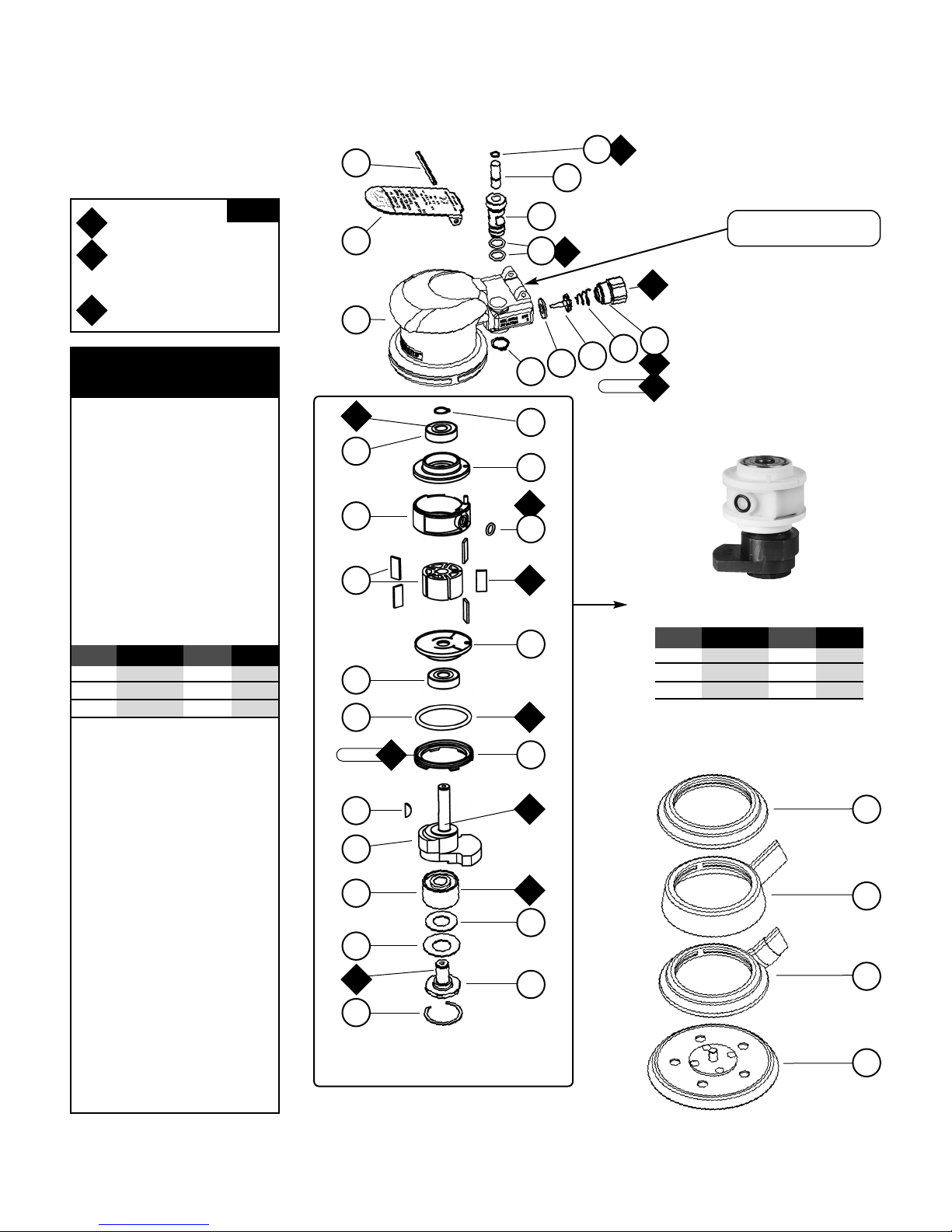
Dynorbital-Spirit
™
Complete Assembly
4
23 N•m
T
Note: To order replacement parts specify the Model # and Serial # of your machine.
A
8
O
1
O
1
O
1
A
2
A
1
A
1
O
1
O
1
A
1
O
1
Index Key
No. Part # Description
1
2
3
4
19
14
15
18
16
15
14
13
12
11
10
9
8
7
6
5
28
20
23
22
21
25
26
29
30
O
T
A
Oil: O
1
= Air Lube
Adhesive: A
1
= Loctite #609
A
2
= Loctite #271
A8= Loctite #567
Torque: N•m x 8.85 = In. - lbs.
KEY
23 N•m
T
See page 5 for Machine
Exhaust Assemblies.
31
Highly Recommended
Drop-in Complete Motor Assemblies
Orbit 3" & 3-1/2" 5" 6"
3/8" 59450 59453 59456
3/16" 59451 59454 59457
3/32" 59452 59455 59458
Orbit 3" & 3-1/2" 5" 6"
3/8" 59070 59071 59072
3/16" 59060 59061 59062
3/32" 59065 59066 59067
All above parts are included in Drop-in Motors.
Note: 59058 Lock Ring only included with
3/8" Orbit Drop-in Motors.
For assembly instructions, see page 6.
For Models:
59000, 59001, 59002, 59003, 59004, 59005, 59006
59007, 59008, 59009, 59010, 59011, 59012, 59013
59014, 59015, 59016, 59017, 59018, 59019, 59020
59059, 59022, 59023, 59024, 59025, 59026, 59027
59028, 59029, 59030, 59031, 59032, 59033, 59034
59035, 59036, 59037, 59038, 59039, 59040, 59041
59042, 59043, 59044, 59100, 59101, 59102, 59103
59104, 59105, 59106, 59107, 59108, 59109, 59110
59111, 59112, 59113, 59114
17
24
27
1 Sanding Pads (See Pg. 10)
2 Vacuum Lip-Seal Shroud
57089 5" & 6"
3 Vacuum Shroud
57084 3 1/2"
4 Shroud (Non-Vac)
54458 3-1/2"
56051 5" & 6" (Lip Seal)
5 95630 Snap Ring
6 59059 Balancer Shaft
7 95628 Washer
8 56053 Bearing Seal
9 56052 Bearing
10 Motor Shaft Balancer
11 98461 Key
12 59058 Lock Ring
13 50659 O-Ring
14 58368 Bearing (2)
15 59055 Bearing Plate (2)
16 57113 Rotor/Blade Set
17 01024 O-Ring
18 59051 Cylinder
19 98463 Retaining Ring
20 95697 Retaining Ring
21 Housing (See Chart, Pg. 6)
22 59052 Throttle Lever
23 98927 Pin
24 98459 O-Ring
25 58363 Valve Stem
26 58364 Speed Regulator
27 01025 O-Ring (2)
28 01464 Seal
29 58365 Tip Valve
30 01468 Spring
31 01494 Inlet Bushing
 Loading...