

Page 1
VACUUM OVERSKIRTS
96425
Screw (4)
95886
Washer (4)
O
1
O
1
O
1
O
1
G
1
A
3
G
1
O
1
O
1
3 N•m
T
3 N•m
T
3 N•m
T
9 N•m
T
34 N•m
T
SANDING PADS
57763 - 6" Vac (6 Hole)
57766 - 6" Vac (8 Hole)
57760 - 5" Non-Vac
57762 - 6" Non-Vac
56234 - 8" Non-Vac
56235 - 8" Vac
HOUSING MODEL
ASSEMBLY # NUMBER
64462 58441
64463 58442
64464 58443
64465 58444
64466 58445
64467 58446
1
2
3
4
5
6
9
10
11
12
14
15
17
19
20
21
22
7
8
23
24
27
26
29
30
31
32 33
35
38
39
Parts Page Reorder No. PD04•06
Effective January, 2004
Always operate, inspect and maintain this tool in accordance with the Safety Code for portable air tools
(ANSI B186.1) and any other applicable safety codes and regulations. Please refer to Dynabrade
’
s
Warning/Safety Operating Instructions for more complete safety information.
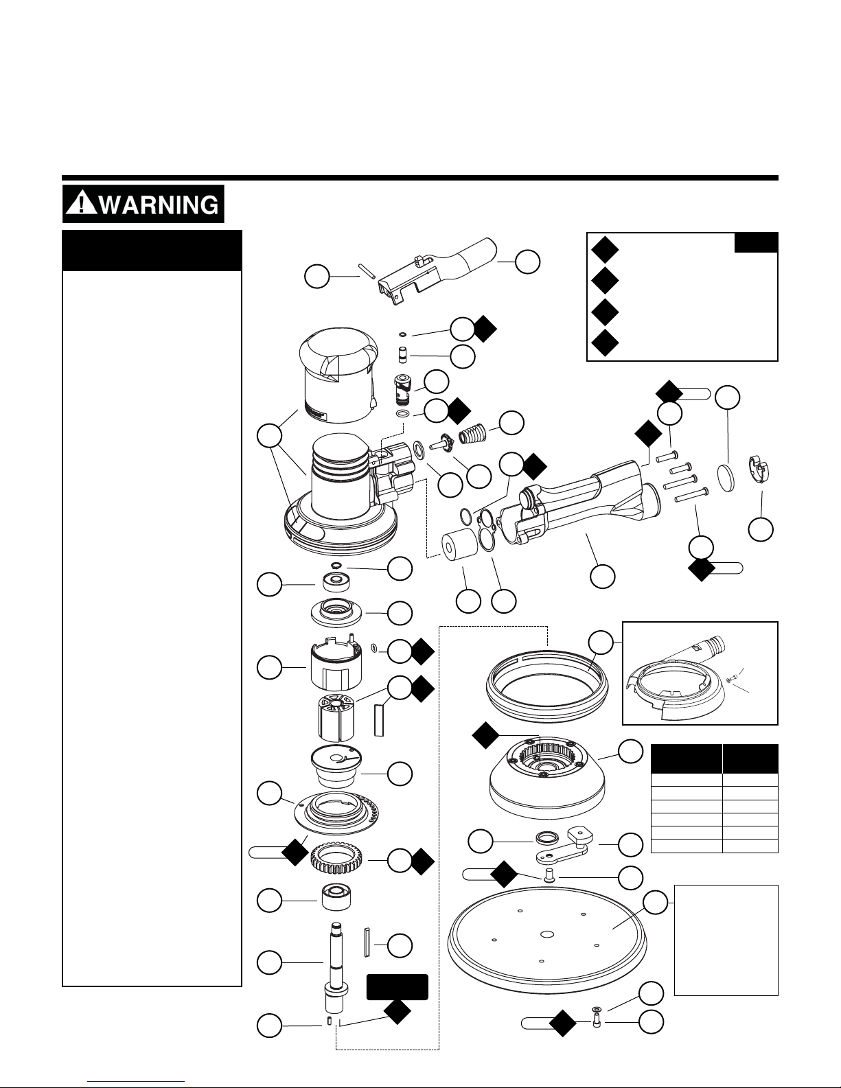
900 RPM Air Motor and Machine Parts
5", 6" & 8" 2-Hand
Gear Driven Sander
Models:
58441 -
5" Pad, 3/16" Orbit, Non-Vac
58442 -
6" Pad, 3/16" Orbit, Non-Vac
58443 -
6" Pad, 3/16" Orbit, Central Vac (6 Hole Pad)
58444 -
6" Pad, 3/16" Orbit, Central Vac (8 Hole Pad)
58445 -
8" Pad, 3/16" Orbit, Non-Vac
58446 -
8" Pad, 3/16" Orbit, Central Vac
1 95178 Screw (5)
2 95886 Washer (5)
3 Sanding Pad: See Chart
4 96477 Screw
5 Balance Arm Assembly:
56476 5" & 6"
56478 8"
6 56474 Balancer Washer
7 56470 Mount Plate Assembly
8 Shroud:
57328 Non-Vacuum
57744 6" Vacuum Overskirt
57736 8" Vacuum Overskirt
9 01673 Pin
10 56589 Shaft
11 54673 Key
12 56052 Bearing
13 56473 Pinion Gear
14 57332 Lock Ring
15 56594 Front Bearing Plate
16 54705 Rotor/Blade Set (5/pkg.)
17 56595 Cylinder
(Includes: 95865 Pin)
18 01020 O-Ring
19 54629 Rear Bearing Plate
20 01206 Bearing
21 95626 Retaining Ring
22 Housing: See Chart
(Incudes: 56581 Housing Grip
and Labels)
23 95627 Pin
24 56582 Safety Throttle Lever
25 98459 O-Ring
26 56579 Valve Stem
27 56578 Speed Regulator
28 01025 O-Ring (3)
29
56598 Seal
30 51944 Tip Valve
31 51943 Spring
32 56586* Vacuum Plug
33 56469 Exhaust Gasket
34 96459 O-Ring
35 56468 Handle Assembly
(Includes: 51938 Screen)
36 96469 Screw (2)
37 96454 Screw (2)
38 56597* Muffler
39 56596* Muffler Clip
Index Key
No. Part # Description
Adhesive: A
3
= Loctite #243
Torque: N•m x 8.85 = In. - lbs.
Grease: G
1
= Lubriplate 630 AA
Oil: O
1
= Air Lube
O
A
T
G
KEY
25
28
34
16
18
13
36
37
*Parts included with Non-Vacuum
Models Only.
Apply To
I.D. Of Threads
Page 2

Important Operating, Maintenance and Safety Instructions
Carefully read all instructions before operating or servicing any Dynabrade
®
Abrasive Power Tool.
Warning: Hand, wrist and arm injury may result from repetitive work motion and overexposure to vibration.
Important: All Dynabrade rotary vane air tools must be used with a Filter-Regulator-Lubricator to maintain all warranties.
Operating Instructions:
Warning: Eye, face, respiratory, sound and body protection must be worn while operating power tools. Failure to do so may result in serious injury or death.
Follow safety procedures posted in workplace.
1. With power source disconnected from tool, securely fasten abrasive/accessory on tool.
2. Install air fitting into inlet bushing of tool. Important: Secure inlet bushing of tool with a wrench before attempting to install the air fitting to avoid damaging
valve body housing.
3. Connect power source to tool. Be careful not to depress throttle lever in the process.
4. Air tools are not intended for use in explosive atmospheres and are not insulated for contact with electrical power sources. Sanding/Grinding certain materials can create
explosive dust. It is the employers responsibility to notify the user of acceptable dust levels. Sanding/Grinding can cause sparks which can cause fires or explosions.
It is the users responsibility to make sure the work area is free of flammable materials.
Maintenance Instructions:
1. Check tool speed regularly with a tachometer. If tool is operating at a higher speed than the RPM marked on the tool, the tool should be serviced to correct
the cause before use.
2. Some silencers on air tools may clog with use. Clean and replace as required.
3. All Dynabrade rotary vane air motors should be lubricated. Dynabrade recommends one drop of air lube per minute for each 20 SCFM (example: if the tool
specifications state 40 SCFM, set the drip rate of your filter-lubricator at 2 drops per minute). Dynabrade Air Lube (P/N 95842: 1 pt. 473 ml.) is recommended.
4. It is strongly recommended that all Dynabrade rotary vane air tools be used with a Filter-Regulator-Lubricator to minimize the possibility of misuse due to unclear air, wet
air or insufficient lubrication. Dynabrade recommends the following: 11405 Air Line Filter-Regulator-Lubricator — Provides accurate air pressure regulation, two-stage
filtration of water contaminants and micro-mist lubrication of pneumatic components. Operates 40 SCFM @ 100 PSIG has 3/8" NPT female ports.
5. Use only genuine Dynabrade replacement parts. To reorder replacement parts, specify the Model #, Serial #, and RPM of your machine.
6. A Motor Tune-Up Kit (P/N 98221) is available which includes assorted parts to help maintain motor in peak operating condition. Please refer to Dynabrade's Preventative
Maintenance Schedule for a guide to expectant life of component parts.
7. Mineral spirits are recommended when cleaning the tool and parts. Do not clean tool or parts with any solvents or oils containing acids, esters, keytones, chlorinated
hydrocarbons or nitro carbons.
8. DO NOT clean or maintain air tools with chemicals that have a low flash point (example: WD-40
®
).
9. Use the 95541 Grease Gun to apply 2 full plunges of the 95542 Grease through the grease fitting that is located in the 56470 Mount Plate Assembly.
Two full plunges of grease should be applied after every 300-hour interval of use.
Full One Year Warranty
Following the reasonable assumption that any inherent defect which might prevail in a product will become apparent to the user within one year from the date of purchase, all equipment of our
manufacture is warranted against defects in workmanship and materials under normal use and service. We shall repair or replace at our factory, any equipment or part thereof which shall,
within one year after delivery to the original purchaser, indicate upon our examination to have been defective. Our obligation is contingent upon proper use of Dynabrade tools in accordance
with factory recommendations, instructions and safety practices. It shall not apply to equipment which has been subject to misuse, negligence, accident or tampering in any way so as to affect
its normal performance. Normally wearable parts such as bearings, contact wheels, rotor blades, etc., are not covered under this warranty.
•
Important: User of tool is responsible for following accepted safety codes such as those published by the American National Standards Institute (ANSI).
•
Always disconnect power supply before changing abrasive/accessory or making machine adjustments.
•
Inspect abrasives/accessories for damage or defects prior to installation on tools.
•
Please refer to Dynabrade’s Warning/Safety Operating Instructions Tag (Reorder No. 95903) for more complete safety information.
Notice
All Dynabrade motors use the highest quality parts and metals available and are machined to exacting tolerances. The failure of quality pneumatic motors can most often be traced to
an unclean air supply or the lack of lubrication. Air pressure easily forces dirt or water contained in the air supply into motor bearings causing early failure. It often scores the cylinder
walls and the rotor blades resulting in limited efficiency and power. Our warranty obligation is contingent upon proper use of our tools and cannot apply to equipment which has been
subjected to misuse such as unclean air, wet air or a lack of lubrication during the use of this tool.
Safety Instructions:
Products offered by Dynabrade should not be converted or otherwise altered
from original design without expressed written consent from Dynabrade, Inc.
Model Motor Motor Pad Dia. Sound Maximum Air Flow Hose I.D. Size Air Inlet Weight Length Height
Number HP (W) RPM Inch (mm) Level CFM/SCFM (LPM) Inch (mm) Thread Pound (kg) Inch (mm) Inch (mm)
58441 .45 (336) 900 5 (127) 79 dB(A) 3/23 (651) 1/4 (8) 1/4" NPT 3.6 (1.7) 11-1/16 (281) 5-10/16 (143)
58442 .45 (336) 900 6 (152) 78 dB(A) 3/23 (651) 1/4 (8) 1/4" NPT 3.6 (1.7) 11-1/2 (293) 5-5/8 (141)
58443 .45 (336) 900 6 (152) 79 dB(A) 3/23 (651) 1/4 (8) 1/4" NPT 3.8 (1.7) 11-1/2 (293) 5-5/8 (141)
58444 .45 (336) 900 6 (152) 80 dB(A) 3/23 (651) 1/4 (8) 1/4" NPT 3.8 (1.7) 11-1/2 (293) 5-5/8 (141)
58445 .45 (336) 900 8 (203) 80 dB(A) 3/23 (651) 1/4 (8) 1/4" NPT 3.9 (1.8) 12-1/2 (319) 5-9/16 (142)
58446 .45 (336) 900 8 (203) 81 dB(A) 3/23 (651) 1/4 (8) 1/4" NPT 4.3 (2.0) 12-1/2 (319) 5-9/16 (142)
Additional Specifications: Air Pressure 90 PSIG (6.2 Bar)
Machine Specifications
Page 3

Disassembly/Assembly Instructions
Important: The manufactures warranty is void if the tool is disassembled before the warranty expires. Use these instructions in conjunction with the Part Number
96283 Tool Repair Kit. This kit includes special tooling for the proper disassembly/assembly of the Two-Hand Gear Driven Sander. This Tooling will be referred to in
these instructions. An air motor Tune-Up Kit, Part Number 98221 is also available. It contains the high and medium wear components that most
commonly need replacement.
Motor Disassembly:
1. Disconnect the sander from the air supply.
2. Use the 57092 Repair Collar to hold the sander in a vise. Position the sander so that the sanding pad is facing up. Note: Do not over tighten the collar and sander in the
vise. Only hold the sander snugly, so that the motor lock ring can be removed easily.
3. Use a 9/64" hex key wrench to remove the screws and sanding pad from the sander.
4. Use a 5/32" hex key wrench to remove the balance arm assembly by turning the hex key counterclockwise.
5. Remove the 56474 Balance Washer and 56470 Mount Plate Assembly.
6. Use the 56599 Lock Ring Tool to remove the 57332 Lock Ring by turning it counterclockwise.
7. Pull the air motor assembly out of the housing.
8. Use retaining ring pliers to remove the 95626 Retaining Ring.
9. Remove the 01020 O-Ring from the 56595 Cylinder and fasten a 2" bearing separator around the part of the cylinder that is closest to the 54629 Rear Bearing Plate.
10. Place the air motor with the bearing separator attached, onto the table of the 96232, #2 Arbor Press so that the balance end of the 56589 Shaft is pointing down.
11. Use a 5/16" dia. flat end drive punch as a press tool to push the shaft out of the 01206 Bearing. Use the 96213 Bearing Removal Tool (bearing removal tool not included
in the 96283 Repair Kit) to push the 01206 Bearing out of the 54629 Rear Bearing Plate.
12. Remove the cylinder, rotor, vanes, and key.
13. Use the arbor press to push 56052 bearing and the 56589 Shaft out of the 56594 Front Bearing Plate.
14. Use a 2" bearing separator and arbor press to remove the 56052 Bearing from the 56589 Shaft.
15. Use a 2" bearing separator and arbor press to remove the 56473 Pinion Gear from the 56594 Front Bearing Plate.
Motor Disassembly Complete.
Motor Assembly:
Important: Clean and inspect all motor parts for wear or defect.
1. Orient the open side of the 56052 Bearing toward the balance end of the 56589 Shaft.
2. Use the small end of the 50791 Bearing Press Tool and the 96232, #2 Arbor Press to push the 56052 Bearing onto the shaft until the I.D. of the bearing sits against the
shaft step. (Drawing 1)
3. Install the 57332 Lock Ring onto the 56594 Front Bearing Plate so that the threaded portion of the lock ring sits against the bearing plate.
4. Use the arbor press to press the 56473 Pinion Gear onto the front bearing plate. Note: Press the pinion gear onto the bearing plate so that the edge of the bearing plate
stands slightly above the pinion gear.
5. Use the large end of the 57091 Bearing press Tool and the arbor press to install the front bearing plate onto the 56052 Bearing. (Drawing 2)
6. Install the 54673 Key so that the 90° side of the key fits into the keyway of the shaft and the tapered side of the key fits into the rotor. Install the 54705 Rotor/Blade Set (5)
onto the shaft
7. Apply the 95842 Dynabrade Air Lube (10W/NR or equivalent) to the blades.
8. Install the 56595 Cylinder over the rotor so that the short line-up pin fits into the front bearing plate.
9. Place the 54629 Rear Bearing Plate over the shaft so that the long line-up pin fits through the hole in the rear bearing plate.(Drawing 3) Use the small end of the 57091
Bearing Press Tool to install the 01206 Bearing onto the shaft and into the 54629 Rear Bearing Plate. Use the press tool and the arbor press to install these so that there
is a snug fit between the bearing plates and the cylinder. Note: Carefully press the 01206 Bearing onto the motor shaft until it touches against the bearing seat on the
inside of the bearing plate. (Drawing 4)
10. Use retaining ring pliers to install the 95626 Retaining Ring so that the concave side of the ring is toward the motor assembly. Note: Be sure that the retaining ring is
completely pressed down into the groove on the shaft.
11. Use the 57092 Repair Collar to hold the housing in a vise so that the opening for the housing is facing up.
12. Apply a small amount of petroleum lubricant to the 01020 O-Ring and install the o-ring into the air inlet hole in the cylinder.
13. Install the motor assembly into the housing making sure to align the line-up pin with the line-up hole that is on the inside of the housing.
14. Use the 56599 Lock Ring Tool to secure the motor in the housing. (Torque to 34 N·m/300 in. lbs.)
15. Install the appropriate shroud onto the housing.
16. Apply a small mount of the 95542 Grease to the mount plate gear and then install the 56470 Mount Plate Assembly and the 56474 Balance Washer onto the 56589 Shaft.
Apply a small amount of the Loctite #243 (or equivalent) to the I.D. threads of the 56589 Shaft. Hold the balance arm assembly stationary with an adjustable wrench and
use a 5/32" hex key to tighten the 96477 Screw by turning it clockwise. (Torque to 9N·m/80 in. lbs.)
17. Use the 95541 Grease Gun to apply 2 full plunges of the 95542 Grease through the grease fitting that is located in the 56470 Mount Plate Assembly. Two full plunges of
grease should be applied after every 300-hour interval of use.
18. Use a 9/64" hex key wrench to install a weight-mated sanding pad.
Motor Assembly Complete.
Handle and Valve Disassembly:
1. Place the 57092 Repair Collar around the housing so that the handle is pointing up.
2. Use a Phillips screwdriver to remove the four screws that fasten the handle to the housing. Carefully pull the handle from the housing. This provides access to the tip
valve components, also the handle o-ring, gasket and vacuum plug.
3. Use a 1/8" dia. flat end drive punch to remove the 95627 Pin and the 56582 Safety Throttle Lever.
4. Pull the 56578 Speed Regulator and valve stem out of the housing.
Handle and Valve Disassembly Complete.
Handle and Valve Assembly:
1. Place the 57092 Repair Collar around the housing so that the handle mounting area is facing up.
2. Install the 01025 O-Rings (3) onto the 56578 Speed Regulator, apply a small amount of petroleum lubricant to the o-rings and insert the regulator assembly into the
housing. Note: Be careful that the o-rings do not get caught and pulled out of the o-ring grooves.
(continued text and diagrams on next page)
Page 4

DYNABRADE
®
DYNABRADE, INC.,
8989 Sheridan Drive •Clarence, NY 14031-1490 •Phone: (716) 631-0100 •Fax: 716-631-2073 •International Fax: 716-631-2524
DYNABRADE EUROPE S.àr.l.,
Zone Artisanale •L-5485 Wormeldange—Haut, Luxembourg •Telephone: 352 76 84 94 1 •Fax: 352 76 84 95 1
© DYNABRADE, INC., 2004 PRINTED IN USA PD04.06_Rev.2_04/05
Visit Our Web Site: www.dynabrade.com Email: Customer.Service@Dynabrade.com
98221 Motor Tune-Up Kit
•
Includes assorted parts to
help maintain and repair motor.
96232 (#2) Arbor Press
•
This arbor press is ideal for the disassembly
and assembly of air motors.
96346 2" Bearing Separator
•
Use the separator to remove gears
and bearings.
Dynabrade Air Lube
•
Formulated for pneumatic equipment.
•
Absorbs up to 10% of its weight in water.
•
Prevents rust and formation of sludge.
•
Keeps pneumatic tools operating longer
with greater power and less down time.
95842: 1pt. (473 ml)
95843: 1 gal. (3.8 L)
Diagrams
Optional Accessories
3. Install the 98459 O-Ring onto the 56579 Valve Stem, apply a small amount of petroleum lubricant to the o-ring and insert the shortest portion (from the end to the o-ring) of
the valve stem assembly into the speed regulator.
4. Install the 56582 Safety Throttle Lever onto the housing and secure it in place with the 95627 Pin.
5. Install the 56598 Seal into the air inlet passage of the housing.
6. Install the 56586 Vacuum Plug into the exhaust passage of the housing. (See Exploded View)
7. Use needle-nose pliers to grasp and install the 51944 Tip Valve so that it fits under the 56579 Valve Stem.
8. Install the large end of the 51943 Spring into the air inlet passage of the handle.
9. Install the 56469 Gasket onto the mounting surface of the handle.
10. Install the 96459 O-Ring onto outside diameter of the air inlet passage at the location of the first shoulder and apply a small amount of petroleum lubricant to the o-ring.
11. Connect the handle to the housing and secure it in place with the four screws. Note: The two longer screws, Part Number 96454 (2) secure the 56581 Grip to the housing.
12. Install the 56597 Muffler and secure it in place with the 56596 Muffler Clip. (See Exploded View)
Handle and Valve Assembly Complete. Tool Assembly Complete. Please allow 30 minutes for adhesives to cure before operating tool.
Important: Motor should now be tested for proper operation at 90 PSIG. If motor does not operate properly or operates at a higher RPM than marked on the tool, the tool should
be serviced to correct the cause before use. Before operating, place 2-3 drops of Dynabrade Air Lube (P/N 95842) directly into air inlet with throttle lever depressed. Operate tool
for 30 seconds to determine if tool is operating properly and to allow lubricating oils to properly penetrate motor.
Loctite®is a registered trademark of Loctite Corp.
Drawing 1 Drawing 2
02695 Bearing
Drawing 3 Drawing 4
57091
Bearing Press Tool
57091
Bearing Press Tool
57091
Bearing Press Tool
01206
Bearing
Cylinder w/Front
Bearing Plate,
Lock Ring,
Pinion Gear
and Shaft
56595
Cylinder
54629
Rear Bearing Plate
Lock Ring and
Pinion Gear
Lock Ring,
Pinion Gear
and Shaft
56052
Bearing
96283 Motor Repair Kit:
•
Contains special tools for
disassembly/assembly of machine.
56589
Shaft
56052
Bearing
96213 Bearing Removal Tool
•
This tool is used to pass through the I.D.
of the bearing plate and to push against
the I.D. of the bearing.
96343 Retaining Ring Pliers
•
Internal/external retaining ring pliers.
Tip diameter - 0.038" (0.96mm)
95134 – 9/64" Hex Wrench
95135 – 5/32" Hex Wrench
 Loading...