

Dynabrade Dynafine 10800, Dynafine 10810, Dynafine 10820, Dynafine 10821, 57900 Safety, Operation And Maintenance Manual
...Page 1

Parts Page Reorder No. APD08•02
Effective January, 2008
Supersedes APD97•08
Dynafine®Sanders
Detail Sander/Finger/Wet
Air Tool Manual – Safety, Operation and Maintenance
Models: (Sander)
10800 – 13,000 RPM, Detail Sander
10810 – Detail Sander Versatility Kit
10820 – 13,000 RPM, Finger Sander
10821 – Finger Sander Versatility Kit
Model: (Wet)
10880 – 13,000 RPM, Wet Sander
SAFETY LEGEND
G
Read and understand tool manual before
work starts to reduce risk of injury to
operator, visitors, and tool.
Eye protection must be worn at all times,
eye protection to conform to ANSI Z87.1.
Respiratory protection to be used when exposed to
contaminants that exceed the applicable threshold
limit values required by law.
Practice safety requirements. Work alert,
have proper attire, and do not operate tools under
the influence of alcohol or drugs.
Ear protection to be worn when exposure to sound,
exceeds the limits of applicable Federal, State or
local statues, ordinances and/or regulations.
Air line hazard, pressurized supply lines and flexible
hoses can cause serious injury. Do not use damaged,
frayed or deteriorated air hoses and fittings.
Read and understand this tool manual before operating your air tool. Follow all safety rules for the protection of operating personnel
as well as adjacent areas. Always operate, inspect and maintain this tool in accordance with the American National Standards
Institute (ANSI) Safety Code for Portable Air Tools – B186.1. For additional safety information, refer to Safety Requirements for the
Use, Care and Protection of Abrasive Wheels – ANSI B7.1, Code of Federal Regulation – CFR 29 Part 1910, European Committee for
Standards (EN) Hand Held Non-Electric Power Tools – Safety Requirements and applicable State and Local Regulations.
SAFETY INSTRUCTIONS
Carefully Read all instructions before operating or servicing any Dynabrade
®
Abrasive Power Tool.
Products offered by Dynabrade are not to be modified, converted or otherwise altered from the original design without expressed written
consent from Dynabrade, Inc.
Tool Intent: Dynafine
®
Sanders are designed for finishing. Excellent for removing milling and machining marks from wood, solid surface and metal. Defect
removal in painted surfaces and clear coats.
Do Not use tool for anything other than its intended applications.
This power tool is not intended for use in potentially explosive atmospheres and is not insulated against contact with electrical power.
Training: Proper care, maintenance, and storage of your tool will maximize its performance.
• Employer's Responsibility – Provide Dynafine
®
operators with safety instructions and training for safe use of tools and accessories.
(continued on next page)
SAVE THIS DOCUMENT, EDUCATE ALL PERSONNEL
FIND THE MOST CURRENT OFFERING OF ACCESSORIES AND SUPPORT DOCUMENTS @ WWW.DYNABRADE.COM
Some dust created by sanding, grinding, drilling, and other construction activities contain chemicals known to cause cancer, birth
defects or other reproductive harm. Some examples of these chemicals are:
• Lead from lead-based paints
• Crystalline silica from bricks and cement and other masonry products
• Arsenic and chromium from chemically treated lumber
Your risk from these exposures varies, depending on how often you do this type of work. To reduce your exposure to these chemicals: work
in a well ventilated area, and work with approved safety equipment, such as those dust masks that are specially designed to filter out
microscopic particles.
Model 10800
AUTOMOTIVE
WARNIN
WARNING
WARNING
WARNING
WARNING
WARNING
WARNING
WARNING
Page 2
SAFETY INSTRUCTIONS - Cont.
Accessory Selection:
• Abrasive/accessory RPM (speed) rating MUST be approved for AT LEAST the tool RPM rating.
• Before mounting an accessory, visually inspect for defects. Do not use defective accessories.
• Mount only recommended accessories. See back page of manual and Dynabrade literature.
• Follow tool specifications before choosing size and type of accessory.
• Only use recommended fittings and air line sizes. Air supply hoses and air hose assemblies must have a minimum working pressure rating of 150 PSIG
(10 bars, g) or 150 percent of the maximum pressure produced in the system, whichever is higher. (See tool Machine Specifications table.)
OPERATING INSTRUCTIONS
Warning: Always wear personal protection equipment. Operator of tool is responsible for following: accepted eye, face, respiratory, hearing and
body protection. Adjacent personnel must be protected from potential injury.
Caution: Hand, wrist and arm injury may result from repetitive work, motion and overexposure to vibration.
• Keep hand and clothing away from working end of the air tool.
Operation: Be sure that any loose clothing, hair and all jewelry is properly restrained.
• Secure inlet bushing on air tool with a wrench before attempting to install the air fitting to avoid damaging housing assembly.
• Check tool RPM (speed) with tachometer with air pressure set at 90 PSIG (6.2 Bars, g) while the tool is running. If tool is operating at a higher speed than
the RPM marked on the tool housing, or operating improperly, the tool must be serviced and corrected before use.
Caution: Tool RPM must never exceed abrasive/accessory RPM rating. Check accessory manufacturer for details on maximum operating speed or special
mounting instructions.
• With power source disconnected from air tool, mount recommended accessory.
• Connect air tool to power source. Be careful NOT to depress throttle lever in the process.
Do not expose air tool to inlet pressure above 90 PSIG or (6.2 Bars, g).
Caution: After installing the accessory, the tool must be started at a reduced speed to check for good balance.
Gradually increase tool speed. DO NOT USE if tool vibration is excessive. Correct cause, and retest to insure safe operation.
• Make sure that work area is uncluttered, and visitors are at a safe range from the tools and debris.
• Use a vise or clamping device to hold work piece firmly in place.
• Do not apply excessive force on tool or apply “rough” treatment to it.
• Always work with a firm footing, posture and proper lighting.
Report to your supervisor any condition of the tool, accessories, or operation you consider unsafe.
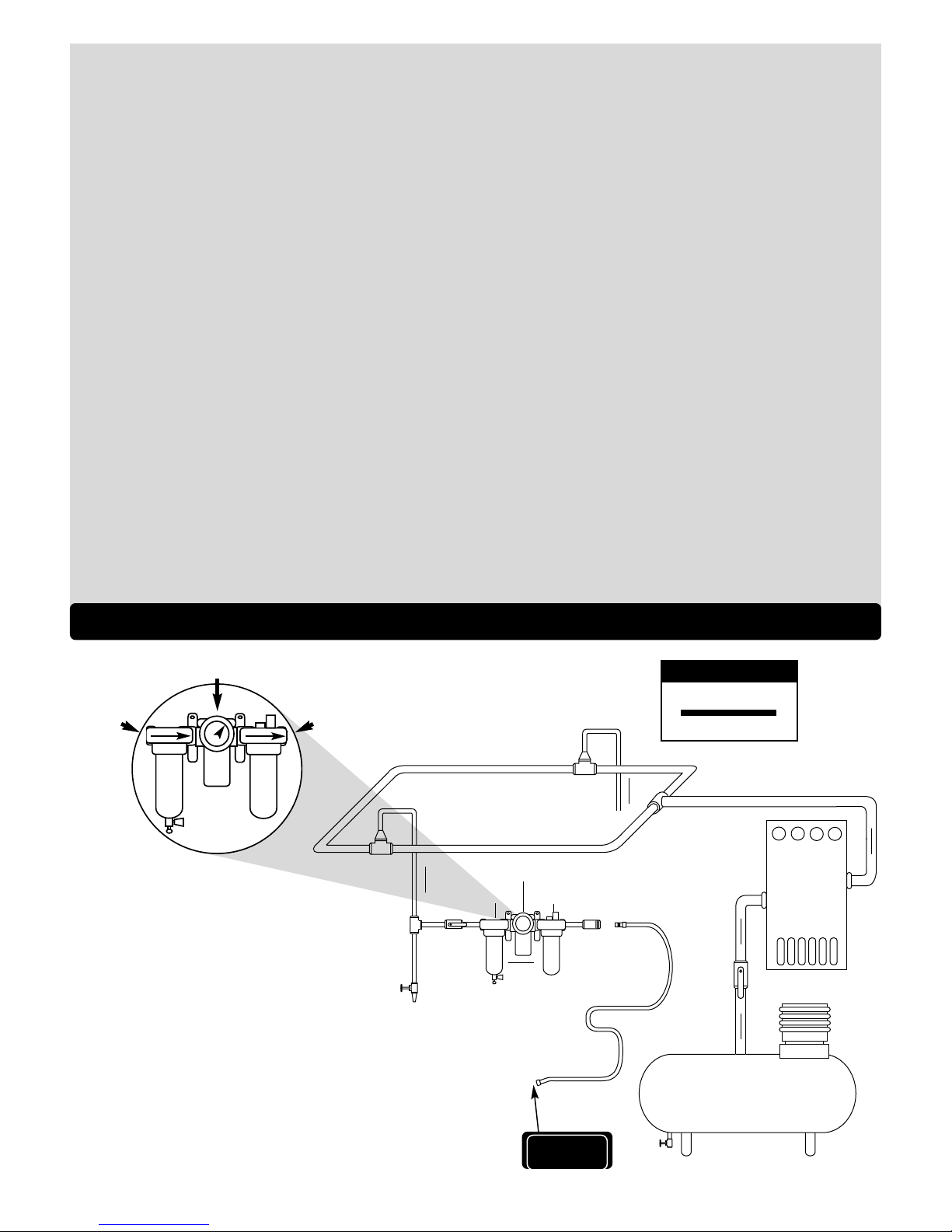
To Tool Station
Closed Loop Pipe System
(Sloped in the direction of air flow)
Ball
Valve
Ball
Valve
Filter
Regulator
Lubricator
Air Flow
Drain
Valve
Drain
Valve
Air Tool
Air Compressor
and Receiver
Drain
Valve
Air Hose
Air Flow
Refrigerated
Air Dryer
2
Filter
Regulator
Lubricator
90 PSIG
(6.2 Bar, g)
Air System
1 DROP/MIN.
20 SCFM
LUBRICATOR SETTING
•
Dynabrade Air Power Tools are designed to
operate at 90 PSIG (6.2 Bar/620 kPa) maximum
air pressure at the tool inlet, when the tool is
running. Use recommended regulator to control
air pressure.
•
Ideally the air supply should be free of moisture.
To facilitate removing moisture from air supply, the
installation of a refrigerated air dryer after the
compressor and the use of drain valves at each
tool station is recommended.
➤
➤
➤
➤
➤
➤
90 PSIG MAX
(6.2 Bar, g)
Page 3

Maintenance Instructions
Important:A preventative maintenance program is recommended whenever portable power tools are used.
•
Use only genuine Dynabrade replacement parts to insure quality. To order replacement parts, specify Model#, Serial# and RPM of your air tool.
•
It is strongly recommended that all Dynabrade rotary vane air tools be used with a Filter-Regulator-Lubricator to minimize the possibility of misuse due
to unclean air, wet air or insufficient lubrication. Dynabrade recommends the following: 11411 Air Filter-Regulator-Lubricator (FRL) – Provides accurate
air pressure regulation and two stage filtration of water contaminants. Operates 55 SCFM/1,558 LPM @ 90 PSIG (6.2 Bar, g) with 1/2" NPT female ports.
•
Dynabrade recommends one drop of air lube per minute for each 20 SCFM/566 LPM (example: if the tool specification states 40 SCFM/1133 LPM, set
the drip rate on the filter-lubricator to 2 drops per minute). Dynabrade Air Lube (P/N 95842: 1 pt 473 ml) is recommended.
Routine Preventative Maintenance: Check free speed of tool using a tachometer. This tool should be speed checked on a regular basis.
•
Mineral spirits are recommended when cleaning the tool and parts. Do not clean tool or parts with any solvents or oils containing acids, esters,
ketones, chlorinated hydrocarbons or nitro carbons.
•
DO NOT clean or maintain tools with chemicals that have a low flash point (example: WD-40
®
).
•
A Motor Tune-Up Kit (P/N 96236) is available which includes high wear and medium wear motor parts.
•
Air tool labels must be kept legible at all times, if not, reorder label(s) and replace. User is responsible for maintaining specification information i.e.:
Model #, S/N, and RPM. (See Assembly Breakdown)
•
Blow air supply hose out prior to initial use.
•
Visually inspect air hoses and fittings for frays, visible damage and signs of deterioration. Replace damaged or worn components.
•
Refer to Dynabrade's Warning/Safety Operating Instructions Tag (Reorder No. 95903) for safety information.
After maintenance is performed on tool, add a few drops of Dynabrade Air Lube (P/N 95842) to the air line and start the tool a few times to lubricate air motor.
Check for excessive tool vibration.
Handling and Storage:
•
Use of tool rests, hangers and/or balancers is recommended.
•
Protect tool inlet from debris (see Notice below).
•
DO NOT carry tool by air hose or near the tool throttle lever.
•
Protect abrasive accessories from exposure to water, solvents, high humidity, freezing temperature and extreme temperature changes.
•
Store accessories in protective racks or compartments to prevent damage.
Notice
All Dynabrade motors use the highest quality parts and metals available and are machined to exacting tolerances.The failure of quality pneumatic motors
can most often be traced to an unclean air supply or the lack of lubrication.Air pressure easily forces dirt or water contained in the air supply into motor
bearings causing early failure.It often scores the cylinder walls and the rotor blades resulting in limited efficiency and power.Our warranty obligation is
contingent upon proper use of our tools and cannot apply to equipment which has been subjected to misuse such as unclean air, wet air or a lack of
lubrication during the use of this tool.
One Year Warranty
Following the reasonable assumption that any inherent defect which might prevail in a product will become apparent to the user within one year from the
date of purchase, all equipment of our manufacture is warranted against defects in workmanship and materials under normal use and service.We shall
repair or replace at our factory, any equipment or part thereof which shall, within one year after delivery to the original purchaser, indicate upon our
examination to have been defective.Our obligation is contingent upon proper use of Dynabrade tools in accordance with factory recommendations,
instructions and safety practices.It shall not apply to equipment which has been subject to misuse, negligence, accident or tampering in any way so as to
affect its normal performance.Normally wearable parts such as bearings, contact wheels, rotor blades, etc., are not covered under this warranty.
Machine Specifications
3
Model Motor Motor Sound Air Flow Rate Air Pressure Weight Length Height
Number hp (W) RPM Level SCFM (LPM) PSIG (Bars) Pound (kg) Inch (mm) Inch (mm)
10800/10810 .15 (118) 13,000 65 dB(A) 20 (566) 90 (6.2) 1.6 (.7) 9 (229) 3-3/4 (95)
10820/10821 .15 (118) 13,000 65 dB(A) 20 (566) 90 (6.2) 1.6 (.7) 11-3/4 (298) 4 (102)
10880 .15 (118) 13,000 65 dB(A) 20 (566) 90 (6.2) 1.6 (.7) 9 (229) 3-3/4 (95)
Additional Specifications: Air Inlet Thread 1/4" NPT • Hose Size 1/4" (6 mm)
Sound Level is the pressure measurement according to the method outlined in ISO regulation ISO-15744
Page 4

1 97328 Screw (2)
2 57932 3/8" Sanding Arm
3 57953 Hook-Face Pad
4 58030 2" Vinyl Face Pad
58032 3" Vinyl Face Pad
5 11016 Bearing
6 57976 Boot Assembly
7 97326 Boot Clamp
8A 58095 Cam Assy. (Includes: 96238 Pin)
8B 96238 Pin
9 57962 Exhaust Cover
10 02649 Bearing
11 54529 Shim Pack (3/pkg.)
12 02038 Front Bearing Plate
13 01479 Spacer
14 01480 Blades (4/pkg.)
15 02037 Rotor
16 01476 Cylinder
17 50767 Pin
18 02673 Rear Bearing Plate
19 02696 Bearing
20 02679 Shield
21 7˚ Housing
01546 Standard
57779 Wet
22 01548 Gasket
23 01461 Lock Nut
24 01558 Collar
25 95523 O-Ring
26 01470 Insert
27 Housing
10809 Model: 10800
10829 Model: 10820
10889 Model: 10880
28 95558 Retaining Ring
29 01449
Valve Stem
30 01448 Throttle Lever
01462 Safety Lock Lever
31 12132 Pin
32 95730 O-Ring
33 01024 O-Ring
34 01469 Speed Regulator Assembly
(Includes: 95730, 01024 O-Ring)
35 01464 Seal
36 01472 Tip Valve
37 01468 Spring
38 96065 O-Ring
39 57970 Air Control Ring
40* 95438 O-Ring
41* 95711 Retaining Ring
42* 94521 Muffler Cap
43* 94528 Felt Muffler
44* 94522 Muffler Cap
45* 95375 O-Ring
46* 94526 Spacer
47* 94523 Inlet Adapter
48 94407 1/4" Flow Control Valve
49 10293 Shrink Tube
50 95955 10' Tubing
51 95962 Quick Disconnect
52 57751 Button (w/set screw)
53 97327 Screw (2)
54 95074 Hose Fitting
55 57728 Nozzle
56 57778 Bracket
57 57727 Valve Cartridge
58 95523 O-Ring
59 56076 Throttle Valve
Index Key
No. Part # Description
Adhesive: A1= Loctite #609
A
2
= Loctite #271
A
8
= Loctite #567
Torque:N•m x 8.85 = In. - lbs.
Grease:G
1
= Lubriplate 630 AA
Oil:O
1
= Air Lube
O
A
T
G
KEY
.4 hp Dynafine®Sander
Complete Assembly
4
16
17
18
19
20
58
56
57
52
22
24 25
26
34
32
33
28
29
30
31
15
35
37
38
39
44*
45*
46*
51
50
36
40*
41*
43*
42*
13
12
11
10
9
8A
8B
7
6
4
3
2
1
A
2
A
2
A
8
A
8
A
8
A
8
O
1
A
8
A
1
O
1
A
8
G
1
A
8
0.7 N•m
T
28 N•m
T
45 N•m
T
23 N•m
T
17 N•m
T
* Note: All parts indicated by an asterisk
are included in 94519 Muffler Assembly.
53
59
Apply to set screw (included)
5
14
23
27
47*
Left Hand
Threads
Right Hand
Threads
49
Parts
Included in
57777 Wet
Assembly
55
54
21
48
Page 5

Disassembly/Assembly Instructions - .4 hp Dynafine®Tools
Important: The Manufacturing Warranty is void if the tool is disassembled before the warranty expires, by anyone other than a
Dynabrade®Approved Repair Technician. Notice: A 96236 Motor Tune-Up Kit is available. Also, the special repair tooling referred to
in these instructions can be ordered through your Dynabrade
®
Distributor. Please refer to this tool manual for correct
part number identification.
Important: Always follow these steps before servicing any part of this air tool.
1. Shut off the air supply, and depress throttle lever to dissipate the remaining air. Carefully disconnect the tool from the air supply hose.
Motor Disassembly:
1. Place the 52296 Repair Collar around the 01546/57779 Housing and hold the sander in a vise with the sanding attachment facing up.
2. Use the 95266 Hex Key (3mm) to remove the sanding attachment.
3. Loosen and remove the 95884 Boot Clamp and boot assembly.
4. Use an adjustable 3mm pin spanner wrench or the 50971 Lock Ring Tool to loosen the 57962 Exhaust Cover by turning it counterclockwise.
5. Pull the air motor out of the 01546/57779 Housing. Fasten the 96346 Bearing Separator (2") around the portion of the 01476 Cylinder that is closest to
the rear bearing plate.
6. Place the bearing separator and the air motor on the table of the 96232 Arbor Press (#2) so that the cam assembly is pointing down.
7. Remove the 02679 Shield from the 02696 Bearing.
8. Use a 3/16" or 4mm diameter flat end drive punch as a press tool to push the rotor out of the 02696 Bearing.
9. Remove the cylinder and vanes.
10. Use the 96210 Bearing Removal Tool and the arbor press to remove the 02696 Bearing from the 02673 Rear Bearing Plate.
11. Hold the vane slot portion of the rotor in a vise with aluminum or bronze jaws so that the cam assembly is pointing up.
12. Use an adjustable open-end wrench to remove the cam assembly by turning it counterclockwise.
13. Remove the 02649 Bearing, 01478 Front Bearing Plate, 54529 Shims and 01479 Spacer from the rotor.
Motor Disassembly Complete.
Valve Disassembly:
1. Place the 52296 Repair Collar around the 01546/57779 Housing and hold the tool in a vise so that the inlet adapter is pointing up.
2. Use two wrenches, one to hold the inlet adapter stationary and the other to remove the air fitting.
3. Remove the inlet adapter by turning it counterclockwise. Note: Refer to the exploded view of the muffler to identify components and their
order of disassembly.
4. Use needle nose pliers to remove the 01468 Spring and the 01472 Tip Valve. Use a small screwdriver to remove the 01464 Seal.
5. Use a 2.5mm diameter drive punch to remove the 12132 Pin, and throttle lever. Remove the 01449 Valve Stem.
6. Use retaining ring pliers to remove the 95558 Retaining Ring and the 01469 Speed Regulator Assembly from the housing.
Valve Disassembly Complete.
Important: Clean and inspect all parts before assembling.
Valve Assembly:
1. Install the 01469 Speed Regulator Assembly (with o-rings) into the 01546/57779 Housing and hold it in place with the 95558 Retaining Ring.
2. Position the 52296 Repair Collar around the 01546/57779 Housing and hold the tool in a vise so that the 12132 Pin, throttle lever, and 01449
Valve Stem can be installed.
3. Position the 52296 Repair Collar around the 01546/57779 Housing and hold the tool in a vise so that the air inlet opening is pointing up.
4. Install the 01464 Seal into the air inlet so that it is laying flat.
5. Use needle nose pliers to install the 01472 Tip Valve so that the metal pin passes through the hole in the 01449 Valve Stem.
6. Install the 01468 Spring so that the smaller end of the spring fits against the back of the tip valve.
7. Apply a small amount of the Loctite
®
#567 (or equivalent) to the external threads of the inlet adapter and install it into the valve housing.
Note: Refer to the exploded view of the muffler to identify components and their order of assembly.
8. Use two wrenches, one to hold the inlet adapter stationary and the other to install the air fitting.
Valve Assembly Complete.
Motor Assembly:
1. Hold the vane slot portion of the rotor in a vise with aluminum or bronze jaws so that the threaded spindle is pointing up.
2. Install the 01479 Spacer onto the rotor.
3. Select .003" (.08mm) thickness in shims from the 54529 Shim Pack and install shims into the 02038 Front Bearing Plate.
4. Install the 02649 Bearing into the front bearing plate and onto the rotor.
5. Install the 57962 Exhaust Cover and the 58095 Cam Assembly onto the rotor. (Torque to 17 N•m/150 in. lbs.)
(continued on next page)
5
Page 6

Disassembly/Assembly Instructions - .4 hp Dynafine®Tools (Cont.)
6. Use a .001"(0.3mm) thick feeler gauge to check the clearance between the front bearing plate and the face of the rotor.
7. The clearance should be .001"-.0015" (0.3-0.4mm).
Note: If the clearance needs adjustment, repeat steps 2-5 adding or removing shims as required.
8. Lubricate the 01480 Vanes with the 95842 Dynabrade®Air Lube 10W/NR (or equivalent) and install these into the rotor.
9. Install the 01476 Cylinder over the rotor so that the air inlet opening of the cylinder will line up with the air inlet opening in the
02673 Rear Bearing Plate.
10. Use the raised outer diameter of the 96216 Bearing Press Tool and the arbor press to install the 02696 Bearing into the 02673 Rear Bearing Plate.
11. Use the raised inner diameter of the 96216 Bearing Press Tool and the arbor press to install the bearing/plate onto the rotor.
Note: Carefully press the bearing/plate down until it just touches the cylinder. This will establish a snug fit between the bearing plates and the cylinder.
12. Apply a small amount of light grease to the seal of the 02696 Bearing and adhere the 02679 Shield against the bearing.
13. Carefully slide the motor assembly into the 01546/57779 Housing.
14. Apply a small amount of the Loctite
®
#567 (or equivalent) to the threads of the 01546/57779 Housing.
15. Use a 3mm adjustable pin spanner wrench or the 50971 Lock Ring Tool to tighten the exhaust cover onto the 01546/57779 Housing.
(Torque to 28N•m/250 in. lbs.)
16. Install the 57976 Clamp onto the boot assembly.
17. Install the boot assembly with the clamp, aligning them on the 57962 Exhaust Cover. Tighten the clamp. (Torque to 7N•m/6 in. lbs.)
18. Use the 95266 Hex Key (3mm) to install the sanding attachment.
Motor Assembly Complete.
Tool Assembly Complete. Please allow 30 minutes for adhesives to cure before operating tool.
Important: Before operating , place 2-3 drops of Dynabrade Air Lube (P/N 95842) directly into inlet with throttle lever depressed. Operate tool for 30
seconds to allow air lube to properly lubricate internal motor components. Motor should now be tested for proper operation at 90 PSIG (6.2 Bar, g) max.
If tool operates at a higher RPM than marked on the tool or if vibration and sound levels seem abnormal, the tool should be serviced to correct
the cause before use.
Throttle Positioning Procedure:
Important: Carefully perform this procedure so as not to entirely separate the 01546 Housing from the valve housing. Loosen the 01461 Lock Nut
only enough to make the desired throttle lever adjustment.
1. Place the 52296 Repair Collar around the valve housing and hold it in a vise so that the 01546/57779 Housing is pointing up.
2. Slip the 01558 Collar down onto the valve housing to expose the 01461 Lock Nut.
3. With a firm hold on the 01546/57779 Housing use a 34mm or an adjustable wrench to turn the lock nut clockwise to loosen the 01546/57779 Housing
from the valve housing.
4. Orient the throttle lever to the operators desired grip and positioning. Note: Allow for additional rotation of the 01546/57779 Housing as the 01461
Lock Nut is tightened.
5. Grasp the 01546/57779 Housing firmly to reduce its rotation. Use a 34mm or an adjustable wrench to tighten the 01461 Lock Nut.
Torque to 45 N•m/400 lbs. in.
6. Slip the 01558 Collar back over the 01461 Lock Nut.
Throttle Positioning Procedure Complete.
6
Loctite®is a registered trademark of Loctite Corp.
Page 7

This service chart is published as a guide to expectant life of component parts. The replacement levels are based on average tool
usage over one year. Dynabrade Inc. considers one year usage to be 1,000 hours.
Preventative Maintenance Schedule
For All .4hp Dynafine®Sanders
Note: Please refer to page 4 of tool
manual for specific part number.
Index Part Description Number High Wear Medium Wear Low Wear Non-Wear
# Number Required 100% 70% 30% 10%
1
See Note Screw 2 L
2 57932 3/8" Sanding Arm 1 X
3 57953 Hook-Face Pad 1 X
4
See Note Vinyl Face Pad 1 X
5 11016 Bearing 1 T
6 57976 Boot Assembly 1 X
7 97326 Boot Clamp 1 X
8 58095 Cam Assembly 1 X
9 57962 Exhaust Cover 1 X
10 02649 Bearing 1 X
11 54529 Shim Pack (3/pkg.) 1 D
12 02038 Front Bearing Plate 1 X
13 01479 Spacer 1 L
14 01480 Blades 4 T
15 02037 Rotor 1 X
16 01476 Cylinder 1 X
17 50767 Pin 1 X
18 02673 Rear Bearing Plate 1 X
19 02696 Bearing 1 T
20 02679 Shield 1 T
21
See Note Housing 1 X
22 01548 Gasket 1 T
23 01461 Lock Nut 1 X
24 01558 Collar 1 D
25 95523 O-Ring 1 T
26 01470 Insert 1 X
27
See Note Housing 1 X
28 95558 Retaining Ring 1 T
29 01449 Valve Stem 1 T
30
See Note Lever 1 X
31 12132 Pin 1 T
32 95730 O-Ring 1 X
33 01024 O-Ring 1 X
34 01469 Speed Regulator Assy. 1 T
35 01464 Seal 1 T
36 01472 Tip Valve 1 T
37 01468 Spring 1 T
38 96065 O-Ring 1 T
39 57970 Air Control Ring 1 X
40* 95438 O-Ring 1 T
41* 95711 Retaining Ring 1 T
42* 94521 Muffler Cap 1 D
43* 94528 Felt Muffler 1 T
44* 94522 Muffler Base 1 D
45* 95375 O-Ring 1 T
46* 94526 Spacer 1 X
47* 94523 Inlet Adapter 1 X
48 94407 1/4" Flow Control Valve 1 X
49 10293 Shrink Tube 1 X
50 95955 10' Tubing 1 X
51 95962 Quick Disconnect 1 X
52 57751 Button (w/set screw) 1 X
53 97327 Screw 2 X
54 95074 Hose Fitting 1 X
55 57728 Nozzle 1
X
56 57778 Bracket 1 X
57 57727 Valve Cartridge 1 X
58 95523 O-Ring 1 X
59 56076 Throttle Valve 1 X
7
96236 – Motor Tune-Up Kit
LEGEND
T Included in Tune-Up Kit.
X Type of wear, no other
comments apply.
L Easily lost. Care during
assembly/disassembly.
D Easily damaged during
assembly/disassembly.
R Replace each time tool is
disassembled.
Page 8

DYNABRADE
®
DYNABRADE, INC.,
8989 Sheridan Drive •Clarence, NY 14031-1490 •Phone: (716) 631-0100 •Fax: 716-631-2073 •International Fax: 716-631-2524
DYNABRADE EUROPE S.àr.l.,
Zone Artisanale •L-5485 Wormeldange—Haut, Luxembourg •Telephone: 352 76 84 94 1 •Fax: 352 76 84 95 1
© DYNABRADE, INC., 2008 PRINTED IN USA APD08.02_01/08
Visit Our Web Site: www.dynabrade.com Email: Customer.Service@Dynabrade.com
Optional Accessories
96236 Motor Tune-Up Kit
•
Includes assorted parts to help
maintain and repair motor.
52296 Repair Collar
•
Specially designed collar for use
in vise to prevent damage to
valve body housing during
disassembly/assembly.
96210 Bearing Removal Tool
•
This tool is used to pass through
the I.D. of the bearing plate and
to push against the I.D. of
the bearing.
96216, 96243, 96244
Bearing Press Tools
•
These tools are used to safely
press a bearing plate or
onto a shaft.
Dynabrade Air Lube
•
For pneumatic equipment.
•
Absorbs up to 10% of its weight
in water.
•
Prevents rust and formation
of sludge.
95842: 1pt. (473 ml)
95843: 1 gal. (3.8 L)
50971 Lock Ring Tool
•
Lock Ring Tool has a 3/8 in.
square socket for use with 3/8 in.
drive; breaker bar, ratchet head,
or torque wrenches.
96232 #2 Arbor Press
•
This arbor press is ideal for
the disassembly and assembly
of air motors.
96346 Bearing Separator
•
Use the separator to remove
bearings and gears.
FIND THE MOST CURRENT OFFERING OF ACCESSORIES AND SUPPORT DOCUMENTS @ WWW.DYNABRADE.COM
Reference Contact Information
1. American National Standards Institute – ANSI
25 West 43
rd
Street
Forth Floor
New York, NY 10036
Tel: 1 (212) 642-4900
Fax: 1 (212) 398-0023
2. Government Printing Office – GPO
Superintendent of Documents
Attn. New Orders
P.O. Box 371954
Pittsburgh, PA 15250-7954
Tel: 1 (202) 512-1803
3. European Committee for Standardization
Rue de Stassart 36
B - 1050 Brussels, Belgium
 Loading...