

Page 1
Always operate, inspect and maintain this tool in accordance with the Safety Code for portable air tools (ANSI
B186.1) and any other applicable safety codes and regulations. Please refer to Dynabrade's Warning/Safety
Operating Instructions for more complete safety information.
Parts Page Reorder No. PD97•21
Effective March, 1997
Supercedes PD96•01
Random Orbital Sander, 3/16" Dia. Orbit.
Models:
57000 - 3-1/2" Non-Vacuum 57023 - 5" Vac-Ready w/overskirt
57001 - 3-1/2" Basic Vacuum 57024 - 5" Central Vac-Ready w/overskirt
57002 - 3-1/2" Deluxe Vacuum 57026 - 6" Non-Vacuum
57003 - 3-1/2" Vac-Ready 57027 - 6" Basic Vacuum
57004 - 3-1/2" Central Vac-Ready 57028 - 6" Deluxe Vacuum
57015 - 5" Non-Vacuum 57029 - 6" Vac-Ready
57016 - 5" Basic Vacuum 57030 - 6" Central Vac-Ready
57017 - 5" Deluxe Vacuum 57032 - 6" Basic Vacuum w/overskirt
57018 - 5" Vac-Ready 57033 - 6" Deluxe Vacuum w/overskirt
57019 - 5" Central Vac-Ready 57034 - 6" Vac-Ready w/overskirt
57021 - 5" Basic Vac w/overskirt 57035 - 6" Central Vac-Ready w/overskirt
57022 - 5" Deluxe Vac w/overskirt
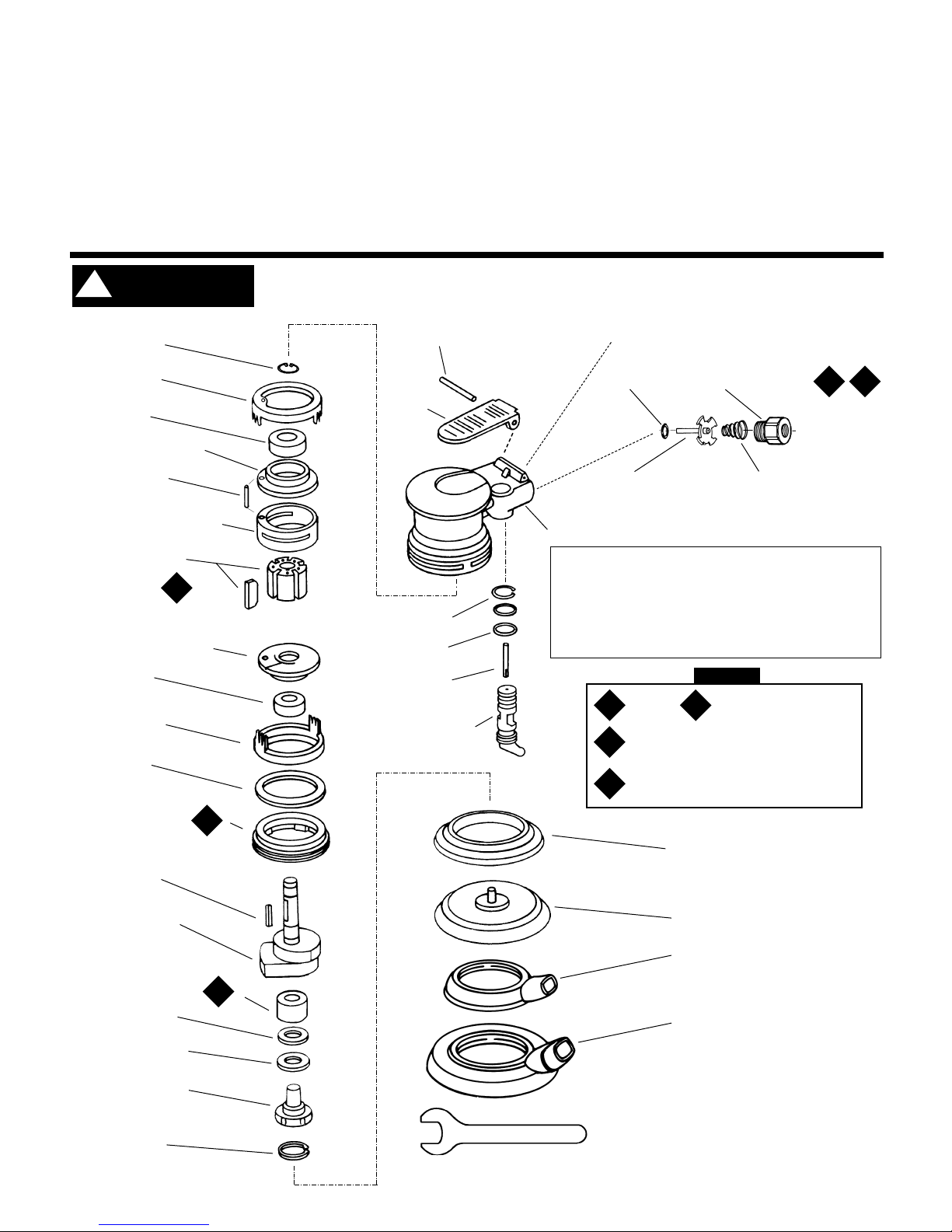
Dynorbital
®
Supreme
Housing
95979 Pin
57063 Lever
01025 O-Ring (2)
01477 Valve Stem
Motor Shaft Balancer
57060 — 3-1/2"
57061 — 5"
57062 — 6"
Sanding Pads - see page 7.
Vacuum Overskirts
57084 — 3-1/2" Models
57086 — 5" Models
57087 — 6" Models
57054 Rear Ring
01206 Bearing
57056 Rear Bearing Plate
95971 Line-up Pin
57058 Cylinder Assembly
(Includes 95971 Line-up Pin)
57113Blade (5) and
Rotor set
57057 Front Bearing Plate
57088 Bearing
57059 Lock Ring Seal
95630 Snap Ring
56047 Rotor Key
57055 Front Ring
95973 Washer
56052 Balancer Bearing
57069 Balancer Shaft
56053 Bearing Seal
95628 Bearing Shield
95626 Snap Ring
01494 Inlet Bushing
01468 Spring
01464 Seal
See page 2 for Machine Exhaust Assemblies.
01472 Tip Valve
57071 - 3-1/2" Non-Vac 57095 - 5" Central-Vac w/overskirt
57072 - 3-1/2" Vac 57080 - 6" Non-Vac
57073 - 3-1/2" Central-Vac 57081 - 6" Vac
57077 - 5" Non-Vac 57082 - 6" Central-Vac
57078 - 5" Vac 57096 - 6" Vac w/overskirt
57079 - 5" Central-Vac 57097 - 6" Central-Vac w/overskirt
57094 - 5" Vac w/overskirt
57064 Speed Regulator
or
57053 Recessed Speed
Regulator
50679 26mm Wrench
Note: To order replacement parts specify the model and serial number of your machine.
95697 Snap Ring
Lip-Seal Shroud (Non-Vac only)
54458 — 3-1/2" models
56051 — 5" and 6" Models
Vacuum Lip-Seal Shroud
57089 — 5" and 6" Models
T2L
2
O
KEY
L
T
O
Loctite/Hernon: L
2
= Loctite #271
Torque: N•m x 8.85 = In. - lbs.
T
2
= 23 N•m, T3= 28 N•m
G
Oil
Grease
T
3
L
2
!
WARNING
Page 2
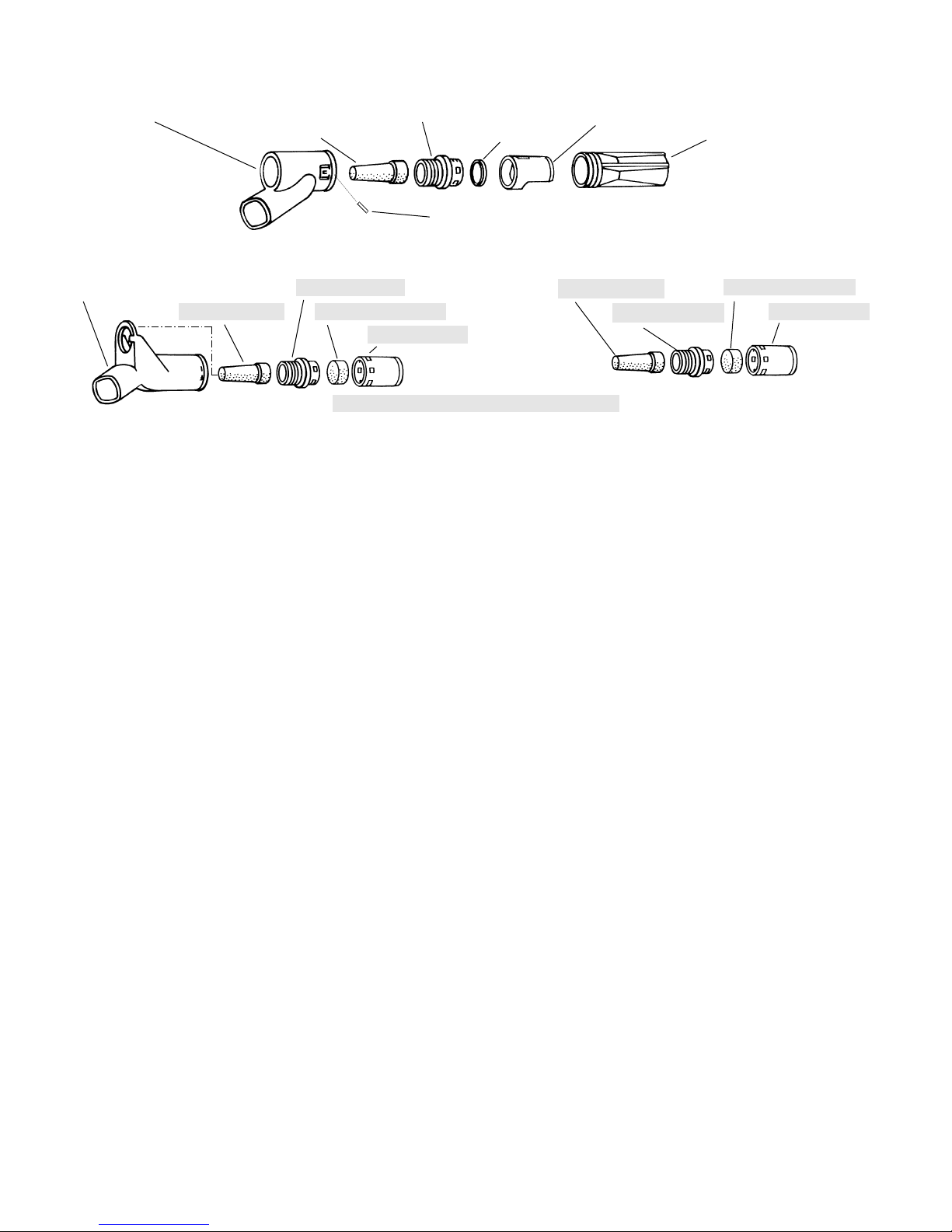
57083 Vacuum Adapter
57065 Cone Muffler
57066 Muffler Body
95526 O-Ring
57068 Vac Nozzle
57067 Vac Tube
57093 Vacuum Adapter
57065 Cone Muffler
57066 Muffler Body
56027 Muffler Insert (3)*
56028 Muffler Cap
57065 Cone Muffler
Shaded parts represent 57112 Muffler assembly.
57066 Muffler Body
56027 Muffler Insert (3)*
56028 Muffler Cap
Machine Exhaust Assemblies
Self Generated Vacuum (Vac-Ready)/Machine Exhaust
For Models: 57001, 57002, 57003, 57016, 57017, 57018, 57021, 57022, 57023, 57027, 57028, 57029, 57032, 57033, 57034
Central Vacuum/Machine Exhaust
For Models: 57004, 57019, 57024, 57030, 57035
Non-Vacuum/Machine Exhaust
For Models: 57000, 57015, 57026
2
96197 Dowel Pin
Vacuum Conversion Instructions
To Disassemble:
1. Disconnect tool from power source. Invert machine and secure in vise, using 57092 Collar (supplied in 57098 Repair Kit) or padded jaws.
2. Remove sanding pad with 50679 (26mm) Open-End Wrench (supplied with sander) and lip-seal shroud from housing.
3. Remove 56028 Muffler Cap and 56027 Muffler Insert (3) from 57066 Muffler Body. Using a 12mm hex wrench (supplied in 57098 Repair Kit), remove
muffler body and 57065 Cone Muffler from housing (not applicable for Self-Generated Vac to Central Vac).
Non-Vac to Self-Generated Vac for Hook-Up to Self-Contained Dust Collection System
1. Attach 57083 Vacuum Adapter to either 57086, 57087 Vacuum Overskirts or 57089 Vacuum Lip-Seal Shroud. Then attach to the housing making sure the
protrusions on the overskirt or shroud are aligned with the notches on the housing.
2. Place 95526 O-Ring on the muffler body between the shoulder and the four (4) protrusions. Using a 12mm hex wrench, attach the muffler body, cone
muffler and O-ring to the housing through the vacuum adapter.
3. Place vacuum nozzle into the vacuum adapter with the slots facing outward making sure that the knob on the nozzle is aligned with the slot in the adapter.
4. Place 57067 Vacuum Tube into the vacuum adapter with the grooves facing inward until the adapter “snaps” onto the tube and the tube cannot be pulled
out. If the tube can be pulled out, rotate it 1/4 turn and place it back into the adapter until it “snaps”.
5. Rotate tube until holes line up. Insert dowel pin in holes until it is centered. Attach sanding pad, attach machine to portable dust collection system.
Non-Vac to Central Vac
1. Attach 57093 Vacuum Adapter to either 57086, 57087 Vacuum Overskirts or 57089 Vacuum Lip-Seal Shroud. Then attach to the housing making sure the
protrusions on the overskirt or shroud are aligned with the notches on the housing.
2. Using a 12mm hex wrench, attach the muffler body and cone muffler to the housing through the central vacuum adapter.
3. Place muffler cap with inserts on muffler body making sure that the protrusions on the body fit in the pockets on the cap.
4. Attach weight-mated vacuum sanding pad with 50679 (26mm) Open-End Wrench. Attach machine to central vacuum system.
Self-Generated Vac to Central Vac
1. Remove 96197 Dowel Pin with an 1/8" drive pin. Remove 57067 Vacuum Tube from 57083 Vacuum Adapter by turning it clockwise while pulling backwards.
2. Using a small flat screwdriver, pry vacuum nozzle until it is loose and then remove it by using two fingers to push and pull it until it hits the “legs” on vacuum
adapter. Place vacuum tube back into vacuum adapter far enough to push the “legs” back then push vacuum nozzle and vacuum tube out the rest of way.
3. Using a 12mm hex wrench (supplied in 57098 Repair Kit), remove the 57066 Muffler Body, 57065 Cone Muffler and 95526 O-Ring from the housing
through the adapter. Remove the O-ring from the muffler body.
4. Remove 57083 Vacuum Adapter and attach 57093 Vacuum Adapter to either 57086, 57087 Vacuum Overskirts or 57089Vacuum Lip-Seal Shroud. Then
attach to the housing making sure that the protrusions on the overskirt or shroud are aligned with the notches on the housing.
5. Using a 12mm hex wrench, attach the muffler body, cone muffler and O-ring to the housing through the central vacuum adapter.
6. Place muffler cap with inserts on muffler body making sure that the protrusions on the body fit in the pockets on the cap. Attach sanding pad.
Central Vac to Self Generated Vac
1. Remove 57093 Central Vacuum Adapter and put the 57083 Vacuum Adapter in its place.
2. Place 95526 “O” Ring on the muffler body between the shoulder and the four (4) protrusions. Using a 12mm hex wrench (supplied in 57098 Repair Kit),
attach the muffler body, cone muffler and O-ring to the housing through the vacuum adapter.
3. Place vacuum nozzle into the vacuum adapter with the slots facing outward making sure that the knob on the nozzle is aligned with the slot in the adapter.
4. Place 57067 Vacuum Tube into the vacuum adapter with the grooves facing inward until the adapter “snaps” onto the tube and the tube cannot be pulled
out. If the tube can be pulled out, rotate it 1/4 turn and place it back into the adapter until it “snaps”.
5. Rotate tube until holes line up. Insert 96197 Dowel Pin in holes until it is centered. Attach machine to portable dust collection system.
Page 3

Important Operating, Maintenance and Safety Instructions
Carefully read all instructions before operating or servicing any Dynabrade® Abrasive Power Tool.
Warning: Hand, wrist and arm injury may result from repetitive work motion and overexposure to vibration.
Important: All Dynabrade air tools must be used with a Filter-Regulator-Lubricator to maintain all warranties.
Operating Instructions:
Warning: Eye, face and body protection must be worn while operating power tools. Failure to do so may result in serious injury or death. Follow safety
procedures posted in workplace.
1. With power source disconnected from tool, securely fasten abrasive/accessory on tool.
2. Install air fitting into inlet bushing of tool. Important: Secure inlet bushing of tool with a wrench before attempting to install the air fitting to avoid damaging
valve body housing.
3. Connect power source to tool. Be careful not to depress throttle lever in the process.
4. Check tool speed with tachometer. If tool is operating at a higher speed than the RPM marked on the tool or operating improperly, the tool should be
serviced to correct the cause before use.
Maintenance Instructions:
1. Check tool speed regularly with a tachometer. If tool is operating at a higher speed than the RPM marked on the tool, the tool should be serviced to correct
the cause before use.
2. Some silencers on air tools may clog with use. Clean and replace as required.
3. All Dynabrade air motors should be lubricated. Dynabrade recommends one drop of air lube per minute for each 10 SCFM (example : if the tool
specification state 40 SCFM, set the drip rate of your filter-lubricator at 4 drops per minute). Dynabrade Air Lube (P/N 95842: 1pt. 473ml.) is recommended.
4. An air line filter-regulator-lubricator must be used with this air tool to maintain all warranties. Dynabrade recommends the following: 11289 Air Line Filter-
Regulator-Lubricator — Provides accurate air pressure regulation, two-stage filtration of water contaminants and micro-mist lubrication of pneumatic
components. Operates 40 CFM @ 100 PSI has 3/8" NPT female ports.
5. Use only genuine Dynabrade replacement parts. To reorder replacement parts, specify the Model #, Serial #, and RPM of your machine.
6. A motor tune-up kit (P/N 96024) is available which includes assorted parts to help maintain motor in peek operating condition.
7. Mineral spirits are recommended when cleaning the tool and parts. Do not clean tool or parts with any solvents or oils containing acids, esters, keytones,
chlorinated hydrocarbons or nitro carbons.
Safety Instructions:
Products offered by Dynabrade should not be converted or otherwise altered from original design without expressed written consent from
Dynabrade, Inc.
• Important: User of tool is responsible for following accepted safety codes such as those published by the American National Standards Institute (ANSI).
• Operate machine for one minute before application to workpiece to determine if machine is working properly and safely before work begins.
• Always disconnect power supply before changing abrasive/accessory or making machine adjustments.
• Inspect abrasives/accessories for damage or defects prior to installation on tools.
• Please refer to Dynabrade’s Warning/Safety Operating Instructions Tag (Reorder No. 95903) for more complete safety information.
Notice
All Dynabrade motors use the highest quality parts and metals available and are machined to exacting tolerances. The failure of quality pneumatic motors can
most often be traced to an unclean air supply or the lack of lubrication. Air pressure easily forces dirt or water contained in the air supply into motor bearings
causing early failure. It often scores the cylinder walls and the rotor blades resulting in limited efficiency and power. Our warranty obligation is contingent upon
proper use of our tools and cannot apply to equipment which has been subjected to misuse such as unclean air, wet air or a lack of lubrication during the use of
this tool.
3
One Year Warranty
Following the reasonable assumption that any inherent defect which might prevail in a product will become apparent to the user within one year from the date
of purchase, all equipment of our manufacture is warranted against defects in workmanship and materials under normal use and service. We shall repair or
replace at our factory, any equipment or part thereof which shall, within one year after delivery to the original purchaser, indicate upon our examination to
have been defective. Our obligation is contingent upon proper use of Dynabrade tools in accordance with factory recommendations, instructions and safety
practices. It shall not apply to equipment which has been subject to misuse, negligence, accident or tampering in any way so as to affect its normal
performance. Normally wearable parts such as bearings, contact wheels, rotor blades, etc., are not covered under this warranty.
Page 4

Motor Assembly/Disassembly Instructions – Dynorbital®Supreme Sander
Important: Manufacturers warranty is void if tool is disassembled before warranty expires.
A complete repair kit, part number 57098, is available which includes special tools for correct disassembly/assembly of tool.
To Disassemble
1. Disconnect tool from power source.
2. Invert machine and secure in vice, using 57092 Collar (supplied in 57098 Repair Kit) or padded jaws.
3. Remove sanding pad with 26 mm open-end wrench (supplied with sander) and shroud or overskirt.
4. Insert 56058 Lock Ring Tool (supplied in 57098 Repair Kit) into corresponding tabs of lock ring and unscrew.
Motor may now be lifted out for service.
Note: To get it started try using 26 mm wrench for leverage or rock the motor back and forth to loosen up the rings.
5. Remove lock ring, washer, front ring and rear ring from motor. Upper motor may now be disassembled. Remove
95626 Snap Ring
6. Remove the rear plate and the cylinder assembly by securing the cylinder in a bearing separator gripped on the
cylinder exhaust and extra pocket area. Push the motor shaft balancer through the bearing.
7. Remove the rotor, vanes and rotor key from the motor shaft balancer. Remove the front plate using a small
(#2) arbor press. Support the edges of the front plate while pressing on the small end of the motor shaft balancer.
8. a.) If, during step 7, the front plate and 57088 Bearing remain together, press 57088 Bearing out of the front plate
using 57091 Press Tool (supplied in 57098 Repair Kit) as shown in Drawing 1.
b.) If, during step 7, the front plate and 57088 Bearing remains on the motor shaft balancer, it can be removed with
a bearing separator.
9. Remove 01206 Bearing from the rear plate by using a bearing press tool.
10.Disassemble the balancer assembly as follows:
a.) Place motor shaft assembly into a soft jaw vise. Using a thin screwdriver, pick out the end of 95630 Snap Ring
and peel out. This will loosen the balancer assembly.
b.) Screw the threaded portion of the 56056 Bearing Puller (supplied in 57098 Repair Kit) into the 57069 Balancer
Shaft and heat the outside of the motor shaft balancer to approximately 200° F (approximately 10 seconds with a
propane torch). Now, using the slider weight, pull the assembly out.
c.) Press off 56052 Bearing with a bearing separator and remove bearing seal and bearing shield.
11. If during step 10, the 56052 Bearing remains in the motor shaft balancer, it can be removed by the heating the
shaft balancer again and using either an inside bearing puller or a blind hole bearing puller.
To Reassemble:
Important: Be certain parts are clean and in good repair before reassembling.
1. Assemble the balancer assembly as follows:
a.) Install 95630 Snap Ring onto balancer shaft. Install 95628 Shield with convex face toward hex of balancer shaft.
b.) Install 56053 Seal. Note:Be certain seal is pressed completely over shaft step.
c.) Apply 1 drop of #271 Loctite® (or equivalent) and spread over several places around the inside diameter of the
56052 Bearing and the outside diameter of the 57069 Balancer Shaft.
d.) Press fit 56052 Bearing with seal side toward hex of balancer shaft up to shaft step as shown in Drawing 2.
This must be a firm press fit for proper retention of bearing.
2. Place the motor shaft balancer in a soft jaw vise with large end-up.
3. Apply 1 drop of #271 Loctite® (or equivalent) and spread over several places around the outside diameter of the
56052 Bearing and slide balancer assembly into the motor shaft balancer until 56052 Bearing is firmly seated at
bottom. Squeeze 95630 Snap Ring into groove in motor shaft balancer to complete the assembly. Remove from vise.
4. Press 57088 Bearing onto the motor shaft balancer down to the shoulder as shown in Drawing 3.
5. Press 57057 Front Bearing Plate onto 57088 Bearing as shown in Drawing 4 and check for smooth rotation.
6. Place the 57090 Rotor and 56047 Rotor Key on the motor shaft balancer. Place the 56073 Vanes into the rotor slots.
Note: Vanes should be lightly lubricated with Dynabrade Air Lube P/N 95842 (or equivalent) before installation.
7. Place 57058 Cylinder Assembly over rotor. The “short” line-up pin goes toward the Front Plate.
8. Place 57056 Rear Bearing Plate (with 01206 Rear Bearing pressed into place) over shaft and “long” end of line-up
pin and press fit in place as shown in Drawing 5.
9. Place 95626 Snap Ring in groove.
10.Place 57054 Rear Ring over the rear plate and line-up pin. Turn the motor over and place 57055 Front Ring over the
front plate making sure that the “legs and fingers” on the front and rear rings line-up. Also the small cut-outs on both
rings should line-up with the square holes in the cylinder/endplate assembly.
11. Place 95973 Washer and 57059 Lock Ring onto the front ring with 1 drop of pneumatic tool oil spread between the
washer and lock ring.
12.Secure motor housing in vise, using 57092 Collar or padded jaws. Spread 2-3 drops of pneumatic tool oil around the
housing bore for ease of insertion of motor assembly. Slide motor assembly into secured housing.
Note: Be certain line-up pin enters the pocket in the bottom of the housing and the “legs” of the rings stay in line.
13.Tighten lock ring with 56058 Lock Ring Tool to 28 N•m/250 in. - lbs. Attach shroud or overskirt and weight-mated sanding pad.
Tool assembly is complete. Please allow 30 minutes for adhesives to cure before operating tool.
(continued on next page)
4
Drawing 1
57091
Bearing Press Tool
57088 Bearing
57057
Front Bearing Plate
Support
57091
Bearing Press Tool
Balancer Shaft Assembly
56052 Bearing
Shaft Step
Bearing Seal and
Bearing Shield
Drawing 2
Balancer Shaft Assembly
Motor Shaft Balancer
57088 Bearing
57091
Bearing Press Tool
Drawing 3
Page 5

5
Valve and Speed Regulator Assemblies:
1. Secure housing in vice using 57092 Collar or padded jaws.
2. Remove inlet bushing, 01468 Spring, hinge valve and 01464 Seal from housing.
3. Remove 95697 Snap Ring. Press the spread regulator and valve stem out of the housing. Remove the 01025 O-Rings (2).
4. Place new 01025 O-Rings (2) on the speed regulator and place inhousing with valve stem. Install new 95967 Snap Ring.
5. Place new 01464 Seal in housing, . Using tweezers or needle nose pliers, place the tip valve into housing so that the pin goes through the valve stem
hole. Place new 01468 Spring into housing so small end is towards tip valve.
6. Spread 1 drop of #271 Loctite® (or equivalent) around the threads of the first inlet bushing and tighten into housing to 23 N•m/200 in. - lbs.
Note: Motor should operate at between 9,500 and 10,000 RPM at 6.2 bar (90 PSI). RPM should be checked with a reed tachometer. Before operating, we
recommend that 2-3 drops of Dynabrade Air Lube P/N 95842 (or equivalent) be placed directly into the air inlet with throttle lever depressed. Operate the
machine for approximately 30 seconds before application to workpiece to determine if machine is working properly and safely and to allow lubricating
oils to properly dispense through machine.
Loctite®is a registered trademark of the Loctite Corp.
Disc Pad Change:
1.
Insert 50679 Wrench on flats of 57069 Balancer Shaft and twist off sanding pad by hand.
2.
With wrench still in place, hand tighten new pad on tool.
3.
No need to remove shroud or overskirt.
Required Weight of Pads:
3-1/2" Models –– Use pad weighing 80g.
5" Models –– Use pad weighing 100g.
6" Models –– Use pad weighing 130g.
57091
Bearing Press Tool
Balancer Shaft Assembly
Motor Shaft Balancer
57088 Bearing
57057
Front Bearing Plate
Drawing 4
57091
Bearing Press Tool
Balancer Shaft Assembly
Motor Shaft Balancer
57057 Front Bearing Plate
(with 57088 Bearing)
57056 Rear Bearing Plate
(with 01206 Bearing)
57058 Cylinder
Assembly.
(w/Rotor and Vanes)
Line-Up Pin
Drawing 5
Motor Assembly/Disassembly Instructions – Dynorbital®Supreme Sander
Optional Accessories
96024 Motor Tune-Up Kit:
Includes assorted parts to help
maintain motor in tip-top shape.
57098 Motor Repair Kit:
Includes special tools for proper disassembly/assembly of
the Dynorbital® Supreme.
Page 6

57000 3-1/2" (89) 6" (152) 3-3/4" (95) 2.1 lbs. (1.0 kg) 5/16"-24 female 73 dB(A) 1/4" NPT 1/4" 90 PSI 10,000
57001 3-1/2" (89) 8-1/4" (209) 3-3/4" (95) 2.1 lbs. (1.0 kg) 5/16"-24 female 73 dB(A) 1/4" NPT 1/4" 90 PSI 10,000
57004 3-1/2" (89) 7" (177) 3-3/4" (95) 2.1 lbs. (1.0 kg) 5/16"-24 female 73 dB(A) 1/4" NPT 1/4" 90 PSI 10,000
57015 5" (127) 6-1/2" (165) 3-5/8" (92) 2.1 lbs. (1.0 kg) 5/16"-24 female 73 dB(A) 1/4" NPT 1/4" 90 PSI 10,000
57018 5" (127) 8-1/2" (216) 3-5/8" (92) 2.1 lbs. (1.0 kg) 5/16"-24 female 73 dB(A) 1/4" NPT 1/4" 90 PSI 10,000
57019 5" (127) 7-1/4" (184) 3-5/8" (92) 2.1 lbs. (1.0 kg) 5/16"-24 female 73 dB(A) 1/4" NPT 1/4" 90 PSI 10,000
57023 5" (127) 8-3/4" (222) 3-5/8" (92) 2.1 lbs. (1.0 kg) 5/16"-24 female 73 dB(A) 1/4" NPT 1/4" 90 PSI 10,000
57024 5" (127) 7-1/2" (184) 3-5/8" (92) 2.1 lbs. (1.0 kg) 5/16"-24 female 73 dB(A) 1/4" NPT 1/4" 90 PSI 10,000
57026 6" (152) 8-3/4" (222) 3-1/2" (89) 2.1 lbs. (1.0 kg) 5/16"-24 female 73 dB(A) 1/4" NPT 1/4" 90 PSI 10,000
57029 6" (152) 7" (177) 3-1/2" (89) 2.1 lbs. (1.0 kg) 5/16"-24 female 73 dB(A) 1/4" NPT 1/4" 90 PSI 10,000
57030 6" (152) 7-3/4" (196) 3-1/2" (89) 2.1 lbs. (1.0 kg) 5/16"-24 female 73 dB(A) 1/4" NPT 1/4" 90 PSI 10,000
57034 6" (152) 9-1/4" (235) 3-1/2" (89) 2.4 lbs. (1.1 kg) 5/16"-24 female 73 dB(A) 1/4" NPT 1/4" 90 PSI 10,000
57035 6" (152) 8" (203) 3-1/2" (89) 2.4 lbs. (1.1 kg) 5/16"-24 female 73 dB(A) 1/4" NPT 1/4" 90 PSI 10,000
Model Pad Dia. Length Height Machine Spindle Noise Air Inlet Hose Air
Number Inch (mm) Inch (mm) Inch (mm) Weight Thread Level Thread Size Pressure RPM
6
Self-Contained Dust Collection Systems
Easily attach to Dynorbital® Supreme Random Orbital Sander – Self-Generated Vac-Ready Models.
Machine Specifications
50694 Mini-Reusable Cloth Bag
• Mounts directly to any Vac-Ready
tool or to any exhaust hose.
• Measures 11" long x 3" wide.
End opens up - no need to remove
bag from tool when emptying.
50683 Reusable Cloth Bag
• Hook ‘n loop end for easy emptying.
• Measures 14-1/2" L x 7-1/2" W.
• Connects to vacuum hose.
56304 Reusable Cloth Bag w/Zipper
• Has zipper-lock end.
• Measures 14-1/2" L x 7-1/2" W.
• Connects to vacuum hose.
95986 Hose Cover
(5' long cloth cover)
• Covers air line and exhaust/vacuum
hoses (not included).
• Eliminates damage from hoses
dragging on the workpiece.
54290 “Bag-in-Box” System
• 95361 Air Line 5' long.
• 50682 Flex-Hose 1" dia. x 6' long.
• 95362 Rubber Connectors (5, attach
air line to vacuum hose).
• 95575 Durable Box Receptacle (to
house bag and store tool).
• Sample paper bag included.
Paper bag reorder:
50692 (400/case) or
50693 (24 per package.)
50617 & 56303 – 6' Long Flex-Hose
• Both systems include 6' long 50682
Flex-Hose.
• Shown with optional 95361 Air Line
(1/4" diameter).
50617: Has 50683 Standard Reusable
Cloth Bag with hook ’n loop
end for easy emptying.
56303: Has 56304 Zipper-Lock Bag.
54284 Mini-Flex-Hose System
• 95580 Air Line 1" dia. x 28" long.
• 50638 Flex-Hose 1" dia. x 18" long.
• 50694 Mini-Reusable Cloth Bag.
• 95362 Rubber Connectors (3) which
connect air line to exhaust hose.
Page 7

7
Random Orbital Sanding Pads
Perfectly balanced and weight-mated to Dynorbital® Supreme Random Orbital Sander.
Coated Abrasive Discs
Pad 3-1/2" 5" 6"
Description Dual Purpose Non-Vac Vac Non-Vac Vac
3/8" Thick, Soft Density — 56102 56100 56103 56101
3/8" Thick, Medium Density — 56106 56104 56107 56105
5/8" Thick, Soft Density 56097 56185 56186 56187 56188
5/8" Thick, Medium Density 56098 56175 56176 56177 56178
Premium Urethane Pad - Vinyl Face for PSA-Type Discs
Pad 3-1/2" 5" 6"
Description Dual Purpose Non-Vac Vac Non-Vac Vac
3/8" Thick, Soft Density — 56157 56155 56158 56156
3/8" Thick, Medium Density — 54325 54326 54327 54328
5/8" Thick, Soft Density 54311 56195 56196 56197 56198
5/8" Thick, Medium Density 54313 56180 56181 56182 56183
Premium Urethane Pad - Hook Face Short Nap Pads for Scrim-Back Discs
Pad 3-1/2" 5" 6"
Description Dual Purpose Non-Vac Vac Non-Vac Vac
1/2" Thick, "Diamond Pattern Face" — 50630 50631 50632 56101
1/2" Thick, "Post Pattern Face" — — 50695 — 50696
Rubber Pad, Medium Density - Vinyl Face Pads for PSA-Type Discs
Pad 3-1/2" 5" 6"
Description Dual Purpose Non-Vac Vac Non-Vac Vac
1/2" Thick, Medium Density 54314 50605 50607 50606 50610
Rubber, Medium Density - Hook Face Long Nap Pads for Non-Woven Nylon Discs
• Premium urethane pads, available in soft or medium density, resist heat build-up.
• New 5/8" thick pads, ideal for sanding of intricate contours.
•Unique vinyl surface pads provide excellent disc adhesion, allowing for quick removal of used discs.
• Special rubber/vinyl face pads for PSA discs.
• "Post Pattern" design for enhanced vacuum pick-up.
•Unique vinyl surface pads provide excellent disc adhesion, allowing for quick removal of used discs.
• No need to align vacuum holes, saves time on disc changes.
• Hook face "short nap" pads for reattachable discs.
• Hook face "long nap" pads for Abrasive Impregnated Non-Woven Nylon Discs.
Disc
Type
Silicon Carbide Discs / PSA Mounted
Premium Aluminum Oxide Discs / PSA Mounted
Abrasive Grit
80 100 120 150 180 220
No Holes 93051 93052 93053 93054 93055 93056
5-Hole Pattern 93060 93061 93062 93063 93064 93065
No Holes 93069 93070 93071 93072 93073 93074
6-Hole Pattern 93077 93078 93079 93080 93081 93082
Abrasive Grit
80 100 120 150 180 220 320
*No Holes 92090 – 92092 – 92094 92095 92097
No Holes 93101 93102 93103 93104 93105 93106 –
5-Hole Pattern 93109 93110 93111 93112 93113 93114 –
No Holes 93200 93201 93202 93203 93204 93205 –
6-Hole Pattern 93215 93216 93217 93218 93219 93220 –
Note: Other grits available upon request.
*Used on either vacuum or non-vacuum 3-1/2" sander.
All Discs: 120 Grit and Coarser – 125/Roll; 10 Rolls = Unit.
150 Grit and Finer – 175/Roll; 6 Rolls = Unit. Complete rolls only.
6" Diameter
Disc
Type
Note: Other grits available upon request.
All Discs: 120 Grit and Coarser – 125/Roll; 8 Rolls = Unit.
150 Grit & Finer – 250/Roll; 4 Rolls = Unit. Complete rolls only.
5" Diameter
3-1/2" Diameter
5" Diameter
6" Diameter
• 3-1/2", 5" and 6" diameter disc pads have 5/16"-24 male threaded stud.
• The 3-1/2" diameter discs, without holes, can be used on vacuum and non-vacuum 3-1/2" Dynorbital® Supreme Sanders.
Page 8

DYNABRADE
®
Toll Free (U.S.A.) 1-800-828-7333
Toll Free (Can.) 1-800-344-1488
DYNABRADE, INC., 8989 Sheridan Drive • Clarence, NY 14031-1490 • Phone: (716) 631-0100 • Fax: 716-631-2073 • International Fax: 716-631-2524
DYNABRADE EUROPE S.àr.l., Zone Artisanale • L-5485 Wormeldange—Haut, Luxembourg • Telephone: 352 76 84 94 • Fax: 352 76 84 95
©DYNABRADE, INC., 1997 PRINTED IN USA
Visit our new Web Site via Industry.Net MROP On-Line: http://www.dynabrade.industry.net E-Mail: DynaTalk@aol.com
 Loading...