

Page 1
SAFETY INSTRUCTIONS
Carefully Read all instructions before operating or servicing any Dynabrade
®
Abrasive Power Tool.
Products offered by Dynabrade are not to be modified, converted or otherwise altered from the original design .
Tool Intent: 3" Dynabuffer are specifically designed for clear coat repair. The tool is designed to remove scratches left over from sanding
imperfections in clear coat finishes.
Do not use tool for anything other than its intended applications.
This power tool is not intended for use in potentially explosive atmospheres and is not insulated against contact with electrical power.
Training: Proper care, maintenance, and storage of your tool will maximize performance.
• Employer's Responsibility – Provide 3" Dynabuffer operators with safety instructions and training for safe use of tools and accessories.
Accessory Selection:
• Accessory RPM (speed) rating MUST be approved for AT LEAST the tool RPM rating.
• Before mounting an accessory, visually inspect for defects. Do not use defective accessories.
• Use only 3" weight-mated Dynabrade back-up pads. Attach 3" foam buffing pads. Do Not use grinding wheels or cut-off wheels.
• Follow tool specifications before choosing size and type of accessory.
• Only use recommended fittings and air line sizes. Air supply hoses and air hose assemblies must have a minimum working pressure rating of 150 PSIG
(10 Bars, g) or 150 percent of the maximum pressure produced in the system, whichever is higher. (See tool Machine Specifications table.)
Parts Page Reorder No. PD10•08
Effective March, 2010
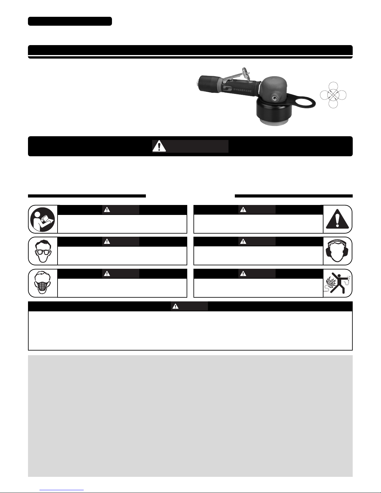
3" Dynabuffer
Tool Manual – Safety, Operation and Maintenance
Model:
55126 – 12,000 RPM
SAVE THIS DOCUMENT, EDUCATE ALL PERSONNEL
14mm Random
Orbit Motion
SAFETY LEGEND
WARNING
WARNING
Read and understand tool manual before
work starts to reduce risk of injury to
operator, visitors, and tool.
WARNING
Eye protection must be worn at all times,
eye protection to conform to ANSI Z87.1.
WARNING
Respiratory protection to be used when exposed to
contaminants that exceed the applicable threshold
limit values required by law.
WARNING
Practice safety requirements. Work alert,
have proper attire, and do not operate tools under
the influence of alcohol or drugs.
WARNING
Ear protection to be worn when exposure to sound,
exceeds the limits of applicable Federal, State or
local statues, ordinances and/or regulations.
WARNING
Air line hazard, pressurized supply lines and flexible
hoses can cause serious injury. Do not use damaged,
frayed or deteriorated air hoses and fittings.
Read and understand this tool manual before operating your air tool. Follow all safety rules for the protection of operating personnel
as well as adjacent areas. Always operate, inspect and maintain this tool in accordance with the American National Standards
Institute (ANSI) Safety Code for Portable Air Tools – B186.1. For additional safety information, refer to Safety Requirements for the
Use, Care and Protection of Abrasive Wheels – ANSI B7.1, Code of Federal Regulation – CFR 29 Part 1910, European Committee for
Standards (EN) Hand Held Non-Electric Power Tools – Safety Requirements and applicable State and Local Regulations.
WARNING
Some dust created by sanding, grinding, drilling, and other construction activities contain chemicals known to cause cancer, birth
defects or other reproductive harm. Some examples of these chemicals are:
• Lead from lead-based paints
• Crystalline silica from bricks and cement and other masonry products
• Arsenic and chromium from chemically treated lumber
Your risk from these exposures varies, depending on how often you do this type of work. To reduce your exposure to these chemicals: work in a well ventilated area,
and work with approved safety equipment, such as those dust masks that are specially designed to filter out microscopic particles.
FIND THE MOST CURRENT OFFERING OF SUPPORT DOCUMENTS AND ACCESSORIES @ WWW.DYNABRADE.COM
For Serial No. 13F2196A and Higher
Page 2

To Tool Station
Closed Loop Pipe System
(Sloped in the direction of air flow)
Ball
Valve
Ball
Valve
Filter
Regulator
Lubricator
Air Flow
Drain
Valve
Drain
Valve
Air Tool
Air Compressor
and Receiver
Drain Valve
Air Hose
Air Flow
Refrigerated
Air Dryer
2
Filter
Regulator
Lubricator
90 PSIG
(6.2 Bar)
OPERATING INSTRUCTIONS
Warning: Always wear eye protection. Operator of tool is responsible for following: accepted eye, face, respiratory, hearing and body protection.
Caution: Hand, wrist and arm injury may result from repetitive work, motion and overexposure to vibration. Operate tool ONLY under load.
• Keep hand and clothing away from working end of the air tool.
• Working end of the air tool has potential hazard of cutting.
Operation: Be sure that any loose clothing, hair and all jewelry is properly restrained.
• Secure inlet bushing on air tool with a wrench before attempting to install the air fitting to avoid damaging housing assembly.
• BEFORE MOUNTING AN ACCESSORY, after all tool repairs and whenever a 3" Dynabuffer is issued for use, check tool RPM
(speed) with tachometer, see Routine Preventative Maintenance for procedure (pg. 3).
Caution: This tool is not to be run at free speed. The tool is specifically designed to be low in vibration under load. Running the tool at free speed may
cause the buffing pad to become dislodged from the back-up pad.
Caution: Tool RPM must never exceed accessory RPM rating. Check accessory manufacturer for details on maximum operating speed or special
mounting instructions.
• With power source connected at the air tool relieve hose of air pressure and disconnect tool from air supply when changing recommended accessories.
• Connect air tool to power source. Be careful NOT to depress throttle lever in the process.
• Do not expose air tool to inlet pressure above 90 PSIG or (6.2 Bars).
Caution: After installing the accessory, before testing or use and/or after assembling tool, the 3" Dynabuffer must be started at a
reduced speed to check for good balance. Gradually increase tool speed. DO NOT USE if tool vibration is excessive. Correct cause, and retest to
insure safe operation.
• It is imperative that the correct weight mated back-up pad be used with the tool to avoid excessive vibration. The tool is designed to use a Dynabrade P/N
56142 Pad; this pad has a mass of 30 grams.
• Ensure that self-fixing foam buffing pads are mounted concentrically to back-up pad.
• Precondition new foam buffing pads with buffing compound before use.
• Apply dab of buffing compound to sand scratch on work surface.
• Apply approximately a 6 pound load on the pad before throttling the tool on. Adjust the force on the pad as required to feel the “sweet spot” (low
vibration). Buffing for approximately 5 seconds with the pad flat on the work surface should remove the sand scratches of the initial process. Release the
throttle lever and then remove the tool from the work piece.
• Release the throttle lever in case of an interruption of the energy supply.
• Make sure that work area is uncluttered, and visitors are at a safe range from the tools and debris.
• Potentially explosive atmospheres can be caused by dust and fumes resulting from buffing. Always use dust extraction or suppression systems which are
suitable for the material being processed.
• Proceed with caution in unfamiliar surroundings. Hidden hazards may exist, such as electricity or other utility lines.
• Air tools are not intended for use in explosive atmospheres and are not insulated for contact with electric power sources.
• Work may generate hazardous dust.
• Do not apply excessive force on tool or apply “rough” treatment to it.
• Always work with a firm footing, posture and proper lighting.
• This tool is front exhaust. Exhaust may contain lubricants, vane material, bearing grease, and other materials flushed thru the tool.
Report to your supervisor any condition of the tool, accessories, or operation you consider unsafe.
Air System
1 DROP/MIN.
20 SCFM
LUBRICATOR SETTING
•
Dynabrade Air Power Tools are designed to
operate at 90 PSIG (6.2 Bar/620 kPa) maximum
air pressure at the tool inlet, when the tool is
running. Use recommended regulator to control
air pressure.
•
Ideally the air supply should be free from moisture.
To facilitate removing moisture from the air supply,
the installation of a refrigerated air dryer after the
compressor and the use of drain valves at each
station is recommended.
➤
➤
➤
➤
➤
➤
90 PSIG MAX
(6.2 Bar)
Page 3

Maintenance Instructions
Important: To keep tool safe a preventative maintenance program is recommended whenever portable power tools are used. The program should include
inspection of air supply lines, air line pressure, proper lubrication and repair of tools. Refer to ANSI B186.1 for additional maintenance information.
•
Use only genuine Dynabrade replacement parts to insure quality. To order replacement parts, specify Model#, Serial# and RPM of your air tool.
•
It is strongly recommended that all Dynabrade rotary vane air tools be used with a Filter-Regulator-Lubricator to minimize the possibility of misuse due
to unclean air, wet air or insufficient lubrication. Dynabrade recommends the following: 10681 Air Filter-Regulator-Lubricator (FRL) – Provides accurate
air pressure regulation and two stage filtration of water contaminates.
•
If Dynabrade Air Lube is not compatible with paint system it may be substituted with a compatible air tool lubricant with water absorbing properties to
prevent internal components from rusting.
•
Dynabrade recommends one drop of air lube per minute for each 20 SCFM (example: if the tool specification states 40 SCFM, set the drip rate on the
filter-lubricator to 2 drops per minute). Dynabrade Air Lube (P/N 95842: 1 pt 473 ml) is recommended.
Routine Preventative Maintenance:
•
Check tool speed regularly with a tachometer. Tool must be tested with the flow control assembly completely in the full flow position. A Magnetic
Tachometer such as Dynabrade P/N 96368 is the simplest way to perform this operation. To properly check tool speed the tool should be tested under
load. Checking under load requires additional test equipment but assures the proper operation of the tool. All speed testing must be done with 90 psig of
air at the inlet bushing, a Pressure Gage such as Dynabrade P/N 94315 is required. The under load condition can be checked by outfitting the tool with
the proper back-up pad, foam buffing pad and buffing compound. Apparatus is also required to monitor the load applied to the work surface. Dynabrade
offers a Load Cell P/N 80025 that allows the tool to be tested on a bench. First zero out the scale by adjusting the knob on the side of the load cell to
read zero when the tool, back-up pad, and foam buffing pad are resting on the wear plate of the load cell while connected to the air line. Apply a 6
pound load to the load cell and using the digital tachometer check the operating speed of the tool. The tool should be running 7,500 RPM minimum. If
the tool is running outside this range it should be serviced to correct the cause before use.
•
Tool is equipped with a flow control assembly to allow adjustability. Adjustments are strongly recommended to be done during maintenance of the tool
and not at the workstation. Adjustment is accomplished by rotating the 55167 Cap so that the hole aligns with the 5/32" (4 mm) hex in the 55169 Flow
Control. A 5/32" or 4 mm hex wrench is inserted through the hole in the cap and into the hex in the flow control; rotating the wrench either clockwise or
counterclockwise will adjust the speed. The full speed range is accomplished by a 180° twist of the wrench; further rotation of the wrench will simply
repeat the cycle. Once the optimal speed setting is set rotate the 55167 Cap roughly 180° to reduce adjustment access.
•
Using the tool over time may clog 55158 Muffler Insert, this may hamper performance and require replacement.
•
Mineral spirits are recommended when cleaning the tool and parts. Do not clean tool or parts with any solvents or oils containing acids, esters,
ketones, chlorinated hydrocarbons or nitro carbons.
•
DO NOT clean or maintain tools with chemicals that have a low flash point (example: WD-40
®
).
•
A Motor Tune-Up Kit (P/N 96542) is available which includes high wear and medium wear motor parts.
•
Air tool labels must be kept legible at all times, if not, reorder label(s) and replace. User is responsible for maintaining specification information i.e.:
Model #, S/N, and RPM. (See Assembly Breakdown)
•
Blow air supply hose out prior to initial use.
•
Visually inspect air hoses and fittings for frays, visible damage and signs of deterioration. Replace damaged or worn components.
•
Refer to Dynabrade's Warning/Safety Operating Instructions Tag (Reorder No. 95903) for safety information.
After maintenance is performed on tool, add a few drops of Dynabrade Air Lube (P/N 95842) to the air line and start the tool a few times to lubricate air motor.
Check for excessive tool vibration.
Handling and Storage:
•
DO NOT rest tool on pad.
•
Use of tool hanger is recommended.
•
Protect tool inlet from debris (see Notice below).
•
DO NOT carry tool by air hose, or near the tool throttle lever.
•
Protect abrasive accessories from exposure to water, solvents,
high humidity, freezing temperature and extreme temperature changes.
•
Store accessories in protective racks or compartments to prevent damage.
Notice
All Dynabrade motors use the highest quality parts and materials available and are machined to exacting tolerances. The failure of quality pneumatic motors
can most often be traced to an unclean air supply or the lack of lubrication. Air pressure easily forces dirt or water contained in the air supply into motor
bearings causing early failure. It often scores the cylinder walls and the rotor blades resulting in limited efficiency and power. Our warranty obligation is
contingent upon proper use of our tools and cannot apply to equipment which has been subjected to misuse such as unclean air, wet air or a lack of
lubrication during the use of this tool.
Machine Specifications
3
Model Motor Motor Sound Maximum Air Flow Air Pressure Spindle Weight Length Height
Number hp (W) RPM Level SCFM (LPM) PSIG (Bars) Thread Pound (kg) Inch (mm) Inch (mm)
55126 .5 (373) 12,000 79 dB(A) 37 (1048) 90 (6.2) 5/16"-24 female 2.7 (1.2) 9-1/2 (242) 4-1/8 (105)
Additional Specifications: Air Inlet Thread 1/4" NPT • Hose I.D. Size 3/8" (10mm) • Tool Vibration Data (Per ISO 8662.8) 2.0
M
/
S
2
Sound Level is the pressure measurement according to the method outlined in ISO regulation ISO-15744
Page 4

1 56142 3" Pad
2 57069 Balancer Shaft
3 95630 Snap Ring
4 59084 V-Seal
5 56052 Bearing
6 55153 Shaft Balancer
7 54673 Key
8 55154 Lock Ring
9 55155 Lock Ring Spacer
10 02695 Bearing
11 55152 Front Bearing Plate
12 54671 Rotor
13 54674 Vane (5/Pkg.)
14 55151 Cylinder Assembly
(Inclds. 95865 Pin)
15 95865 Pin
16 54679 Rear Bearing Plate
17 01206 Bearing
18 95626 Retaining Ring
19 97101 Screw (4)
20 55157 Inner Shroud
21 55161 O-Ring (2)
22 55158 Muffler Insert
23 55156 Outer Shroud
24 97166 Hangplate
25 55160 Housing
26 51360 Housing Overmold
27 01547 Collar
28 95523 O-Ring
29 45267 Insert
30 45277 Filter Cage
31 45278 Filter
36 97060 Pin
37 97045 Plunger
38 45257 Throttle Bushing
39 01464 Seal (2)
40 58365 Tip Valve
41 01468 Spring
42 95438 O-Ring
43 55166 Muffler Base
44 55167 Muffler Cap
45 95529 O-Ring
46 95558 Retaining Ring
47 01024 O-Ring (2)
48 55169 Flow Control
49 55168 Inlet Adapter
50 55170 Flow Control Assembly
Index Key
No. Part # Description
Adhesive: A2= Loctite #271
A
8
= Loctite #567
Torque: N•m x 8.85 = In. - lbs.
Oil: O
1
= Air Lube
O
A
T
KEY
4
10
9
6
4
3
1
11
18
17
19
20
21
22
23
21
24
25
26
27
28
29 30 31
32
42
43
48
44
50
49
33
34
41
39
40
37
38
3635
12
14
16
15
7
A
2
A
2
O
1
A
8
A
8
A
8
28 N•m
T
A
8
45 N•m
T
O
1
28 N•m
T
15-20 N•m
T
3" Dynabuffer
Complete Assembly
47
45
46
A
8
2
5
8
50679 – 26mm open-end
13
Always follow adhesive manufacturers
cleaning and priming recommendations.
LEFT HAND
THREADS
LEFT HAND
THREADS
Model:
55126
32 45309 Throttle Body Housing
33 96077 O-Ring
34 45206 Housing Sleeve
35 45263 Throttle Lever
Assembly
Page 5

Motor Assembly/Disassembly Instructions – 3" Dynabuffer
IMPORTANT: The Dynabrade Pneumatic Power Tool Lifetime Warranty Policy does NOT cover normally wearable parts and products. Before servicing this
tool please contact Dynabrade Inc. or a Dynabrade Subsidiary for information regarding the Dynabrade Pneumatic Power Tool Lifetime Warranty Policy. The
special repair tooling referred to in these instructions can be ordered from Dynabrade. (See Page 8)
Disconnect tool from the air supply before servicing.
Motor Disassembly:
1. Use the 59293 Offset Wrench (26 mm) to remove the back-up pad.
2. Install the 95492 Screws (part of 96519 Tool Repair Kit) into the two handle bosses in the 55160 Housing.
3. With the shaft balancer (counterbalance) facing up, position 95492 Screws between the vise jaws and secure the 55126 3" Dynabuffer in the vise.
NOTICE: Do not over tighten the vise.
4. Use the 95050 Hex Key (5/64") to remove the four 97101 Screws from the 55157 Inner Shroud.
5. Use the 56058 Lock Ring Wrench to loosen the 55154 Lock Ring. Turn counterclockwise.
6. Loosen the vise and pull the motor assembly out of the 55160 Housing. Use the 96343 Retaining Ring Pliers to remove the 95626 Retaining Ring.
7. Fasten the 96346 Bearing Separator between the 54679 Rear Bearing Plate and the 55151 Cylinder Assembly.
8. With the bearing separator secured to the motor assembly, place the separator on the table of the 96232 Arbor Press (#2) with the counterbalance pointing down.
9. Use a 5/16" diameter flat end drive punch as a press tool and push the 55153 Shaft Balancer out of the 01206 Bearing.
10. Remove the rotor, vanes, and the 54673 Key from the shaft balancer.
11. Remove the 55152 Front Bearing Plate from the 02695 Bearing.
12. Fasten the bearing separator between the counterbalance and the 02695 Bearing. Use the arbor press to remove the bearing.
13. Secure the counterbalance of the 55153 Shaft Balancer in a vise with aluminum or bronze jaws so that the 26 mm hex end of the 57069 Balancer Shaft is
accessible and facing up.
14. Use a small thin screwdriver to pick the notched end of the 95630 Snap Ring out of the shaft balancer. Work the screwdriver under and around the 95630 Snap Ring
to remove it.
15. Apply heat to the counterbalance with a HEAT GUN. Use the 56056 Bearing Puller to remove the 57069 Balancer Shaft and 56052 Bearing.
16. Fasten the bearing separator between the 26 mm hex end of the 57069 Balancer Shaft and the 56052 Bearing. Place the separator on the table of the arbor press
with the hex end of the balancer shaft pointing down. Use a 5/16" diameter flat end punch as a press tool and push the 57069 Balancer Shaft out of
the 56052 Bearing.
Motor Disassembly Complete.
Shroud Disassembly:
NOTICE: Use the 95050 Hex Key (5/64") to remove the four 97101 Screws from the 55157 Inner Shroud before removing the motor from the 55160
Housing. The motor must be removed from the 55160 Housing, before the shroud assembly can be removed.
1. Install the 95492 Screws into the two handle bosses in the 55160 Housing.
2. With the shroud facing up, position 95492 Screws between the vise jaws and secure the 55160 Housing in the vise.
NOTICE: Do not over tighten the vise.
3. Gasp the shroud assembly and carefully pull it from the 55160 Housing.
4. Rotate the 55157 Inner Shroud to release it from the 55156 Outer Shroud. Separate the two shrouds and remove the 55158 Muffler Insert.
5. Remove the two 55161 O-Rings from the inner and outer shrouds.
6. Remove the 97166 Hang Plate from the 55160 Housing.
Shroud Disassembly Complete.
Throttle Body Disassembly:
1. Install the 95492 Screws into the two handle bosses in the 55160 Housing.
2. With the air inlet pointing up, position 95492 Screws between the vise jaws and secure the 55160 Housing in the vise
NOTICE: Do not over tighten the vise.
3. Slide back the 01547 Collar onto the 45206 Housing Sleeve. Use a “Wide-Open” smooth jaw adjustable, or a 34 mm open-end wrench to loosen and remove the
throttle body from the 55160 Housing. NOTICE: LEFT HAND THREAD, Turn clockwise.
4. Pull the 45267 Insert out of the 45252 Throttle Body Housing.
5. Remove the 45277 Filter Cage and the 45278 Filter from the inside of the throttle body housing.
6. Insert the hex end of the 96402 Special Repair Tool into the hex socket in the bottom of the housing.
With the air inlet adapter pointing up, secure the wrench flats of the 96402 Special Repair Tool in a vise with aluminum or bronze jaws. Use two wrenches when
removing the air connection fitting. Place one wrench on the 55168 Inlet Adapter to hold it stationary, and use another wrench to remove the air fitting. Use an
adjustable wrench to remove the 55170 Flow Control Assembly from the throttle body. NOTICE: Refer to the exploded view of the speed control assembly to identify
the parts and their proper order of assembly.
7. Use needle nose pliers to remove the 01468 Spring, and the 58365 Tip Valve. Use a small screwdriver to remove the two 01464 Valve Seals.
8. Use a 3/32" diameter flat end drive punch to remove the 97060 Pin and 45263 Throttle Lever Assembly.
9. Remove 97045 Plunger.
10. Use a slot blade screwdriver to remove the 45257 Throttle Bushing.
11. Push the 45252 Throttle Body Housing out of the 45206 Housing Sleeve.
Throttle Body Disassembly Complete.
Important: Clean and inspect all parts before assembling.
Throttle Body Assembly:
1. Insert the hex end of the 96402 Special Repair Tool into the hex socket in the bottom of the 45252 Throttle Body Housing.
2. With the air inlet opening pointing up, secure the wrench flats of the 96402 Special Repair Tool in a vise with aluminum or bronze jaws.
3. Install the 45206 Housing Sleeve onto the 45252 Throttle Body Housing.
4. Use a slot blade screwdriver to install the 45257 Throttle Bushing.
5. Install 97045 Plunger.
6. Install the 45263 Throttle Lever Assembly and secure it with the 97060 Pin. Install the two 01464 Valve Seals. Use needle nose pliers to install the 58365 Tip Valve,
and the 01468 Spring.
5 (continued on next page)
96402 - Special Repair Tool
“Tear-Drop End” Hex End
Page 6

Loctite®is a registered trademark of Loctite Corp.
Motor Assembly/Disassembly Instructions – 3" Dynabuffer (cont.)
8. Refer to the exploded view of the 55170 Flow Control Assembly to identify the parts and their proper order of assembly. Care should be taken when installing the
55169 Stem and 01024 O-Rings into the 55168 Inlet Adapter to prevent the lead O-Ring from shearing as it passes over the cross hole in the 55168 Inlet Adapter.
Apply a small amount of Vaseline to the O-Rings insert a 5/32" (4mm) hex wrench into the 55169 Stem and then slowly twist the stem as you gently push the Stem
into position. Secure the Stem with 95558 Retaining Ring.
9. After threaded surfaces have been properly cleaned and primed, apply a small amount of Loctite #567 (or equivalent) to the external threads of the 55168 Inlet
Adapter. Install the 55170 Flow Control Assembly onto to the 45252 Throttle Body Housing. (Torque to 28 N•m/250 in. lbs.)
10. Install the 95492 Screws into the two handle bosses in the 55160 Housing.
11. With the throttle body mounting thread pointing up, position 95492 Screws between the vise jaws and secure the 55160 Housing in the vise.
NOTICE: Do not over tighten the vise.
12. Install the 45267 Insert (smaller diameter end first) into the 45252 Throttle Body Housing.
13. Apply a small amount of Vaseline to the 95523 O-Ring and install it onto the 45267 Insert.
14. After threaded surfaces have been properly cleaned and primed, apply a small amount of the Loctite #567 (or equivalent) to the threads of the 55160 Housing. Install
the Throttle Body Housing assembly onto the 55160 Housing. Position the throttle lever assembly to the desired location and use a “Wide-Open” smooth jaw
adjustable, or a 34 mm open-end wrench to tighten the throttle body. NOTICE: LEFT HAND THREAD, Turn counterclockwise. (Torque to 45 N•m/400 in. lbs.)
15. Slide the 01547 Collar back onto the throttle body lock nut.
Throttle Body Assembly Complete.
Shroud Assembly:
1. Install the two 55161 O-Rings into the inner and outer shrouds.
2. Install the 55158 Muffler Insert into the outer shroud.
3. Fit and install the inner shroud into the outer shroud. Rotate the inner shroud to interlock with the outer shroud.
4. Apply a small amount of Vaseline to the 55161 O-Rings.
5. Push the shroud assembly onto the 55160 Housing. Rotate the shroud assembly to line-up the four mounting holes in the shroud with the four threaded holes in the
55160 Housing.
6. NOTICE: Install the air motor before continuing with the shroud assembly. SEE: Motor Assembly (Steps 13 – 18) for air motor installation instructions.
7. After threaded surfaces have been properly cleaned and primed, apply a small amount of the Loctite #567 (or equivalent) to the threads of the four 97101 Screws.
Use the 95050 Hex Key (5/64") to install.
8. Install the 97166 Hang Plate. NOTICE: Insert the throttle body through the large opening in the 97166 Hang Plate and pull it into position around the 55160 Housing
and above the shroud.
Shroud Assembly Complete.
Motor Assembly:
1. Install the 95630 Snap Ring onto the 57069 Balancer Shaft.
2. Install the 59084 V-Seal onto the balancer shaft so that it fits down past the step on the balancer shaft.
NOTICE: The flat side of the v-seal must face the 56052 Bearing.
3. After threaded surfaces have been properly cleaned and primed, apply a small amount of the Loctite #271 (or equivalent) to the bearing surface of the balancer shaft.
4. Face the seal side of the 56052 Bearing toward the flat side of the 59084 V-Seal. Use the 57091 Bearing Press Tool and the 96232 Arbor Press (#2) to push the
bearing down to the step on the 57069 Balancer Shaft.
5. After threaded surfaces have been properly cleaned and primed, apply a small amount of Loctite #271 (or equivalent) to the outside diameter of the 56052 Bearing,
and install the balancer shaft/bearing assembly into the 55153 Shaft Balancer.
6. CAUTION: To avoid injury during the final installation of the 95630 Snap Ring, it is best to secure the counterbalance in a vise. Use a small thin screw driver to install
the snap ring. Install the 95630 Snap Ring between the hex end of the balancer shaft and the flat side of the 59084 V-Seal. The snap ring must fit into the groove on
the inside diameter of the 55153 Shaft Balancer.
7. Install the 55154 Lock Ring, and the 55155 Lock Ring Spacer onto the 55153 Shaft Balancer. Use the smaller diameter end of the 57091 Bearing Press Tool and the
arbor press to push the 02695 Bearing down to the top of the counterbalance on the shaft balancer. Install the 55152 Front Bearing Plate in the same manner.
8. Install the 54673 Key into the 55153 Shaft Balancer.
9. Apply the 95842 Dynabrade Air Lube 10W/NR (or equivalent) to the vanes. Install the 54671 Rotor and 54674 Vanes (5/pkg.).
10. Position the 55151 Cylinder Assembly so that the short line-up pin side fits against the 55152 Front Bearing Plate.
11. Install the 54679 Rear Bearing Plate and the 01206 Bearing onto the 55153 Shaft Balancer. NOTICE: The 01206 Bearing is a slip fit into the 54679 Rear Bearing
Plate. Use the smaller diameter end of the 57091 Bearing Press Tool and the arbor press to push the bearing and plate down until the rear bearing plate just touches
the 55151 Cylinder Assembly. This should create a snug fit between the bearing plates and the cylinder.
12. Use the 96343 Retaining Ring Pliers to install the 95626 Retaining Ring with the curve of the ring arched up. Push the sides of the retaining ring down into the groove
at the top of the shaft balancer
.
13. After threaded surfaces have been properly cleaned and primed, apply a small amount of the Loctite #567 (or equivalent) to the threads of the 55154 Lock Ring.
14. Grasp the counterbalance of the motor assembly. Sight the end of the 95865 Pin with the line-up hole on the inside of the 55160 Housing. Carefully install the motor
assembly into the 55160 Housing so that the 95865 Pin fits into the line-up hole. By hand, use the 56058 Lock Ring Tool to turn the lock ring clockwise into the
housing. If resistance is felt, stop and realign the motor assembly. If the motor assembly is aligned correctly, the lock ring and the motor should advance into
the housing easily.
15. Install the 95492 Screws into the two handle bosses in the 55160 Housing.
16. With the shaft balancer (counterbalance) facing up, position 95492 Screws between the vise jaws and secure the 55126 3" Dynabuffer in the vise.
NOTICE: Do not over tighten the vise.
17. Use the 56058 Lock Ring Tool to secure the 55154 Lock Ring and motor assembly into the 55160 Housing. (Torque to 28 N•m/250 in. lbs.)
18. Use the 95050 Hex Key (5/64") to install the four 97101 Screws to secure the shroud assembly.
19. Use the 59293 Offset Wrench (26 mm) to install the back-up pad.
Motor Assembly Complete. Tool Assembly Complete.
Throttle Lever Positioning Procedure:
1. Use the 59293 Offset Wrench (26 mm) to remove the back-up pad.
2. Install the 95492 Screws into the two handle bosses in the 55160 Housing.
3. With the air inlet pointing up, position 95492 Screws between the vise jaws and secure the 55126 3" Dynabuffer in the vise.
NOTICE: Do not over tighten the vise.
4. Slide back the 01547 Collar onto the 45206 Housing Sleeve. NOTICE: Do not to entirely separate the 45252 Throttle Body Housing from the 55160 Housing. Use a
“Wide-Open” smooth jaw adjustable, or a 34 mm open-end wrench to loosen the throttle body lock nut. LEFT HAND THREAD, Turn clockwise.
5. By hand, with a firm grasp on the throttle Body, rotate the throttle body and position the throttle lever assembly to the desired location.
6. Maintain a firm grasp of the throttle body to prevent rotation, and tighten the lock nut.
NOTICE: LEFT HAND THREAD, Turn counterclockwise. (Torque to 45 N•m/400 in. lbs.)
Throttle Lever Positioning Procedure Complete.
Additional Information: It is important to determine that the tool is working properly and safely before applying the tool to the work.
Place 2-3 drops of the 95842 Dynabrade Air Lube 10W/NR (or equivalent) directly into the air inlet with throttle lever depressed. Follow tool speed check procedure outlined
in Routine Preventative Maintenance section on page 3.
6
Page 7

This service chart is published as a guide to expectant life of component parts. The replacement levels are based on average tool
usage over one year. Dynabrade Inc. considers one year usage to be 1,000 hours.
Parts Common to all Models:
Preventative Maintenance Schedule
For All 1hp 3" Dynabuffer
Index Part Description Number High Wear Medium Wear Low Wear Non-Wear
# Number Required 100% 70% 30% 10%
1 56142 3" Pad 1 X
2 57069 Shaft Balancer 1 X
3 95630 Snap Ring 1 T, L
4 59084 V-Seal 1 T, R
5 56052 Bearing 1 T, R
6 55153 Balancer Shaft 1 X
7 54673 Key 1 T, R
8 55154 Lock Ring 1 X
9 55155 Lock Ring Spacer 1 X
10 02695 Bearing 1 T, R
11 55152 Front Bearing Plate 1 X
12 54671 Rotor 1 T, R
13 54674 Vane (5/Pkg.) 1 T, R
14 55151 Cylinder Assembly 1 X
15 95865 Pin 1 X
16 54679 Rear Bearing Plate 1 X
17 01206 Bearing 1 T
18 95626 Retaining Ring 1 T, R
19 97101 Screw (4) 1 D
20 55157 Inner Shroud 1 X
21 55161 O-Ring (2) 1 T
22 55158 Muffler Insert 1 T, R
23 55156 Outer Shroud 1 X
24 97166 Hangplate 1 X
25 55160 Housing 1 X
26
55159 Housing Overmold
1 X
27 01547 Collar 1 X
28 95523 O-Ring 1 T, L
29 45267 Insert 1 X
30 45277 Filter Cage 1 X
31 45278 Filter 1 T, R
32
Throttle Body Housing 1 X
33 96077 O-Ring 1 T
34 45206 Housing Sleeve 1 X
35 45263 Throttle Lever Assembly 1 D
36 97060 Pin 1 T
37 97045 Plunger 1 T
38 45257 Throttle Bushing 1 T
39 01464 Seal 2 T
40 58365 Tip Valve 1 T
41 01468 Spring 1 T
42 95438 O-Ring 1 X
43 55166 Muffler Base 1 X
44 55167 Muffler Cap 1 X
45 95529 O-Ring 1 X
46 95558 Retaining Ring 1 X
47 01024 O-Ring 2 X
48 55163 Flow Control Inlet 1 X
49 55168 Inlet Adapter 1 X
96542 – Motor Tune-Up Kit
LEGEND
T
Part included Tune-up Kit
X
Type of wear, no other
comments apply.
L
Easily lost. Care during
assembly/disassembly.
D
Easily damaged during
assembly/disassembly.
R
Replace each time tool is
disassembled.
7
45309
Page 8

Lifetime Warranty
All Dynabrade portable pneumatic power tools are rigorously inspected and performance tested in our factory before shipping to our customers.
If a Dynabrade tool develops a performance problem and an inherent defect is found during normal use and service, Dynabrade will warrant
this tool against defects in workmanship and materials for the lifetime of the tool. Upon examination and review at our factory, Dynabrade shall
confirm that the tool qualifies for warranty status, and will repair or replace the tool at no charge to the customer. Normally wearable parts and
products are NOT covered under this warranty. Uncovered items include bearings, contact wheels, rotor blades, regulators, valve stems, levers,
shrouds, guards, O-rings, seals, gaskets and other wearable parts. Dynabrade’s warranty policy is contingent upon proper use of our tools in
accordance with factory recommendations, instructions and safety practices. It shall not apply to equipment that has been subjected to misuse,
negligence, accident or tampering in any way so as to affect its normal performance. To activate lifetime warranty, customer must register each
tool at www.dynabrade.com. Dynabrade will not honor lifetime warranty on unregistered tools. A one-year warranty will be honored on all
unregistered portable pneumatic power tools. Lifetime warranty applies only to portable pneumatic tools manufactured by Dynabrade, Inc. in
the USA. Lifetime warranty applies only to the original tool owner; warranty is non-transferable.
DYNABRADE, INC. www.dynabrade.com
8989 Sheridan Drive •Clarence, NY 14031-1419 •Phone: (716) 631-0100 •Fax: 716-631-2073 •International Fax: 716-631-2524
© DYNABRADE, INC., 2013 PRINTED IN USA PD10.08 rev.3_01/13
American National Standards Institute (ANSI)
1899 L Street, NW, 11th Floor • Washington, DC 20036 • Tel: 1 (202) 293-8020
Compressed Air & Gas Institute (CAGI)
1300 Sumner Ave. • Cleveland, OH 44115-2851
Tel: 1 (216) 241-7333 • Fax. (216) 241-0105
European Committee for Standardization (EN)
Rue de Stassart 36 • B - 1050 Brussels, Belgium
International Organization of Standards (ISO)
Case postale 56 • CH-1211 Geneva 20
Tel: + 41 22 749 01 11 • Fax: + 41 22 749 09 47
Government Printing Office (GPO)
Superintendent of Documents • Attn: New Orders
P.O. Box 371954 • Pittsburgh, PA 15250-7954
Tel: 1 (202) 512-1803
REFERENCE CONTACT INFORMATION
Optional Accessories
FIND THE MOST CURRENT OFFERING OF SUPPORT DOCUMENTS AND ACCESSORIES @ WWW.DYNABRADE.COM
Dynabrade Air Lube
•
Formulated for pneumatic equipment.
•
Absorbs up to 10% of its weight in water.
•
Prevents rust and formation of sludge.
•
Keeps pneumatic tools operating longer
with greater power and less down time.
95821: 4oz. (118 ml)
95842: 1pt. (473 ml)
95843: 1 gal. (3.8 L)
80030 Training and Maintenance Test Equipment Kit:
•
80025 Load Cell measures tool RPM under load and
useful for training operators for proper buffing
pressure/operation. Electronic tachometer pick-up
securely fastens to wear plate.
•
94315 Pressure Gage to ensure peak
operating performance.
•
96368 Tachometer used to measure tool RPM.
96542 Motor Tune-Up Kit
•
Includes assorted parts to help maintain
and repair motor.
96519 Tool Repair Kit
•
Includes special tools for proper
disassembly/assembly of the tool.
Includes the following:
56058 Lock Ring Wrench
95492 Screw (2)
96402 Special Repair Tool
57091 Bearing Press Tool
98353 Hex Key (5/64")
 Loading...