

Page 1

Parts Page Reorder No. PD09•42
Effective July, 2009
Supersedes PD07•18
1hp Extension Cone or Plug Grinders
Governor Controlled
Air Tool Manual – Safety, Operation and Maintenance
Models:
53531 – 18,000 RPM, 1 Extension
53532 – 18,000 RPM, 2 Extensions
53533 – 18,000 RPM, 3 Extensions
SAFETY LEGEND
WARNIN
G
WARNING
Read and understand tool manual before
work starts to reduce risk of injury to
operator, visitors, and tool.
WARNING
Eye protection must be worn at all times,
eye protection to conform to ANSI Z87.1.
WARNING
Respiratory protection to be used when exposed to
contaminants that exceed the applicable threshold
limit values required by law.
WARNING
Practice safety requirements. Work alert,
have proper attire, and do not operate tools under
the influence of alcohol or drugs.
WARNING
Ear protection to be worn when exposure to sound,
exceeds the limits of applicable Federal, State or
local statues, ordinances and/or regulations.
WARNING
Air line hazard, pressurized supply lines and flexible
hoses can cause serious injury. Do not use damaged,
frayed or deteriorated air hoses and fittings.
Read and understand this tool manual before operating your air tool. Follow all safety rules for the protection of operating personnel as well as adjacent areas. Always operate, inspect and maintain this tool in accordance with the American National Standard
Institute (ANSI) Safety Code for Portable Air Tools – B186.1. For additional safety information, refer to Safety Requirements for the
Use, Care and Protection of Abrasive Wheels – ANSI B7.1, Code of Federal Regulation – CFR 29 Part 1910, European Committee for
Standards (EN) Hand Held Non-Electric Power Tools – Safety Requirements and applicable State and Local Regulations.
SAFETY INSTRUCTIONS
Carefully Read all instructions before operating or servicing any Dynabrade
®
Abrasive Power Tool.
Products offered by Dynabrade are not to be modified, converted or otherwise altered from the original design without expressed written
consent from Dynabrade, Inc.
Tool Intent: Extension Cone or Plug Grinders
are ideal for grinding smoothing weld seams, cleaning castings and preparing surfaces for plating or painting.
Do Not Use Tool For Anything Other Than Its Intended Applications.
This power tool is not intended for use in potentially explosive atmospheres and is not insulated against contact with electrical power.
Training: Proper care, maintenance, and storage of your tool will maximize its performance.
• Employer's Responsibility – Provide Extension Grinder operators with safety instructions and training for safe use of tools and accessories.
Accessory Selection:
• Abrasive/accessory RPM (speed) rating MUST be approved for AT LEAST the tool RPM rating.
• Before mounting an accessory, visually inspect for defects. Do not use defective accessories.
• Mount only recommended accessories. See back page of manual and Dynabrade catalog.
• Follow tool specifications before choosing size and type of accessory.
• Only use recommended fittings and air line sizes. Air supply hoses and air hose assemblies must have a minimum working pressure rating of 150 PSIG
(10 bars, g) or 150 percent of the maximum pressure produced in the system, whichever is higher. (See tool Machine Specifications table.)
• DO NOT use – Cut-off wheels, router bits or other products outside tool intent.
(continued on next page)
SAVE THIS DOCUMENT, EDUCATE ALL PERSONNEL
8-3/8"
Individual Extension
Length (8-3/8")
Model 53533 Shown
WARNING
Some dust created by sanding, sawing, grinding, drilling, and other construction activities contain chemicals known to cause cancer,
birth defects or other reproductive harm. Some examples of these chemicals are:
• Lead from lead-based paints
• Crystalline silica from bricks and cement and other masonry products
• Arsenic and chromium from chemically treated lumber
Your risk from these exposures varies, depending on how often you do this type of work. To reduce your exposure to these chemicals: work in a well
ventilated area, and work with approved safety equipment, such as those dust masks that are specially designed to filter out microscopic particles.
FIND THE MOST CURRENT OFFERING OF SUPPORT DOCUMENTS AND ACCESSORIES @ WWW.DYNABRADE.COM
For Serial No. 08E1000A and Higher
Buy parts on line at https://Dynashop.co.uk/ for all things Dynabrade
Buy parts on line at https://Dynashop.co.uk/ for all things Dynabrade
Page 2

OPERATING INSTRUCTIONS
Warning: Always wear eye protection. Operator of tool is responsible for following: accepted eye, face, respiratory, hearing and body protection.
Caution: Hand, wrist and arm injury may result from repetitive work, motion and overexposure to vibration.
• Keep hand and clothing away from working end of the air tool.
Operation: Be sure that any loose clothing, hair and all jewelry is properly restrained.
• Secure inlet bushing on air tool with a wrench before attempting to install the air fitting to avoid damaging housing assembly.
• Check tool RPM (speed) with tachometer with air pressure set at 90 PSIG while the tool is running. If tool is operating at a higher speed than the RPM marked on the tool
housing, or operating improperly, the tool must be serviced and corrected before use.
Caution: Tool RPM must never exceed abrasive/accessory RPM rating. Check accessory manufacturer for details on maximum operating speed or special mounting instructions.
• With power source disconnected from air tool, mount types 16, 17, 18, 18R and 19 Cone and plug wheels onto 3/8"-24 UNF-2A Spindle thread.
• Connect air tool to power source. Be careful NOT to depress throttle lever in the process.
Do not expose air tool to inlet pressure above 90 PSIG or (6.2 Bars).
Caution: After installing the accessory, the Extension Grinder must be started at a reduced speed to check for good balance. Gradually increase tool speed.
DO NOT USE if tool vibration is excessive. Correct cause, and retest to insure safe operation.
• Release the throttle lever in case of an interruption of the energy supply.
• Make sure that work area is uncluttered, and visitors are at a safe range from the tools and debris. Potentially explosive atmospheres can be caused by dust and
fumes resulting from sanding or grinding. Always use dust extraction or suppression systems which are suitable for the material being processed.
• Ensure that sparks and debris resulting from work does not create a hazard.
• Use a vise or clamping device to hold work piece firmly in place.
• To reduce operator fatigue use 53199 Collar to mount to suspension device.
• Do not apply excessive force on tool or apply “rough” treatment to it.
• Always work with a firm footing, posture and proper lighting.
Report to your supervisor any condition of the tool, accessories, or operation you consider unsafe.
To Tool Station
Closed Loop Pipe System
(Sloped in the direction of air flow)
Ball
Valve
Ball
Valve
Filter
Coupler
Regulator
Lubricator
Air Flow
Drain
Valve
Drain
Valve
Air Tool
Air Compressor
and Receiver
Drain Valve
Air Hose
90 PSIG MAX
(6.2 Bar
)
Air Flow
Refrigerated
Air Dryer
2
Filter
Regulator
Lubricator
90 PSIG
(6.2 Bar)
Air System
1 DROP/MIN.
20 SCFM
LUBRICATOR SETTING
•
Dynabrade Air Power Tools are designed to
operate at 90 PSIG (6.2 Bar/620 kPa) maximum
air pressure at the tool inlet, when the tool is
running. Use recommended regulator to control
air pressure at each work station, if the supply
pressure is high.
•
Ideally the air supply should be free from
moisture. To facilitate removing moisture
from air supply, the installation of a
refrigerated air dryer after the compressor
and the use of drain valves at each
tool station is recommended.
➤
➤
➤
➤
➤
➤
CONE or PLUG MOUNTING
Typical Mounting for Cone or Plug Wheels
• Inspect abrasive, spindle thread and spindle adapter for wear or damage.
• Blotters must cover at least the adapter surface as shown.
• A blotter (compressible washer) shall always be used between the
abrasive cone or plug surface and the adapter to ensure uniform
distribution of pressure.
• New blotters shall be used each time a wheel is mounted unless blotters
are affixed to the cone or plug by the manufacturer.
Cone or Plug
Spindle is shorter than hole providing proper clearance.
Blotter
Driving Flange
with Flat Bearing Surface
Spindle
Adapter
Buy parts on line at https://Dynashop.co.uk/ for all things Dynabrade
Buy parts on line at https://Dynashop.co.uk/ for all things Dynabrade
Page 3
Maintenance Instructions
Important: To keep tool safe a preventative maintenance program is recommended whenever portable power tools are used.
•
Use only genuine Dynabrade replacement parts to insure quality. To order replacement parts, specify Model#, Serial# and RPM of your air tool.
•
It is strongly recommended that all Dynabrade rotary vane air tools be used with a Filter-Regulator-Lubricator to minimize the possibility of misuse due
to unclean air, wet air or insufficient lubrication. Dynabrade recommends the following: 11411 Air Filter-Regulator-Lubricator (FRL) – Provides accurate
air pressure regulation and two stage filtration of water contaminants. Operates 55 SCFM/1,558 LPM @ 90 PSIG with 1/2" NPT female ports.
•
Dynabrade recommends one drop of air lube per minute for each 20 SCFM (example: if the tool specification states 40 SCFM, set the drip rate on the
filter-lubricator to 2 drops per minute). Dynabrade Air Lube (P/N 95842: 1 pt 473 ml) is recommended.
•
Grease the planetary gear assembly with the 95542 Grease by applying 2-3 plunges with the 95541 Grease Gun after every 50 hours of use
for maximum gear life.
Routine Preventative Maintenance: Check free speed of Extension Grinder using a tachometer. This governor controlled grinder should be speed
checked every 20 hours of use or weekly, whichever occurs more frequently.
•
DO NOT disassemble the governor for any reason. Reorder correct speed – governor assembly (See Assembly Breakdown) and recheck free speed of
tool with a tachometer.
•
Inspect flanges and spindle/spindle adapter threads for wear or damage.
•
Mineral spirits are recommended when cleaning the tool and parts. Do not clean tool or parts with any solvents or oils containing acids, esters,
ketones, chlorinated hydrocarbons or nitro carbons.
•
DO NOT clean or maintain tools with chemicals that have a low flash point (example: WD-40
®
).
•
A Motor Tune-Up Kit (P/N 96532) is available which includes high wear and medium wear motor parts.
•
Air tool labels must be kept legible at all times, if not, reorder label(s) and replace. User is responsible for maintaining specification information i.e.:
Model #, S/N, and RPM. (See Assembly Breakdown)
•
Blow air supply hose out prior to initial use.
•
Visually inspect air hoses and fittings for frays, visible damage and signs of deterioration. Replace damaged or worn components.
•
Refer to Dynabrade's Warning/Safety Operating Instructions Tag (Reorder No. 95903) for safety information.
After maintenance is performed on tool, add a few drops of Dynabrade Air Lube (P/N 95842) to the air line and start the tool a few times to lubricate air motor.
Check for excessive tool vibration.
Handling and Storage:
•
Use of tool rests, hangers and/or balancers is recommended.
•
Protect tool inlet from debris (see Notice below).
•
DO NOT carry tool by air hose or near the tool throttle lever.
•
Protect abrasive accessories from exposure to water, solvents, high humidity, freezing temperature and extreme temperature changes.
•
Store accessories in protective racks or compartments to prevent damage.
Notice
All Dynabrade motors use the highest quality parts and metals available and are machined to exacting tolerances. The failure of quality pneumatic motors
can most often be traced to an unclean air supply or the lack of lubrication. Air pressure easily forces dirt or water contained in the air supply into motor
bearings causing early failure. It often scores the cylinder walls and the rotor blades resulting in limited efficiency and power. Our warranty obligation is
contingent upon proper use of our tools and cannot apply to equipment which has been subjected to misuse such as unclean air, wet air or a lack of
lubrication during the use of this tool.
Machine Specifications
3
Model Motor Motor Sound Air Flow Rate Air Pressure Tool Weight Length Height
Number hp (W) RPM Level SCFM (LPM) PSIG (Bars) Thread Pound (kg) Inch (mm) Inch (mm)
53531 1 (745) 18,000 79 dB(A) 40 (1,133) 90 (6.2) 3/8"-24 4.8 (2.2) 18-1/8 (460) 1-7/8 (48)
53532 1 (745) 18,000 79 dB(A) 40 (1,133) 90 (6.2) 3/8"-24 6.9 (3.1) 26-3/4 (679) 1-7/8 (48)
53533 1 (745) 18,000 79 dB(A) 40 (1,133) 90 (6.2) 3/8"-24 8.9 (4.0) 35-1/8 (892) 1-7/8 (48)
Additional Specifications: Air Inlet Thread 3/8" NPT • Hose I.D. Size 3/8" (10 mm) • Air Flow Rate Based At Max HP. • Air Pressure 90 PSIG Max
Sound Level is the pressure measurement according to the method outlined in ISO regulation ISO-15744
Lifetime Warranty
All Dynabrade portable pneumatic power tools are rigorously inspected and performance tested in our factory before shipping to our customers. If a
Dynabrade tool develops a performance problem and an inherent defect is found during normal use and service, Dynabrade will warrant this tool against
defects in workmanship and materials for the lifetime of the tool. Upon examination and review at our factory, Dynabrade shall confirm that the tool qualifies
for warranty status, and will repair or replace the tool at no charge to the customer. Normally wearable parts and products are NOT covered under this
warranty. Uncovered items include bearings, contact wheels, rotor blades, regulators, valve stems, levers, shrouds, guards, O-rings, seals, gaskets and other
wearable parts. Dynabrade’s warranty policy is contingent upon proper use of our tools in accordance with factory recommendations, instructions and safety
practices. It shall not apply to equipment that has been subjected to misuse, negligence, accident or tampering in any way so as to affect its normal
performance. To activate lifetime warranty, customer must register each tool at www.dynabrade.com. Dynabrade will not honor lifetime warranty on
unregistered tools. A one-year warranty will be honored on all unregistered portable pneumatic power tools. Lifetime warranty applies only to portable
pneumatic tools manufactured by Dynabrade, Inc. in the USA. Lifetime warranty applies only to the original tool owner; warranty is non-transferable.
Buy parts on line at https://Dynashop.co.uk/ for all things Dynabrade
Buy parts on line at https://Dynashop.co.uk/ for all things Dynabrade
Page 4
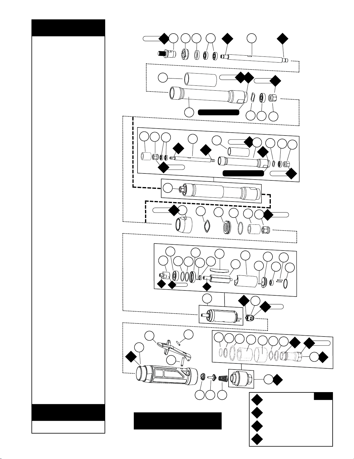
1 53610 3/8-24 Adapter
2 93689 Extension Cap
3 51956 Felt Seal
4 01139 Bearing (2,4,6)
5 93688 Extension Spindle (1,2,3)
6 93687 Extension Housing
7 53690 Grip
8 98325 Wave Washer
9 01007 Bearing (1,2,3)
10 51969 Coupler (2,4,6)
11 53547 Extension Sub Assembly
12 50902 Coupling Insert (1,2,3)
13 93686 Adapter
14 96498 Wave Spring
15 53620 Adapter
16 95438 O-Ring
17 93696 Adapter
18 54520 Bearing
19 01910 Motor Assembly
20 51932 Governor
21 97119 Shim
22 97120 Shim
23 51922 Front Bearing Plate
24 96441 Pin (2)
25 51927 Rotor Spacer
26 51926 Vane (4/Pkg.)
27 51921 Rotor
28 51925 Cylinder
29 51923 Rear Bearing Plate
30 02057 Bearing
31 96445 Pin (2)
32 51924 Gasket
33 All Housings Include:
Warning & Specification Labels
20061 Housing – Model 53531
20062 Housing – Model 53532
20063 Housing – Model 53533
34 51949 Safety Lock Lever
35 96444 Pin
36 51946 V
alve Stem Assembly
37 51945 Valve Seat
38 51944 Tip Valve
39 51943 Spring
40 53655 Muffler Assembly
41 96442 O-Ring
42 51940 Spacer
43 53682 Gasket
44 94528 Felt Silencer
45 53686 Muffler Cap
46 94924 Wave Spring
47 53683 Spacer
48 53681 Inlet Bushing
(Includes. 2 - 51938)
Index Key
No. Part # Description
00001180 Warning Label
00001181 Specification Label
Label Key
Part # Description
Adhesive: A
8
= Loctite #567
A10= Loctite #243
Torque: N•m x 8.85 = In. - lbs.
Grease: G
1
= Lubriplate 630 AA
Oil: O
1
= Air Lube
O
A
T
G
KEY
Complete Assembly
4
17 N•m
T
17 N•m
T
17 N•m
T
35 N•m
T
35 N•m
T
17 N•m
T
17 N•m
T
35 N•m
T
2 N•m
T
17 N•m
T
35 N•m
T
4
5
13
35
34
33
36
37 38 39
20
19
18
21
17
22
23
25
24
26
27
28
24
29
30
31
32
15
16
14
7
8
9
2 3 4
7
11
6
8
9
10
5
A
10
A
10
A
8
A
8
A
10
A
10
O
1
A
8
O
1
A
10
A
10
LEFT HAND THREAD
LEFT HAND THREAD
41
42
43
44
45
46
47
1
A
10
A
8
40
48
6
10
12
10
12
10
Always follow adhesive manufacturers
cleaning and priming recommendations.
Buy parts on line at https://Dynashop.co.uk/ for all things Dynabrade
Buy parts on line at https://Dynashop.co.uk/ for all things Dynabrade
Page 5

Disassembly Instructions - 1hp Extension Cone or Plug Grinders
Important: Manufacturer’s warranty is void if tool is disassembled before warranty expires. Please refer to parts complete tool
assembly for part identification.
Disconnect tool from power source before tool repair.
Extension Disassembly:
1. Remove accessory or abrasive product from the tool assembly.
2. Using 51989 Repair Collar
(
order separately) or padded vise, secure front end of Housing using machined flats on the silver ring.
3. Secure 93686 Adapter with wrench and remove 93687 Extension Housing (LEFT HAND THREAD) from Adapter
(turn extension housing clockwise).
4. Remove 93686 Adapter from motor housing (turn counterclockwise).
5. Secure 51969 Coupler (using 13/16 deep hex socket) remove Threaded Adapter.
6. Secure 93687 Extension Housing, using wrench flats and remove 93689 Extension Cap using 96347 Adjustable Pin Wrench (order separately)
.
7. Pull Extension spindle and bearings from Extension Housing.
Motor Disassembly:
1. Pull motor assembly from housing assembly.
2. Remove governor assembly by using a slotted screw driver (LEFT HAND THREAD, turn clockwise).
3. Secure 51925 Cylinder using 96209 Repair Collar (order separately) and place a 1/8" (3 mm) drift pin to the base of the internal thread
and press the rotor from the 02057 Rear Bearing.
4. Slide 02057 Rear Bearing from 51923 Rear Bearing Plate.
5. Remove 51925 Cylinder and 51926 Blades.
6. Press rotor through 54520 Bearing, 51922 Front Bearing Plate and 51927 Rotor Spacer.
7. Slide 54520 Bearing and shims from 51922 Front Bearing Plate.
Motor Disassembly Complete.
Housing Disassembly:
1. Secure housing using 51989 Repair Collar (
see back cover for Optional Accessories
).
2. Remove inlet bushing with muffler assembly (turn counterclockwise).
3. Remove 53682 Gasket, 51943 Spring, 96442 O-Ring, 51940 Spacer, 94528 Felt Silencer, 53686 Muffler Cap, 94924 Wave Spring and 53683
Spacer from 53681 Inlet Bushing.
4. Remove 51944 Tip Valve and 51945 Valve Seat.
5. Remove housing and 51989 Repair Collar and lay collar on bench with flange facing down so it is supporting throttle lever. Place a 3/32"
(2.4 mm) drift pin on 96444 Pin and tap pin thru housing.
6. Remove 51946 Valve Stem Assembly.
7. Remove 96443 O-Ring from 51946 Valve Stem Assembly.
Housing Disassembly Complete.
Assembly Instructions - 1hp Extension Cone or Plug Grinders
Motor Assembly:
Important: Be sure parts are clean and in good repair before assembling. Follow grease, oil and torque specifications.
1. Place rotor into padded vise with spline facing upwards.
2. Slip 51927 Rotor Spacer over rotor shaft and down against rotor body face.
3. Press 96441 Coiled Pin into 51922 Front Bearing Plate. Make certain, coiled pin does not protrude beyond
internal bearing surface.
4. Place a .002" shim into the base of 51922 Front Bearing Plate as an initial spacing and slide 54520 Bearing to the front plate base.
Note: 51951 Shim Pack contains .001" and .002" shims.
5. Press bearing/bearing plate assembly onto rotor, torque 51969 Coupler onto rotor shaft to 17 N•m (150 lb.-in.).
6. Check clearance between rotor and front bearing plate by using a .001" feeler gauge. Clearance should be between .001" – .0015".
Adjust clearance by repeating steps 4 and 5 with different shims if necessary.
7. Once proper rotor gap clearance is achieved, install well lubricated 51926 Blades (4) into rotor slots. Dynabrade recommends lubricating blades
with 95842 Air Lube.
8. Install 51925 Cylinder over rotor and front plate raised boss. Align coiled pin on front to cylinder slot.
9. Press 96441 Coiled Pin into blind hole on 51923 Rear Bearing Plate. Press (2) 96445 Coiled Pins into the back side of
rear bearing plate.
10. Peel backing off 51924 Gasket and apply it firmly in place onto 51923 Rear Bearing Plate.
11. Place 51923 Rear Bearing Plate over rotor mandrel and insert raised boss on rear bearing plate into cylinder diameter, while inserting
short coiled pin into cylinder slot. Be sure inlet slot on rear bearing plate line up with inlet slot on cylinder. Flip cylinder end to end and
repeat step 8 for correct assembly.
(continued on next page)
5
Buy parts on line at https://Dynashop.co.uk/ for all things Dynabrade
Buy parts on line at https://Dynashop.co.uk/ for all things Dynabrade
Page 6

Assembly Instructions -
(Continued)
Important: Manufacturer’s warranty is void if tool is disassembled before warranty expires.
Please refer to parts breakdown for part identification.
12. Press 02057 Bearing onto rotor and onto 51923 Rear Bearing Plate until it is seated. Important: Cylinder must fit snug between bearing
plates. If too tight, rotor will not turn freely. Rotor must be lightly tapped at press fit end until rotor spins freely while still maintaining a
snug fit. A loose fit will not achieve the proper preload on motor bearing.
(While pressing 02057 Bearing, make certain to contact inner race of bearing only.)
13. Add one drop of Loctite®243 (or equiv.) to governor assembly male thread and screw governor assembly onto place (LEFT HAND
thread) with a slotted screw head. Torque to 2 N•m (18 lb.-in.).
14. Install motor assembly into housing, making sure motor drops all the way into housing. Note: Align both 96445 Coiled Pins to slots in
insert and against 51924 Gasket.
Extension Assembly:
1. Press 01007 onto short end of 93688 Extension Spindle
2. Add one drop of #243 Loctite
®
to spindle thread and torque 51969 Coupler to 17 N•m (150 lb.-in.).
3. Place 98325 Wave Washer into extension housing and slide spindle assembly into extension housing.
4. Slide 01139 Bearings and 51956 Felt Seal onto long end of 93688 Extension Spindle.
5. Tighten 93689 Extension Cap onto housing using 96347 Adjustable Pin Wrench (order separately)
.
6. Secure 51969 Coupler using 13/16" deep hex socket and Torque Threaded Adapter to Spindle Assembly 17 N•m (150 lb.-in.).
7. Add a small amount of #567 Loctite
®
to male thread of 93687 Extension Housing.
8. Align 50902 Coupling Insert onto 51969 Coupler.
9. Secure 93686 Housing Adapter and thread extension to adapter (Left Hand Thread) (turn extension housing counter clockwise).
10. Torque Extension to Adapter to 35 N•m (310 lb.-in.).
Housing Assembly:
1. Secure housing using 51989 Repair Collar,
(see back cover for Optional Accessories)
with collet facing downward.
2. Install 51945 Valve Seat by aligning 3 male prongs with three deep slots on insert. Make certain valve seat is pressed flat against
base of pocket. Note: Add a few drops of Dynabrade Air Lube (P/N 95842) to pocket walls before inserting 51945 Vale Seat.
3. Install 51944 Tip Valve.
4. Pre-assemble muffler, slide 53683 Spacer over 53681 Inlet Bushing and up against the hex head base. Slide 94924 Wave Spring over 53681
Inlet Bushing and up against spacer. Pre roll 94528 Felt and install it in 53686 Muffler Cap. Support felt in felt/muffler cap assembly and slide
53681 Inlet Bushing thru the inside until the muffler cap assembly seats against the 94924 Wave Spring. Flare the felt and place 51940 Spacer
over male thread and set 96442 O-Ring into groove at the base of thread. Return felt to unflared form. Slide 51943 Spring into bushing and up
to the two 51938 screens.
5. Place 53682 Gasket over felt silencer and against 53686 Muffler Cap.
6. Apply one drop of Loctite
®
#243 (or equiv.) to 53681 Inlet Bushing thread.
7. Align small inside diameter of 51943 Spring to cone point on 51944 Tip Valve and thread 53655 Muffler Assembly into place.
Torque bushing to 35 N•m (310 lb.-in.).
8. Slide 96443 O-Ring onto 51946 Valve Stem and slide sub-assembly until o-ring passes through housing hole. Make certain valve stem assembly
slides freely after the o-ring passes through the hole.
9. Remove housing from 51989 Repair Collar and place repair collar onto the bench top with the part number identifier against the bench. Align the
throttle lever holes to housing pin hole and rest the housing and throttle lever onto the legs of the repair collar. Press 96444 Coiled Pin into lever
hole and center into housing.
Tool Assembly Complete. Please allow 30 minutes for adhesives to cure before operating tool.
Important: Before operating, place 2-3 drops of Dynabrade Air Lube (P/N 95842) directly into inlet with throttle lever depressed. Operate tool for 30
seconds to allow air lube to properly lubricate internal motor components. Motor should now be tested for proper operation at 90 PSIG max. If tool
operates at a higher RPM than marked on the tool or if vibration and sound levels seem abnormal, the tool should be serviced to correct
the cause before
use.
6
Loctite®is a registered trademark of Loctite Corp.
Buy parts on line at https://Dynashop.co.uk/ for all things Dynabrade
Buy parts on line at https://Dynashop.co.uk/ for all things Dynabrade
Page 7
This service chart is published as a guide to expectant life of component parts. The replacement levels are based on average tool
usage over one year. Dynabrade Inc. considers one year usage to be 1,000 hours.
Parts Common to all Models:
Preventative Maintenance Schedule
For All 1hp Extension Cone or Plug Grinders
Note: Please refer to page 4 of tool manual for specific part number.
Index Part Description Number High Wear Medium Wear Low Wear Non-Wear
# Number Required 100% 70% 30% 10%
1 53610 Spindle Adapter 1X
2 93689 Extension Cap 1X
3 51956 Felt Seal 1X
4 01139 Bearing See Note X
5 93688 Extension Spindle See Note X
6 93687 Extension Housing 1X
7 53690 Grip 1X
8 98325 Wave Washer 1X
9 01007 Bearing See Note X
10 51969 Coupler See Note X
11 53656 Coupling Insert See Note X
12 93686 Adapter 1X
13 96498 Wave Spring 1T
14 53620 Adapter 1X
15 95438 O-Ring 1T, L
16 93696 Adapter 1X
17 54520 Bearing See Note T
18 51932 Governor 1X
19 97119 Shim 1T, L
20 97120 Shim 1T, L
21 51922 Front Bearing Plate 1X
22 96441 Pin 2L
23 51927 Rotor Spacer 1T
24 51926 Vane (4/Pkg.) 1T
25 51921 Rotor 1X
26 51925 Cylinder 1X
27 51923 Rear Bearing Plate 1X
28 02057 Bearing 1T
29 96445 Pin 2X
30 51924 Gasket 1T
31 See Note Housing 1X
32 51949 Safety Lock Lever 1X
33 96444 Pin 1T
34 51946 Valve Stem Assembly 1T
35 51945 Valve Seat 1X
36 51944 Tip Valve 1T
37 51943 Spring 1X
38 96442 O-Ring 1T, L
39 51940 Spacer 1X
40 53682 Gasket 1X
41 94528 Felt Silencer 1T
42 53686 Muffler Cap 1X
43 94924 Wave Spring 1X
44 53683 Spacer 1X
45 53681 Inlet Bushing 1X
7
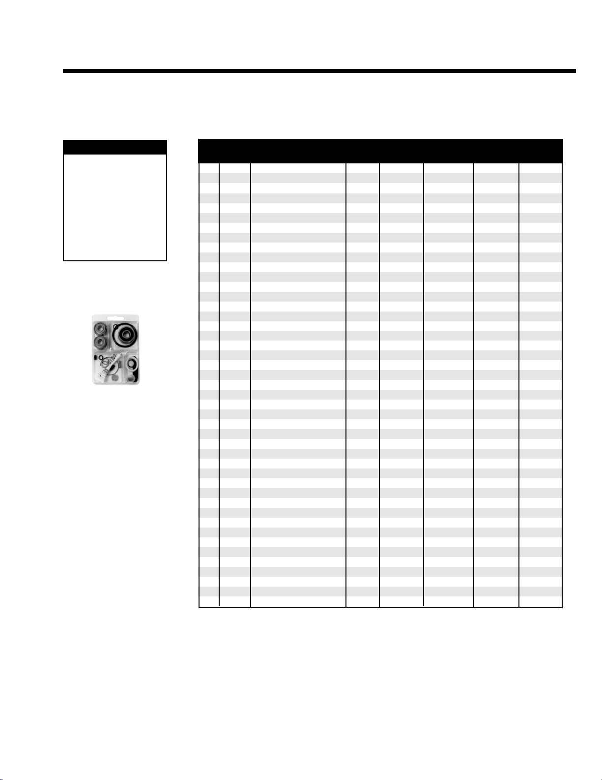
96532 – 1 Hp. Motor Tune-Up Kit
LEGEND
T Part included in 96532
Motor Tune-Up Kit
X Type of wear, no other
comments apply.
L Easily lost. Care during
assembly/disassembly.
D Easily damaged during
assembly/disassembly.
Buy parts on line at https://Dynashop.co.uk/ for all things Dynabrade
Buy parts on line at https://Dynashop.co.uk/ for all things Dynabrade
Page 8
DYNABRADE
®
DYNABRADE, INC.,
8989 Sheridan Drive •Clarence, NY 14031-1490 •Phone: (716) 631-0100 •Fax: 716-631-2073 •International Fax: 716-631-2524
DYNABRADE EUROPE S.àr.l.,
Zone Artisanale •L-5485 Wormeldange—Haut, Luxembourg •Telephone: 352 76 84 94 1 •Fax: 352 76 84 95 1
© DYNABRADE, INC., 2009 PRINTED IN USA PD09.42_rev.1_07/09
Visit Our Web Site: www.dynabrade.com Email: [email protected]
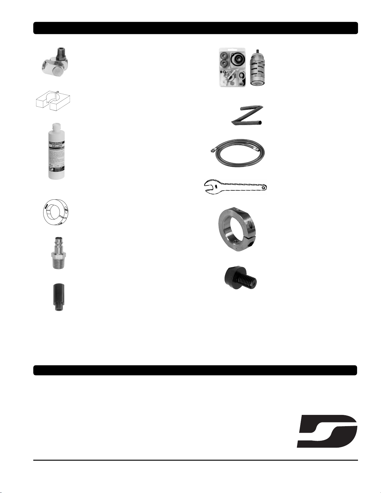
Optional Accessories
Dynaswivel
®
•
Swivels 360° AT TWO PIVOT POINTS allowing the air hose to
drop directly to the floor while providing superb tool handling.
95461 – 3/8" NPT.
51989 Repair Collar
•
Specially designed collar for use in vise to prevent damage
to valve body of tool during disassembly/assembly.
96005 Male Plug
•
Provides up to twice the air flow
compared to standard plug design.
•
Plug has “ported” design to prevent
“starving” of the air tool.
53621 Over Hose Assembly
•
Over Hose Assembly directs exhaust
away from operator.
Dynabrade Air Lube
•
Formulated for pneumatic equipment.
•
Absorbs up to 10% of its weight in water.
•
Prevents rust and formation of sludge.
•
Keeps pneumatic tools operating longer
with greater power and less down time.
95841: 4 oz. (118 ml)
95842: 1pt. (473 ml)
95843: 1 gal. (3.8 L)
96209 Motor Repair Clamp
•
Specially designed clamp to secure motor cylinder
before disassembly.
53199 Collar
•
Specially designed to attach to adapter.
Allows tool to attach to tool hanger.
(With the use of an eye hook.
5/16-18 THD)
Designed to attach to 93686 Adapter.
53652 Threaded Adapter
•
Converts from 3/8"-24 THD to
5/8"-11 THD.
96532 Motor Tune-Up Kit
•
Includes assorted parts to help maintain
and repair motor.
01910 Drop-In Motor
•
Allows quick and easy replacement.
No motor adjustments needed.
Bearing Press Tools
•
Used to install bearings.
96243: For installing 02057 Bearing.
96244: For installing 01007 & 54520 Bearings.
30335 Air Supply Hose
•
3/8 in. I.D. x 60 in. Wide air supply
hose, includes: 3/8 in. NPT male and
female threaded fittings.
Wrenches
95262 – 14 mm open-end.
96347 – Pin Wrench
FIND THE MOST CURRENT OFFERING OF SUPPORT DOCUMENTS AND ACCESSORIES @ WWW.DYNABRADE.COM
Reference Contact Information
1. American National Standards
Institute – ANSI
25 West 43
rd
Street
Forth Floor
New York, NY 10036
Tel: 1 (212) 642-4900
Fax: 1 (212) 398-0023
3. Power Tool Institute, Inc.
P.O. Box 818
Yachata, Oregon 97498-0818
Tel: 1 (503) 547-3185
Fax: 1 (503) 547-3539
4. European Committee for Standardization
Rue de Stassart 36
B - 1050 Brussels, Belgium
2. Government Printing Office – GPO
Superintendent of Documents
Attn. New Orders
P.O. Box 371954
Pittsburgh, PA 15250-7954
Tel: 1 (202) 512-1803
Buy parts on line at https://Dynashop.co.uk/ for all things Dynabrade
Buy parts on line at https://Dynashop.co.uk/ for all things Dynabrade
 Loading...