

Page 1
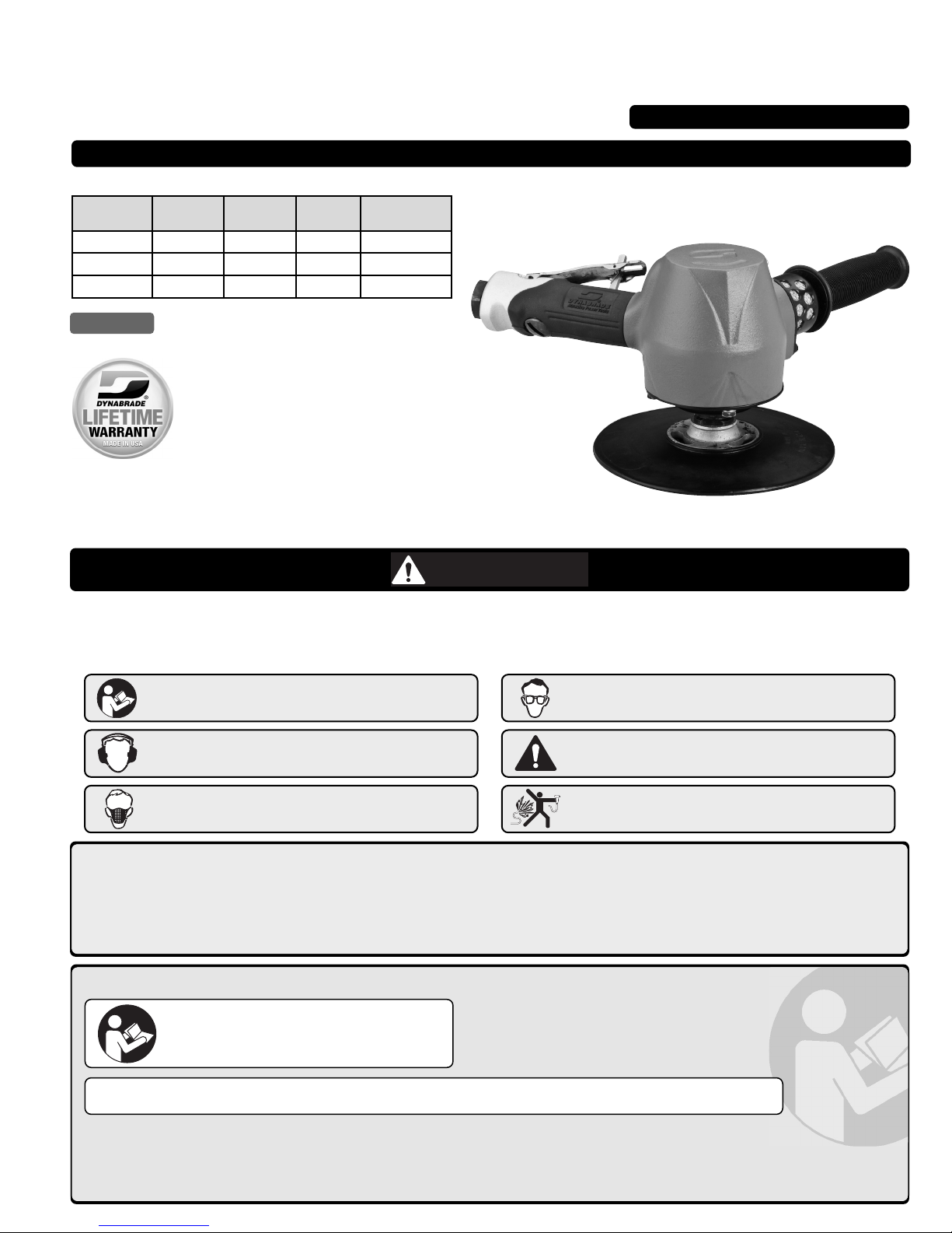
2 hp, Vertical Disc Sander
7" Diameter
Safety, Operation and Maintenance – Save This Document and Educate All Personnel
PD11.28R
March, 2016
Supercedes PD11.28
Model Thread Wheel RPM Exhaust
53251
5/8"-11
7" Dia.
6,000 Side
53252
5/8"-11 7" Dia. 7,200 Side
53253
5/8"-11 7" Dia. 8,500 Side
WARNING
Read and understand this tool manual before operating your air tool. Follow all safety rules for the protection of operating personnel as
well as adjacent areas. Always operate, inspect and maintain this tool in accordance with the American National Standards Institute (ANSI).
Safety Requirements for the Use, Care and Protection of Abrasive Wheels – ANSI B7.1, Compressed Air and Gas Institute (CAGI) Safety Code
for Portable Air Tools – B186.1, Code of Federal Regulation – CFR 29 Part 1910, European Committee for Standards (EN) Hand Held NonElectric Power Tools – Safety Requirements and applicable State and Local Regulations.
Find The Most Current Offering of Support Documents and Accessories at www.Dynabrade.com
Read and understand tool manual before work starts
to reduce risk of injury to operator, visitors, and tool.
Ear protection to be worn when exposure to sound,
exceeds the limits of applicable Federal, State or
local statues, ordinances and/or regulations.
Practice safety requirements. Work alert, have proper
attire, and do not operate tools under the influence
of alcohol or drugs.
Air line hazard, pressurized supply lines and flexible
hoses can cause serious injury. Do not use damaged,
frayed or deteriorated air hoses and fittings.
Eye protection must be worn at all times, eye
protection to conform to ANSI Z87.1.
Respiratory protection to be used when exposed to
contaminants that exceed the applicable threshold
limit values required by law.
Some dust created by sanding, grinding, drilling, and other construction activities contain chemicals known to cause cancer, birth defects
or other reproductive harm. Some examples of these chemicals are:
• Lead from lead-based paints
• Crystalline silica from bricks and cement and other masonry products
• Arsenic and chromium from chemically treated lumber
Your risk from these exposures varies, depending on how often you do this type of work. To reduce your exposure to these chemicals: work in a well
ventilated area, and work with approved safety equipment, such as those dust masks that are specially designed to filter out microscopic particles.
SAFETY INSTRUCTIONS
DO NOT USE Tool for Anything Other Than Its Intended Applications.
Training: Proper care, maintenance, and storage of your air tool will maximize tools performance and reduce chance for accident.
Employer's Responsibility: Provide operators with safety instructions and training for safe use of tools and accessories.
Report to Your Supervisor any Condition of the Tool, Accessories or Operation you Consider Unsafe.
Tool Intent: Disc Sanders are ideal for material removal and finishing applications using properly rated (RPM)
7" diameter abrasives with 7/8" thru hole.
Carefully Read and Understand the General
and Sander/Polisher sections found in Tool
Safety and Operating Guidelines (PN00001676)
Before Handling or Using Tool.
Carefully Read all instructions before operating or servicing
any Dynabrade®Abrasive Power Tool. Products offered by
Dynabrade are not to be modified, converted or otherwise
altered from the original design.
For Serial No. 13H1000A and Higher
GRINDER
Page 2
MAINTENANCE INSTRUCTIONS
Important: To keep tool safe, a Preventative Maintenance Program is
recommended. The program should include inspection of the tool and all
related accessories and consumables, including air lines, pressure regulators,
filters, oilers, etc. (refer to CAGI B186.1 for additional maintenance
information). If accessory or tool breakage occurs, investigate failure to
determine the cause and correct before issuing tool for work. Use the following
schedule as a starting point in developing a Preventative Maintenance
Program. If tool does not operate properly (RPM, vibration, start/stop) after
these scheduled checks or at any time, the tool must be repaired and
corrected before returning tool to use.
INSTALLATION
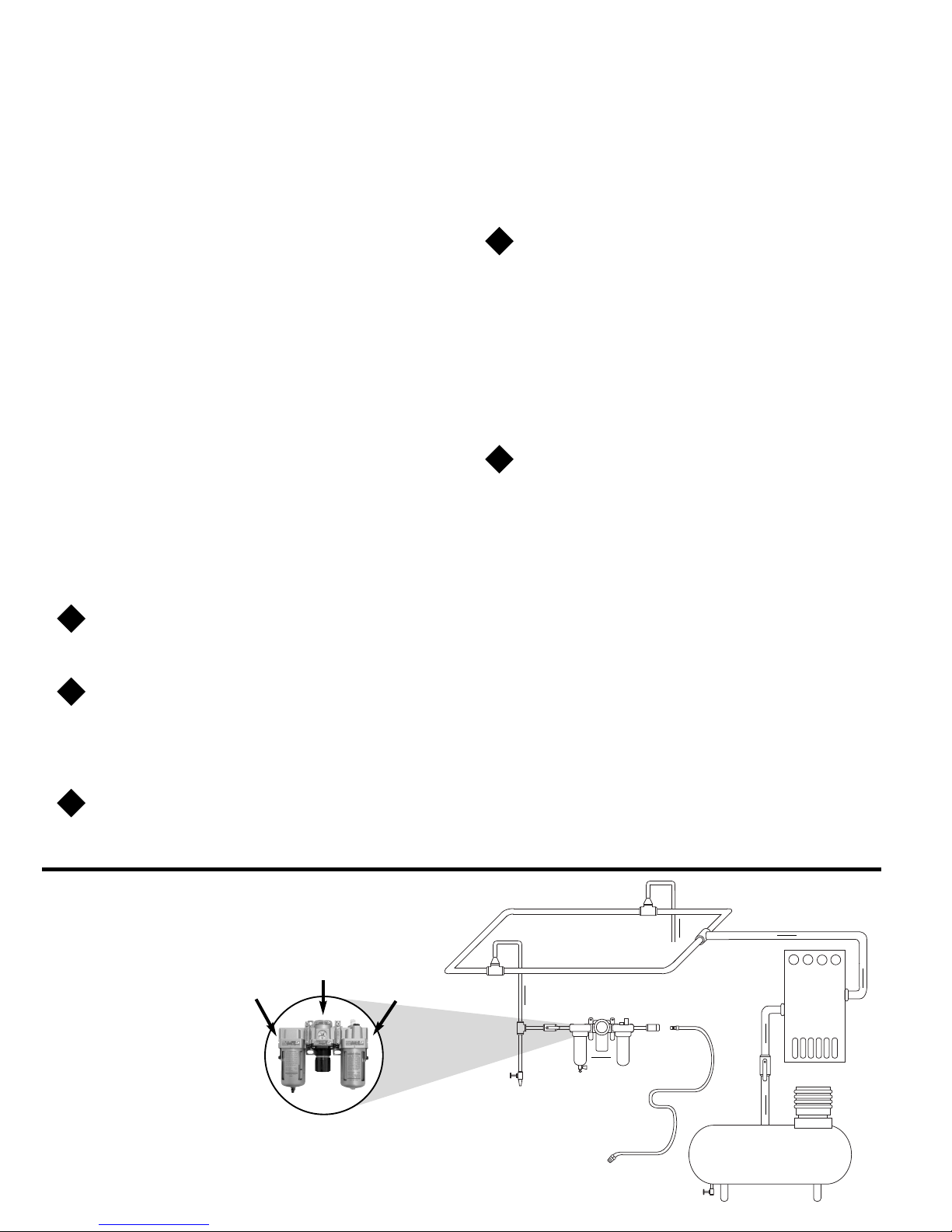
• To ensure long life and dependable service, use a Closed Loop Air System
and Filter-Regulator-Lubricator (FRL) as diagramed below.
• Each tool should have its own dedicated hose connected to an air supply
FRL. Quick disconnects should be installed at the FRL in an effort to reduce
contamination into the tool. Securely affix all fittings and hose assemblies.
• It is strongly recommended that all Dynabrade rotary vane air tools be used
with a Filter-Regulator-Lubricator to minimize the possibility of misuse due
to unclean air, wet air or insufficient lubrication. Dynabrade recommends
the following: 10681 Air Line Filter-Regulator-Lubricator — Provides
accurate air pressure regulation, two-stage filtration of water contaminants
and micro-mist lubrication of pneumatic components.
• Dynabrade recommends 1 drop of air lube per minute for each 20 SCFM
(example: if the tool specification states 40 SCFM, set the drip rate
on the filter-lubricator to 2 drops per minute). 95842 Dynabrade Air Lube
is recommended.
MAINTENANCE SCHEDULE
Maintenance schedules depend on the type and style of tool. Refer to page
3 to reference symbols associated with specific maintenance items/areas.
Match maintenance schedules accordingly. See page 4 for any additional
maintenance information.
Note: Turbine style air motors do not require oil.
Daily (every 8 hours):
• Inspect tool and accessories for damage or broken parts. Replace items
as necessary to ensure proper operation and safety.
Lubricate motor as recommended. Use 95842 Dynabrade Air Lube
(10W/NR). Apply 1 drop/minute of air lube per 20 SCFM.
• Check air line pressure with a gage. (MAX. 90 PSIG or 6.2 Bar operating
pressure at the air inlet of the tool.)
Lubricate wick system and right angle gears through gear case
fitting. Apply 3 plunges of 95848 Gear Oil. Use 95541 Lubricant Gun
(Prime lubricant gun before use).
• Check tool for proper operation: If operating improperly or demonstrates
unusual vibration, the tool must be serviced and problem corrected before
further use.
Every 20 Hours/Once a Week (which ever comes first):
For tools without "wick system", lubricate right angle gears through
lubricant fitting. Apply 1 plunge of 95542 Grease. Use 95541
Lubricant Gun. (Prime lubricant gun before use).
• Measure RPM (speed) by setting air pressure to 90 PSIG (6.2 Bar) at
tool inlet, without accessory mounted, while the tool is running. Using
tachometer, check spindle speed of the tool. Unless otherwise stated the
no-load speed may not exceed the rated speed. If tool speed exceeds
maximum rated RPM, service as required and correct before use.
• If tool is running too fast: look for worn, damaged or missing governor, air
control rings and silencer(s). Service as required.
• If tool is running too slow: look for malfunctioning governor, clogged inlet
screen, silencer(s) or air stream. Service as required.
Note: Special care must be taken when servicing governors. Refer to specific
tool manual for governor instructions and/or speed control devices. Governor
assemblies made from molded plastic components are non-serviceable and
must be replaced.
Every 50 Hours:
Lubricate planetary gears through gear case fitting with 3 plunges
of 95544 Grease. Use 95541 Lubricant Gun. (Prime lubricant gun
before use).
REPAIR
• Use only genuine Dynabrade replacement parts to ensure quality. To order
replacement parts, specify Model#, Serial# and RPM of your air tool.
• Mineral spirits are recommended when cleaning the tool and parts. Do
not clean tool or parts with any solvents or oils containing acids, esters,
ketones, chlorinated hydrocarbons or nitro carbons.
• A Motor Tune-Up Kit is available which includes high wear and medium
wear motor parts.
• Air tool markings must be kept legible at all times, if not, reorder housing
and replace. User is responsible for maintaining specification information.
After maintenance is performed on tool, add a few drops of 95842
Dynabrade Air Lube to the tool inlet and start the tool a few times to
lubricate air motor. Verify RPM (per 20 hr maintenance schedule),
vibration and operation.
HANDLING & STORAGE
• Use of tool rests, hangers and/or balancers is recommended.
• Protect tool inlet from debris (see Notice below).
• Do Not carry tool by air hose or near the tool throttle lever.
• Store accessories in protective racks or compartments to prevent damage.
• Follow the handling instructions outlined in the operating instructions when
carrying the tool and when changing accessories.
• Protect accessories from exposure to water, solvents, high humidity,
freezing temperature and extreme temperature changes.
END OF USE/ DISPOSAL
When tool has reached its end of useful service, disassemble tool into its
primary components (i.e. steel, aluminum and plastic) and recycle or discard
per local, state and/or federal regulations as to not harm the environment.
NOTICE
All Dynabrade air motors use the highest quality parts available and are
manufactured to exacting tolerances. Air motor failures are often traced to lack
of lubrication or unclean air supply. Compressed air can force dirt and other
contaminants into motor bearings causing early failure. Contaminants can score
cylinder wall and vanes resulting in reduced efficiency and power. Our warranty
obligation is contingent upon proper use of our tools. Air motors which have been
subjected to misuse, contaminated air or lack of lubrication will void warranty.
Filter
Regulator
Lubricator
Lubricator Setting
90 PSIG
(6.2 Bar)
Air Flow to Tool Station
Ball
Valve
Ball
Valve
Air Flow
Drain
Valve
Drain
Valve
Air Tool
Air Compressor and Receiver
Drain Valve
Air Hose
90 PSIG Max.
(6.2 Bar)
Air Flow
Refrigerated
Air Dryer
• Dynabrade Air Power Tools
are designed to operate at 90
PSIG (6.2 Bar) maximum air
pressure at the tool inlet,
when the tool is running. Use
recommended regulator to
control air pressure.
• Ideally the air supply should
be free from moisture. To
facilitate removing moisture
from air supply, the installation
of a refrigerated air dryer after
the compressor and the use of
drain valves at each tool
station is recommended.
‰
‰
‰
‰
‰
‰
CLOSED LOOP AIR SYSTEM
Sloped in Direction of Air Flow
O
W
G
O
2
‰
~
1 Drop/Minute per 20 SCFM
G
Page 3
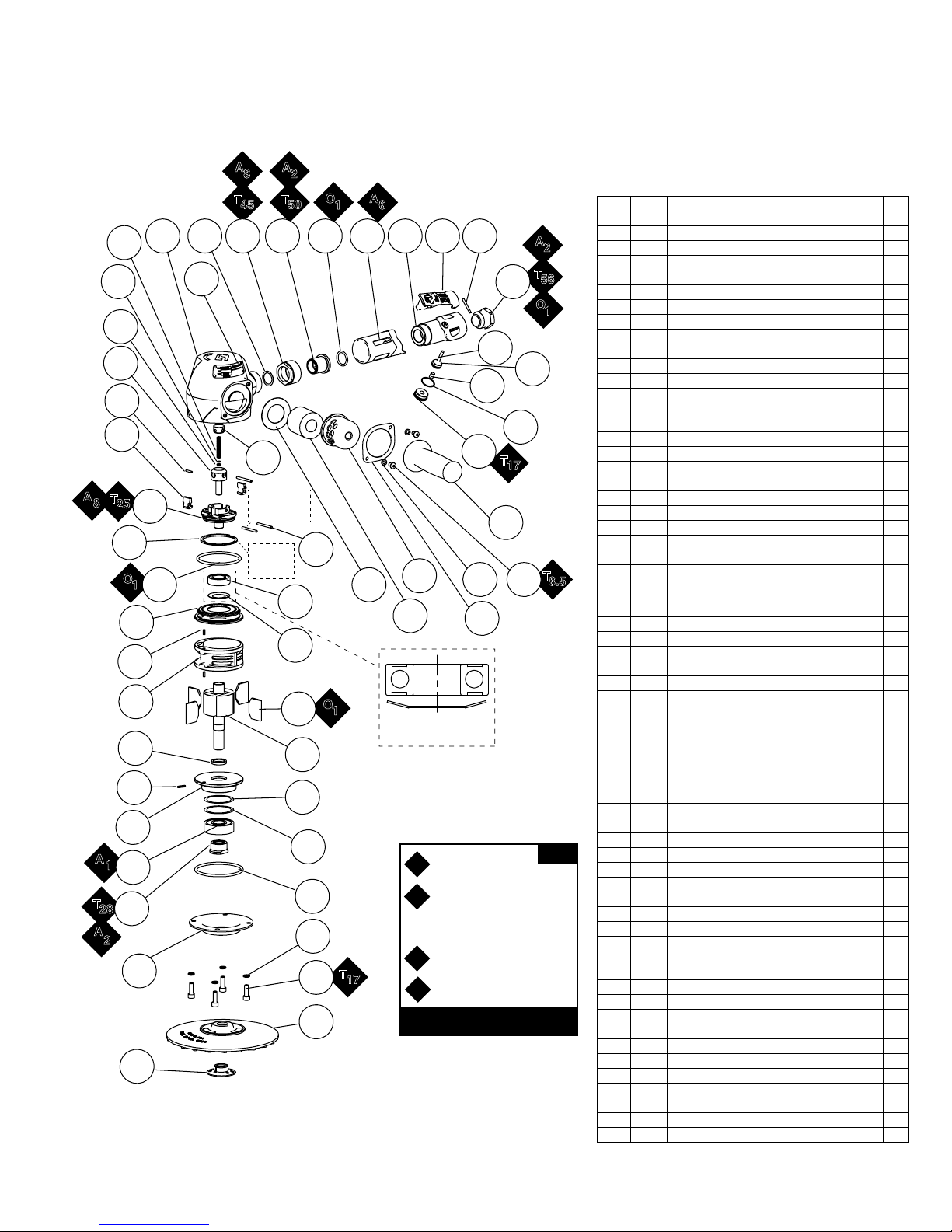
Vertical Disc Sander
Complete Assembly
Models
53251
- 6,000 RPM
53252
- 7,200 RPM
53253
- 8,500 RPM
3
ITEM P/N DESCRIPTION QTY.
1 50268 FLANGE 1
2 50283 7" DIA. SANDING PAD
(INC. 50268 FLANGE NUT) 1
3 50508 SCREW 4
4 95757 WASHER 4
5 55226 HOUSING COVER 1
6 95881 O-RING 1
7 02410 MOTOR ASSEMBLY 1
7.1 55236 NUT 1
7.2 01825 BEARING 1
7.3 52469 SHIM - 0.6 MM THK AR
7.4 52470 SHIM - 1.9 MM THK AR
7.5 55203 FRONT BEARING PLATE 1
7.6 95240 PIN 1
7.7 55223 SPACER 1
7.8 55240 ROTOR 1
7.9 55242 VANE (4/PKG) 1
7.10 55241 CYLINDER ASSEMBLY 1
7.10.1 01673 PIN 2
7.11 55202 REAR BEARING PLATE 1
7.12 55216 WASHER 1
7.13 02552 BEARING 1
8 95880 O-RING 1
9.1 55227 GOVERNOR BODY 1
9.2 95578 SLOTTED PIN 3
9.3
55213
55214
55215
GOVERNOR WEIGHT - 53251
GOVERNOR WEIGHT - 53252
GOVERNOR WEIGHT - 53253
2
9.4 95240 PIN 1
9.5 55206 GOVERNOR VALVE 1
9.6 95337 GOVERNOR SHIM - 0.8 MM THK AR
9.7 95915 GOVERNOR SHIM - 0.4 MM THK AR
9.8 55209 SPRING 1
9.9 55207 GOVERNOR CAP 1
9.10
55218
55219
55220
OVERSPEED SHUT-OFF RING - 53251
OVERSPEED SHUT-OFF RING - 53252
OVERSPEED SHUT-OFF RING - 53253
1
10
02444
02445
02446
HOUSING ASSEMBLY - 53251
HOUSING ASSEMBLY - 53252
HOUSING ASSEMBLY - 53253
1
10.1
55272
55273
55274
LABEL - 53251
LABEL - 53252
LABEL - 53253
1
11 52496 PACKING 1
12 52495 CUP NUT 1
13 52491 BUSHING 1
14 01746 O'RING 1
15 52441 THROTTLE HANDLE ASSEMBLY 1
15.1 07136 HANDLE GRIP 1
15.2 52494
THROTTLE HANDLE (INC. 07142 BUSHING)
1
15.3 01953 SAFETY LOCK LEVER 1
15.4 01017 PIN 1
15.5 01697 INLET BUSHING ASSEMBLY 1
15.6 07168 VALVE STEM ASSEMBLY 1
15.6.1 96577 O-RING 1
15.7 07145 SPRING 1
15.8 07146 PACKING 1
15.9 07147 PLUG 1
16 52169 HANDLE ASSEMBLY 1
17 96274 SCREW 2
18 01791 WASHER 2
19 52180 EXHAUST CLAMP 1
20 52164 EXHAUST COVER 1
21 55245 SILENCER 1
22 52165 GASKET 1
— 95304 WRENCH - 24 MM 1
Adhesive: A1= Loctite #609
A
2
= Loctite #271
A
6
= Loctite #380
A
8
= Loctite #567
Oil: O1= Air Lube
O
A
T
T
x
KEY
Always follow adhesive manufacturers
cleaning and priming recommendations.
Torque: N•m x 8.85 = lb•in.
X = Torque Value (N•m)
A
T
11 15.2
10
9.8
9.7
9.6
9.5
9.4
9.3
A
T
8
25
9.10
O
1
7.11
7.10.1
7.10
7.7
7.6
7.5
A
1
7.2
T
7.1
28
A
2
5
1
10.1
9.1
8
A
8
2
O
T
45
12 13 15.3 15.4
50
14
A
1
6
15.1
15.7
9.9
Orient Slot on
Pins to Face
Upward
See Pg.4
Governor
Details
9.2
22
20
15.9
18 17
7.13
21
19
7.12
O
7.9
1
PROPER ORIENTATION
OF SPRING WASHER
7.8
7.4
7.3
6
4
T
3
17
2
15.5
15.6
15.8
T
17
16
A
T
O
15.6.1
2
56
1
T
8.5
Page 4
DYNABRADE, INC. www.dynabrade.com
8989 Sheridan Drive •Clarence, NY 14031-1419 •Phone: 716-631-0100 •Fax: 716-631-2073 •International Fax: 716-631-2524
© DYNABRADE, INC., 2016
MACHINE SPECIFICATIONS
LIFETIME WARRANTY
To validate Dynabrade Lifetime Warranty, you must register each tool at: www.dynabrade.com. Registration of each tool at website is required.
Dynabrade will not honor Lifetime Warranty on unregistered tools. Please view the entire Lifetime Warranty Policy at : www.dynabrade.com.
Additional Specifications: Air Inlet Thread 1/2" NPT • Hose I.D. 1/2" (13 mm)
Sound Level is the pressure measurement according to the method outlined in ISO regulation ISO-15744
Model Speed Power Sound Air Consumption Wheel Size Weight Length Height
53251 6,000 RPM 2 hp (1491 W) 81 db(A) 80 SCFM (2265 LPM) 7" Dia. 7.9 lb. (3.6 kg) 9.4" (240 mm) 5.8" (148 mm)
53252 7,200 RPM 2 hp (1491 W) 81 db(A) 87 SCFM (2264 LPM) 7" Dia. 7.9 lb. (3.6 kg) 9.4" (240 mm) 5.8" (148 mm)
53253 8,500 RPM 2 hp (1491 W) 80 db(A) 84 SCFM (2379 LPM) 7" Dia. 7.9 lb. (3.6 kg) 9.4" (240 mm) 5.8" (148 mm)
OPTIONAL ACCESSORIES
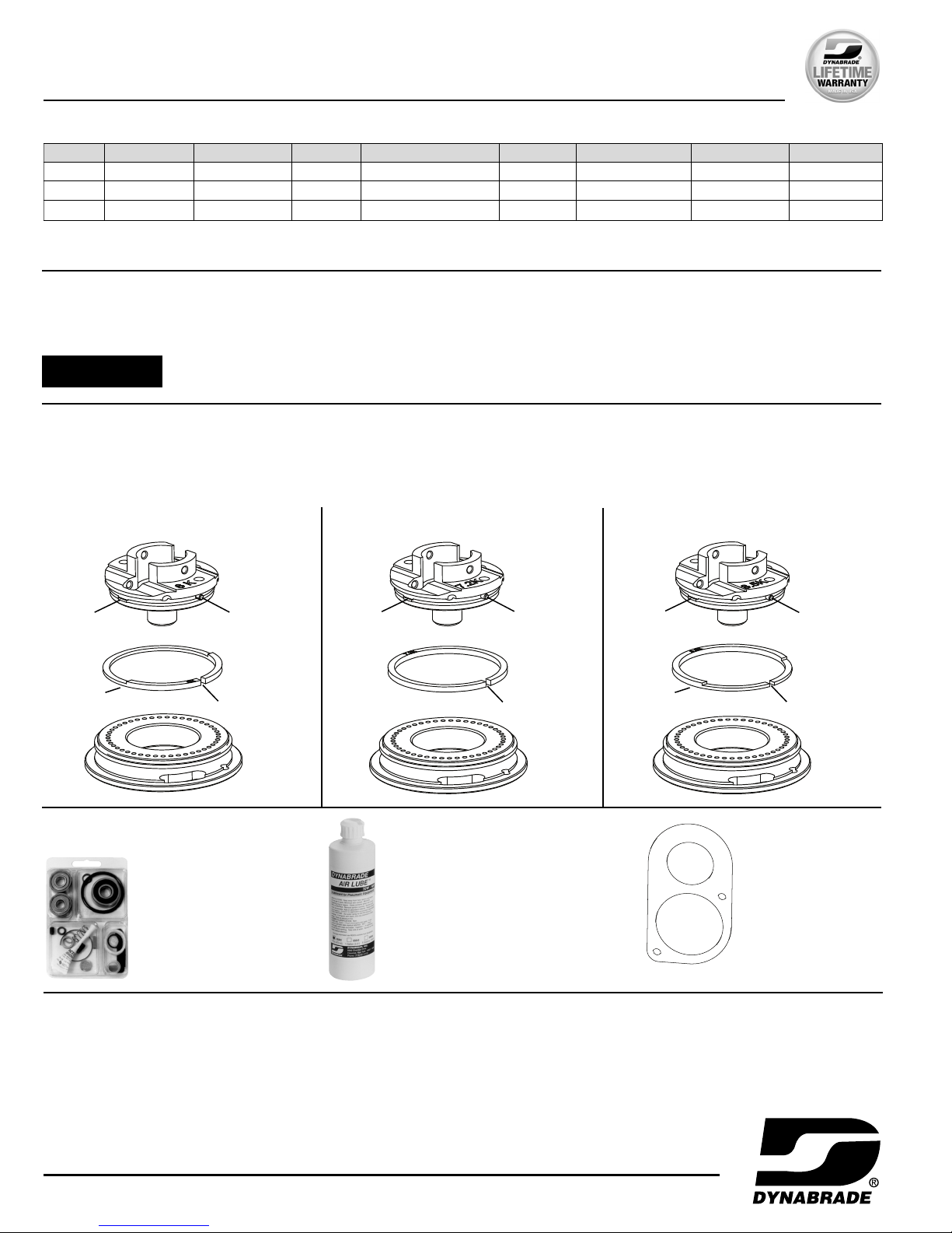
GOVERNOR ASSEMBLY – PROPER ORIENTATION OF OVERSPEED SHUT-OFF RING
OVERSPEED SHUT-OFF RING
If the tool stops suddenly or does not reach the rated tool speed, the overspeed shut-off ring may have activated, closing off the inlet air supply.
The tool must be serviced to correct the problem and the overspeed shut-off ring must be properly reinstalled for safe use.
DANGER
IMPROPER INSTALLATION OR SERVICING OF OVERSPEED SHUT-OFF RING MAY RESULT IN SERIOUS INJURY OR DEATH.
BEST SERVICED BY FACTORY
6,000 RPM 7,200 RPM 8,500 RPM
INSTALL SHUT-OFF RING OVER BOTH TAB FEATURES ON THE GOVERNOR BODY WITH SLOT FEATURE CENTERED ON THE PIN.
IMPORTANT:
ORIENT FLAT SIDE OF SHUT-OFF RING TOWARD BEARING PLATE.
Flat Side
Tab
Pin
Governor
Body
Overspeed
Shut-Off Ring
Bearing
Plate
Governor
Body
Overspeed
Shut-Off Ring
Bearing
Plate
Bearing
Plate
Governor
Body
Overspeed
Shut-Off Ring
Slot
Tab
Pin
Slot
Flat Side
Tab
Pin
Slot
Motor Tune-Up Kit
•
Includes assorted
parts to help maintain
and repair motor.
Part No. 96552
Hanger Bracket
•
For use with hangers
and suspension devices.
Part No. 55248
Dynabrade Air Lube
•
Formulated for pneumatic equipment.
•
Absorbs up to 10% of its weight in water.
•
Prevents rust and formation of sludge.
•
Keeps pneumatic tools operating longer
with greater power and less down time.
Part No. 95842: 1pt. (473 ml)
Part No. 95843: 1 gal. (3.8 L)
American National Standards Institute (ANSI)
25 West 43 Rd St., 14th Floor • New York, NY 10036 • Tel: 1 (202) 293-8020
Compressed Air & Gas Institute
1300 Sumner Ave. • Cleveland, OH 44115-2851
Tel: 1 (216) 241-7333 • Fax. (216) 241-0105
European Committee for Standardization
Rue de Stassart 36 • B - 1050 Brussels, Belgium
International Organization of Standards
Case postale 56 • CH-1211 Geneva 20
Tel: + 41 22 749 01 11 • Fax: + 41 22 749 09 47
Government Printing Office
Superintendent of Documents • Attn: New Orders
P.O. Box 371954 • Pittsburgh, PA 15250-7954
Tel: 1 (202) 512-1803
REFERENCE CONTACT INFORMATION
 Loading...