

Page 1
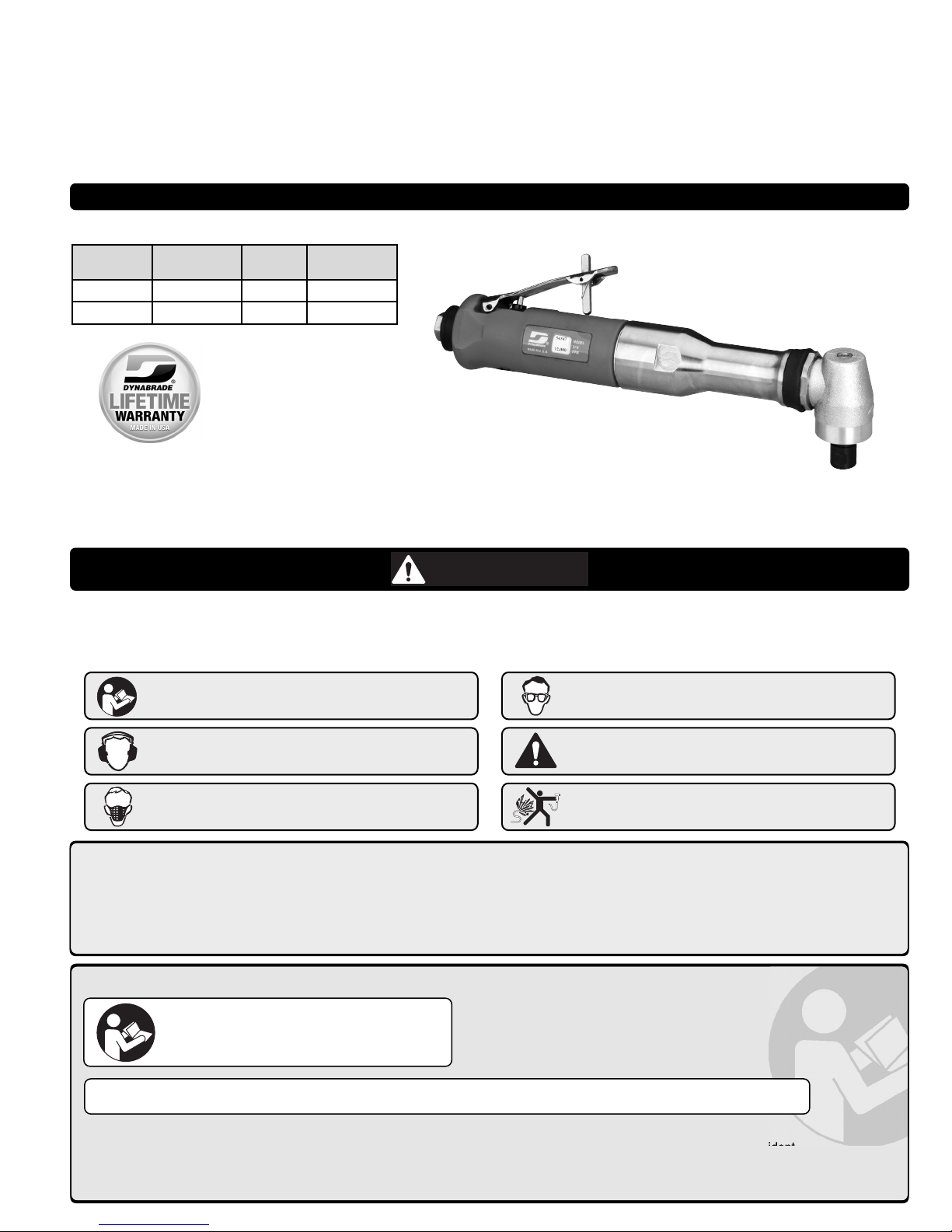
.7 hp Extension Die Grinder
Composite Housing, Right Angle
Parts Page Reorder No. PD11•04
Effective January, 2011
Model 54347
Model Collet RPM Exhaust
54347
1/4" & 6 mm 12,000 Rear
54363
1/4" & 6 mm 18,000 Rear
WARNING
Read and understand this tool manual before operating your air tool. Follow all safety rules for the protection of operating personnel
as well as adjacent areas. Always operate, inspect and maintain this tool in accordance with the American National Standards
Institute (ANSI) Safety Code for Portable Air Tools – B186.1. For additional safety information, refer to Safety Requirements for the Use,
Care and Protection of Abrasive Wheels – ANSI B7.1, Code of Federal Regulation – CFR 29 Part 1910, European Committee for Standards
(EN) Hand Held Non-Electric Power Tools – Safety Requirements and applicable State and Local Regulations.
Find The Most Current Offering of Support Documents and Accessories at www.Dynabrade.com
Read and understand tool manual before work starts
to reduce risk of injury to operator, visitors, and tool.
Ear protection to be worn when exposure to sound,
exceeds the limits of applicable Federal, State or
local statues, ordinances and/or regulations.
Practice safety requirements. Work alert, have proper
attire, and do not operate tools under the influence
of alcohol or drugs.
Air line hazard, pressurized supply lines and flexible
hoses can cause serious injury. Do not use damaged,
frayed or deteriorated air hoses and fittings.
Eye protection must be worn at all times, eye
protection to conform to ANSI Z87.1.
Respiratory protection to be used when exposed to
contaminants that exceed the applicable threshold
limit values required by law.
Safety, Operation and Maintenance –Save This Document and Educate All Personnel
Some dust created by sanding, grinding, drilling, and other construction activities contain chemicals known to cause cancer, birth defects
or other reproductive harm. Some examples of these chemicals are:
• Lead from lead-based paints
• Crystalline silica from bricks and cement and other masonry products
• Arsenic and chromium from chemically treated lumber
Your risk from these exposures varies, depending on how often you do this type of work. To reduce your exposure to these chemicals: work in a well
ventilated area, and work with approved safety equipment, such as those dust masks that are specially designed to filter out microscopic particles.
DO NOT USE Tool for Anything Other Than Its Intended Applications.
Training: Proper care, maintenance, and storage of your air tool will maximize tools performance and reduce chance for accident.
Employer's Responsibility: Provide operators with safety instructions and training for safe use of tools and accessories.
Report to Your Supervisor any Condition of the Tool, Accessories or Operation you Consider Unsafe.
Tool Intent: Die Grinders are ideal for deburring, deflashing, surface preparation, cleaning and finishing using the
proper abrasive stones, abrasive mounted wheels and points, mounted abrasives and carbide burrs.
SAFETY and OPERATING INSTRUCTIONS
Carefully Read and Understand the General
and Die Grinder sections found in Tool Safety
and Operating Guidelines (PN00001676)
Before Handling or Using Tool.
Carefully Read all instructions before operating or servicing
any Dynabrade®Abrasive Power Tool. Products offered by
Dynabrade are not to be modified, converted or otherwise
altered from the original design.
Page 2
2
MAINTENANCE INSTRUCTIONS
Important: To keep tool safe, a Preventative Maintenance Program is
recommended. The program should included inspection of the tool and all
related accessories and consumables, including air lines, pressure regulators,
filters, oilers, etc. refer to ANSI B186.1 for additional maintenance information.
If accessory or tool breakage occurs, investigate failure to determine the
cause and correct before issuing tool for work. Use the following schedule as
a starting point in developing a Preventative Maintenance Program. If tool
does not operate properly (RPM, Vibration, Start/Stop) after these scheduled
checks or at any time, the tool must be repaired and corrected before returning
tool to use.
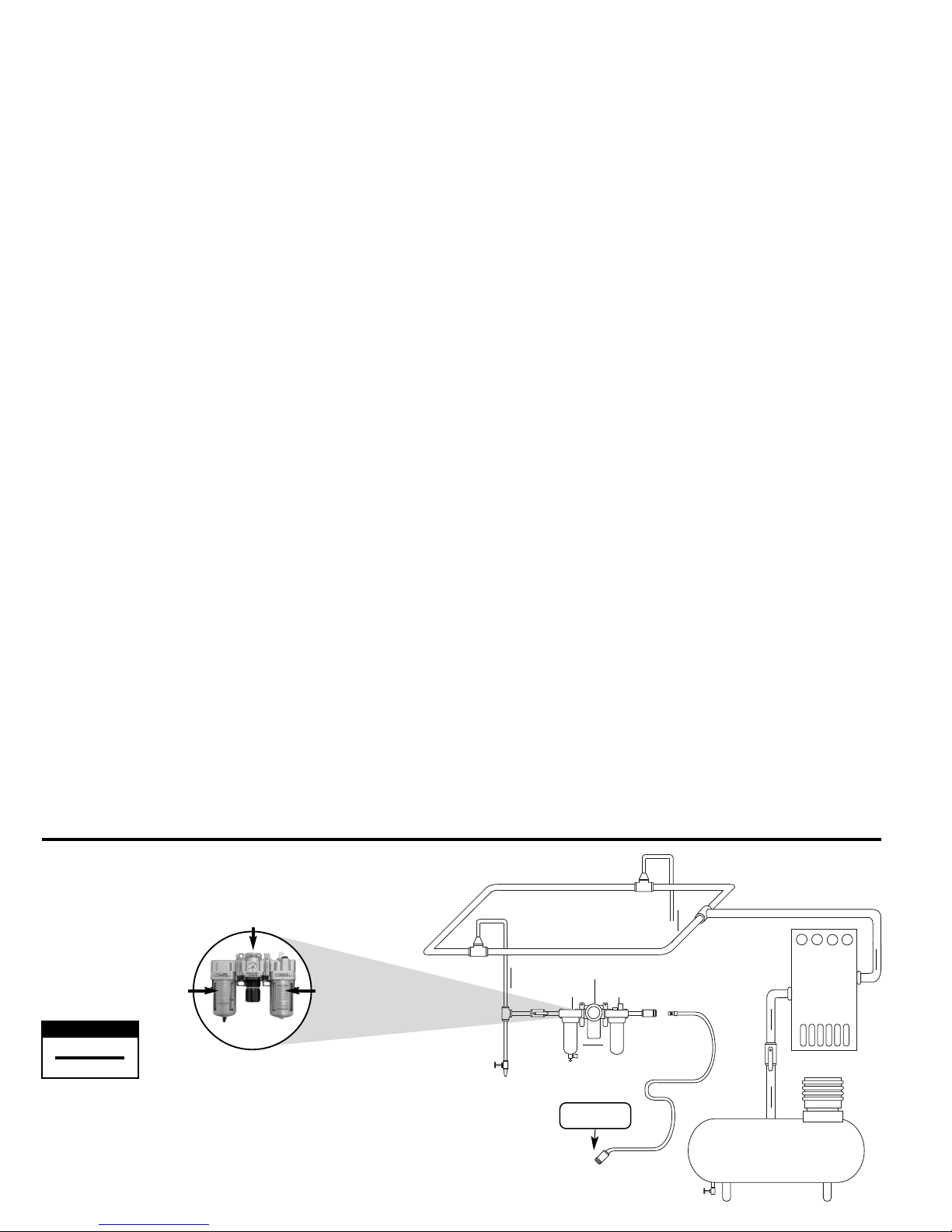
INSTALLATION
• To ensure long life and dependable service, use a Closed Loop Air System
and Filter-Regulator-Lubricator as diagramed below.
• Each tool should have its own dedicated hose connected to an air supply
manifold. Quick disconnects should be installed at the manifold in an effort
to reduce contamination into the tool.
• It is strongly recommended that all Dynabrade rotary vane air tools be used
with a Filter-Regulator-Lubricator to minimize the possibility of misuse due
to unclean air, wet air or insufficient lubrication. Dynabrade recommends
the following: 10681 Air Line Filter-Regulator-Lubricator — Provides
accurate air pressure regulation, two-stage filtration of water contaminants
and micro-mist lubrication of pneumatic components.
• Dynabrade recommends one drop of air lube per minute for each 20 SCFM
(example: if the tool specification states 40 SCFM, set the drip rate on the
filter-lubricator to 2 drops per minute) Dynabrade Air Lube (P/N 95842:
1pt/473ml) is recommended.
MAINTENANCE SCHEDULE
Daily (every 8 hours):
• Inspect tool and accessories for damage or broken parts. Replace items
as necessary to ensure proper operation and safety.
• Lubricate motor as recommended. Use Dynabrade Air Lube (P/N 95842:
1pt/473ml) 10W/NR. (1 Drop per minute of air lube per 20 SCFM.)
• Check air line pressure with a gage. (MAX. 90 PSIG or 6.2 Bar operating
pressure at the air inlet of the tool.)
• Right angled gear and wick system through gear case grease fitting with
3 plunges of gear oil (P/N 95848) and grease gun (P/N 95541). (Prime
grease gun prior to greasing.)
• Check tool for proper operation: If operating improperly or demonstrates
unusual vibration, the tool must be serviced and problem corrected before
further use.
Every 20 Hours or Once a Week Which Ever Comes First:
• Check free speed of tool without the abrasive accessory mounted. Measure
RPM (speed) with tachometer and with air pressure set at 90 PSIG while the
tool is running. If a governed tool is operating at a higher speed than the
RPM marked on the tool housing, the tool must be serviced and corrected
before use. A non-governed tool may exceed the RPM marked on the tool
by 10% when operated at free speed with no accessories.
• If tool is running fast look for worn, damaged or missing governors, air
control rings and silencers. Special care must be taken when servicing
governors and speed control devices. Injection molded governor assemblies
are non-serviceable and must be replaced.
• If tool is running slow look for clogged inlet screen, air stream, silencer(s)
or a malfunctioning governor (see concerns for servicing governors).
Service as required.
Every 50 Hours:
• Lubricate planetary gears through gear case grease fitting with 3 plunges
of grease (P/N 95542) and grease gun (P/N 95541). (Prime grease gun
prior to greasing.)
REPAIR
• Use only genuine Dynabrade replacement parts to ensure quality. To order
replacement parts, specify Model#, Serial# and RPM of your air tool.
• Mineral spirits are recommended when cleaning the tool and parts. Do
not clean tool or parts with any solvents or oils containing acids, esters,
ketones, chlorinated hydrocarbons or nitro carbons.
• DO NOT clean or maintain tools with chemicals that have a low flash point
(example: WD-40
®
).
• A Motor Tune-Up Kit is available which includes high wear and medium
wear motor parts.
• Air tool markings must be kept legible at all times, if not, reorder housing
and replace. User is responsible for maintaining specification information.
• After maintenance is performed on tool, add a few drops of Dynabrade
Air Lube (P/N 95842) to the tool inlet and start the tool a few times
to lubricate air motor. Verify RPM (per 20 hr maintenance schedule),
vibration and operation.
HANDLING & STORAGE
• Use of tool rests, hangers and/or balancers is recommended.
• Protect tool inlet from debris (see Notice).
• DO NOT carry tool by air hose or near the tool throttle lever.
• Store accessories in protective racks or compartments to prevent damage.
• Follow the handling instructions outlined in the operating instructions when
carrying the tool and when changing accessories.
• Protect accessories from exposure to water, solvents, high humidity,
freezing temperature and extreme temperature changes.
END OF USE/ DISPOSAL
When tool has reached its end of useful service, disassemble tool into its
primary components (i.e. steel, aluminum and plastic part) and recycle or
discard per local, state and/or federal regulations as to not harm the
environment.
NOTICE
All Dynabrade motors use the highest quality parts and metals available and
are machined to exacting tolerances. The failure of quality pneumatic motors
can most often be traced to an unclean air supply or the lack of lubrication.
Air pressure easily forces dirt or water contained in the air supply into motor
bearings causing early failure. It often scores the cylinder walls and the rotor
blades resulting in limited efficiency and power. Our warranty obligation is
contingent upon proper use of our tools and cannot apply to equipment
which has been subjected to misuse such as unclean air, wet air or a lack
of lubrication during the use of this tool.
2
Filter
Regulator
Lubricator
90 PSIG
(6.2 Bar)
To Tool Station
Ball
Valve
Ball
Valve
Filter
Regulator
Lubricator
Air Flow
Drain
Valve
Drain
Valve
Air Tool
Air Compressor
and Receiver
Drain Valve
Air Hose
90 PSIG MAX
(6.2 Bar)
Air Flow
Refrigerated
Air Dryer
• Dynabrade Air Power Tools are designed to operate at 90 PSIG
(6.2 Bar) maximum air pressure at the tool inlet, when the tool is
running. Use recommended regulator to control air pressure.
• Ideally the air supply should be free from moisture. To facilitate
removing moisture from air supply, the installation of a refrigerated
air dryer after the compressor and the use of drain valves at each
tool station is recommended.
➤
➤
➤
➤
➤
➤
AIR SYSTEM
Closed Loop Pipe System, Sloped in Direction of Air Flow
1 DROP/MIN.
20 SCFM
LUBRICATOR SETTING
Page 3

.7 hp Extension Die Grinder, Composite Housing
Complete Assembly
Models
54347
54363
AR – “As Required”
ITEM P/N DESCRIPTION QTY.
1 01484 COLLET CAP 1
2
01485
01497
1/4" INSERT
6 mm INSERT
1
3 02035 LOCK NUT 1
4 01486 FELT SILENCER 1
5 02032 COLLET BODY 1
6 54520 BEARING 2
7 97116 SHIM - 0.025 THK AR
8 97117 SHIM - 0.05 THK AR
9 97118 SHIM - 0.127 THK AR
10
02599
02589
GEAR - 54347
GEAR - 54363
1
11
02044
02042
BOTTOM WICK - 54347
BOTTOM WICK - 54363
1
12 02045 TOP WICK 1
13 02031 HOUSING ASSEMBLY 1
13.1 02033 BEARING 1
13.2 02041 LUBE PLATE 1
13.3 01041 FITTING 1
14 01461 LOCK RING 1
15 01547 INSULATION COLLAR 1
16
02600
02590
PINION - 54347
PINION - 54363
1
17 02649 BEARING 1
18 53579 EXTENSION HOUSING 1
19 53564 EXTENSION SPINDLE 1
20 98505 WAVE WASHER 1
21 51969 COUPLING NUT 1
22 50902 COUPLER 1
23 53574 SPACER 1
24 01882 MOTOR ASSEMBLY 1
24.1 51969 COUPLING NUT 1
24.2 01007 BEARING 1
24.3 01293 SHIM - 0.025 THK AR
24.4 01294 SHIM - 0.05 THK AR
24.5 52924 FRONT BEARING PLATE 1
24.6 01010 SPACER 1
24.7 02373 ROTOR 1
24.8 01185
VANE (4/PKG)
1
24.9 01028 CYLINDER 1
24.10 50767 PIN 1
24.11 01721 REAR BEARING PLATE 1
24.12 02649 BEARING 1
25 01017 PIN 1
26 95558 RETAINER RING 1
27 01089 SAFETY-LOCK THROTTLE LEVER 1
28 01477 VALVE STEM 1
29 01464 SEAL 1
30 01472 TIP VALVE 1
31 01468 SPRING 1
32
01568
01564
AIR CONTROL RING - 54347
AIR CONTROL RING - 54363
1
33 01247 SPEED REGULATOR 1
34 01024 O-RING 1
35 95730 O-RING 1
36
25107
25123
MOTOR HOUSING - 54347
MOTOR HOUSING - 54363
1
36.1 96119 SPECIFICATION LABEL 1
36.2 96191 WARNING LABEL 1
37 94535 MUFFLER ASSEMBLY 1
37.1 95711 SNAP RING 1
37.2 01486 FELT SILENCER 4
37.3 96065 O'RING 1
37.4 01446 AIR DEFLECTOR 1
37.5 95620 RETAINING RING 1
37.6 01578 INLET ADAPTER 1
— 95262 WRENCH - 14MM 2
3
Adhesive: A4= Loctite #680
A
8
= Loctite #567
A10= Loctite #243
Oil: O1= Air Lube
Wick: W
1
= Gear Oil
O
W
A
T
T
x
Always follow adhesive manufacturers
cleaning and priming recommendations.
Torque: N•m x 8.85 = lb•in.
X = Torque Value (N•m)
KEY
A
4
W
1
T
15
24.1
A
37.1
17
16
24.2
26
36.1
10
13.2
13.1
13.3
LH
A
10
14
T
34
13
10
9
T
17
12
8
W
1
7
11
6
A
5
8
T
23
4
A
8
3
T
23
2
1
25
24.3
33
37.2
17
24.4
37.3
T
18
27
34
24.5
28
35
34
37.4
19
24.6
29
36.2
37.5
24.7
36
20
30
31
37.6
A
T
23
A
T
17
10
21 2322
6
24.12
24.11
24.9
24.10
O
1
24.8
32
O
1
8
Page 4

DYNABRADE, INC. www.dynabrade.com
8989 Sheridan Drive •Clarence, NY 14031-1419 •Phone: (716) 631-0100 •Fax: 716-631-2073 •International Fax: 716-631-2524
© DYNABRADE, INC., 2011 PRINTED IN USA PD11.04_01/11
1. American National Standards
Institute – ANSI
25 West 43rdStreet
Fourth Floor
New York, NY 10036
Tel: 1 (212) 642-4900
3. Power Tool Institute, Inc.
P.O. Box 818
Yachata, Oregon 97498-0818
Tel: 1 (503) 547-3185
2. Government Printing Office –
GPO
Superintendent of Documents
Attn. New Orders
P.O. Box 371954
Pittsburgh, PA 15250-7954
Tel: 1 (202) 512-1803
REFERENCE CONTACT INFORMATION
4. European Committee for
Standardization
Rue de Stassart 36
B - 1050 Brussels, Belgium
LIFETIME WARRANTY
To validate Dynabrade Lifetime Warranty, you must register each tool at: www.dynabrade.com. Registration of each tool at website is required.
Dynabrade will not honor Lifetime Warranty on unregistered tools. Please view the entire Lifetime Warranty Policy at : www.dynabrade.com.
OPTIONAL ACCESSORIES
MACHINE SPECIFICATIONS
Model Speed Power Sound Air Consumption Collet - 300 Series Weight Length Height
54347 12,000 RPM .7 hp (522 W) 80 db(A) 40 SCFM (1133 LPM) 1/4" & 6 mm 3 lb. (1.4 kg) 11.3" (287 mm) 2.9" (74 mm)
54363 18,000 RPM .7 hp (522 W) 80 db(A) 41 SCFM (1161 LPM) 1/4" & 6 mm 3 lb. (1.4 kg) 11.3" (287 mm) 2.9" (74 mm)
Additional Specifications: Air Inlet Thread 1/4" NPT • Hose I.D. 3/8" (10 mm)
Sound Level is the pressure measurement according to the method outlined in ISO regulation ISO-15744
Motor Tune-Up Kit
•
Includes assorted parts to help
maintain and repair motor.
Part No. 96680
Over Hose Assembly
•
Over Hose Assembly directs
exhaust away from operator.
Part No. 94994
Dynabrade Angle Gear Oil
•
Specifically formulated to saturate
wick system in right angle gear head.
Part No. 95848: 2.5 oz. tube
Part No. 95541: Gear Oil Gun
 Loading...