

Page 1
SAFETY INSTRUCTIONS
Carefully Read all instructions before operating or servicing any Dynabrade
®
Abrasive Power Tool.
Products offered by Dynabrade are not to be modified, converted or otherwise altered from the original design without expressed written
consent from Dynabrade, Inc.
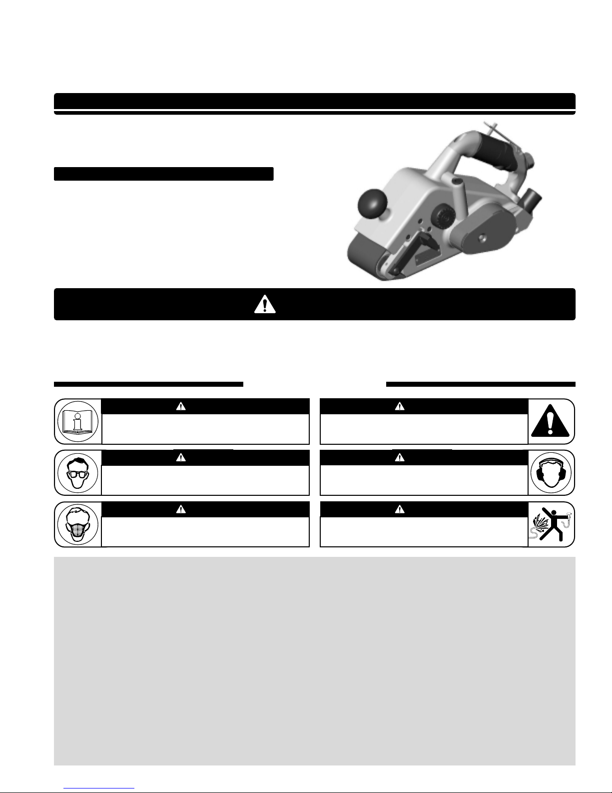
Tool Intent: 3" x 24" Belt Sanders are ideal for removal of materials using abrasive belt accessories.
Do Not Use Tool For Anything Other Than Its Intended Applications.
This power tool is not intended for use in potentially explosive atmospheres and is not insulated against contact with electrical power.
Training: Proper care, maintenance, and storage of your tool will maximize their performance.
• Employer's Responsibility – Provide 3" x 24" Belt Sander operators with safety instructions and training for safe use of tools and accessories.
Accessory Selection:
• Abrasive/accessory RPM (speed) rating MUST be approved for AT LEAST the tool RPM rating.
• Before mounting an accessory, visually inspect for defects. Do not use defective accessories.
• Use only recommended accessories. See back page of manual and Dynabrade literature.
• Follow tool specifications before choosing size and type of accessory.
• Only use recommended fittings and air line sizes. Air supply hoses and air hose assemblies must have a minimum working pressure rating of 150 PSIG
(10 Bars, g) or 150 percent of the maximum pressure produced in the system, whichever is higher. (See tool Machine Specifications table.)
Parts Page Reorder No. PD05•09
Effective January, 2005
3" x 24" Belt Sander
Air Tool Manual – Safety, Operation and Maintenance
Models:
52900 – Central Vacuum
SAFETY LEGEND
G
Read and understand tool manual before
work starts to reduce risk of injury to
operator, visitors, and tool.
Eye protection must be worn at all times,
eye protection to conform to ANSI Z87.1.
Respiratory protection to be used when exposed to
contaminants that exceed the applicable threshold
limit values required by law.
Practice safety requirements.Work aler t,
have proper attire, and do not operate tools under
the influence of alcohol or drugs.
Ear protection to be worn when exposure to sound,
exceeds the limits of applicable Federal, State or
local statues, ordinances and/or regulations.
Air line hazard, pressurized supply lines and flexible
hoses can cause serious injury.Do not use damaged,
frayed or deteriorated air hoses and fittings.
Read and understand this tool manual before operating your air tool.Follow all safety rules for the protection of operating personnel
as well as adjacent areas. Always operate, inspect and maintain this tool in accordance with the American National Safety Institute
(ANSI) Safety Code for Portable Air Tools – B186.1. For additional safety information,refer to Safety Requirements for the Use, Care
and Protection of Abrasive Wheels – ANSI B7.1, Code of Federal Regulation – CFR 29 Part 1910, European Committee for Standards
(EN) Hand Held Non-Electric Power Tools – Safety Requirements and applicable State and Local Regulations.
SAVE THIS DOCUMENT, EDUCATE ALL PERSONNEL
Maximum Surface Feet per Minute (SFPM) 1700 / (SMPM) 516
WARNIN
WARNING
WARNING
WARNING
WARNING
WARNING
WARNING
Page 2
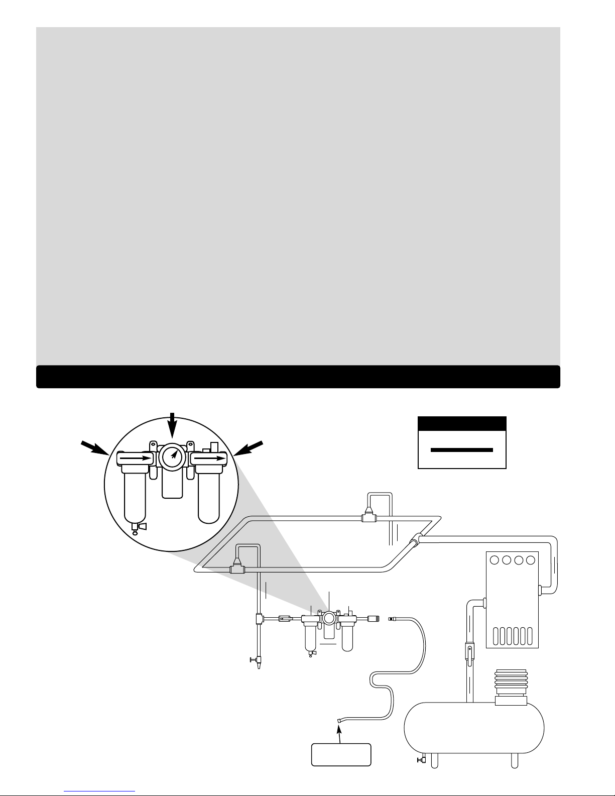
To Tool Station
Closed Loop Pipe System
(Sloped in the direction of air flow)
Ball
Valve
Ball
Valve
Filter
Regulator
Lubricator
Air Flow
Drain
Valve
Drain
Valve
Air Tool
Air Compressor
and Receiver
Drain Valve
Air Hose
90 PSIG MAX
(6.2 Bar)
Air Flow
Refrigerated
Air Dryer
2
Filter
Regulator
Lubricator
90 PSIG
(6.2 Bar)
OPERATING INSTRUCTIONS
Warning: Always wear eye protection. Operator of tool is responsible for following: accepted eye, face, respiratory, hearing and body protection.
Caution: Hand, wrist and arm injury may result from repetitive work, motion and overexposure to vibration.
• Keep hand and clothing away from working end of the air tool.
Operation: Be sure that any loose clothing, hair and all jewelry is properly restrained.
• Secure inlet bushing on air tool with a wrench before attempting to install the air fitting to avoid damaging housing assembly.
• BEFORE MOUNTING AN ACCESSORY, after all tool repairs and whenever a 3" x 24" Belt Sander is issued for use, check tool RPM (speed) with
tachometer with air pressure set at 90 PSIG while the tool is running. If tool is operating at a higher speed than the RPM marked on the tool housing, or
operating improperly, the tool must be serviced and corrected before use.
Caution:Tool RPM must never exceed abrasive/accessory RPM rating. Check accessory manufacturer for details on maximum operating speed or special
mounting instructions.
• With power source connected at the air tool relieve hose of air pressure and disconnect tool from air supply when changing recommended accessories.
• Connect air tool to power source. Be careful NOT to depress throttle lever in the process.
Do not expose air tool to inlet pressure above 90 PSIG or (6.2 Bars).
Caution:After installing the accessory, before testing or use and/or after reassembling tool, the 3" x 24" Belt Sander must be started at a reduced
speed to check for good balance. Gradually increase tool speed. DO NOT USE if tool vibration is excessive. Correct cause, and retest to
insure safe operation.
• Only use abrasive sanding belts when properly secured to the drive and idler wheels of the air sander.
• Make sure that work area is uncluttered, and visitors are at a safe range from the tools and debris. Potentially explosive atmospheres can be caused
by dust and fumes resulting from sanding or grinding. Always use dust extraction or suppression systems which are suitable for the material
being processed.
• Proceed with caution in unfamiliar surroundings. Hidden hazards may exist, such as electricity or other utility lines.
• Air tools are not intended for use in explosive atmospheres and are not insulated for contact with electric power sources.
• Use a vise or clamping device to hold work piece firmly in place.
• Work may generate hazardous dust.
• Do not apply excessive force on tool or apply “rough” treatment to it.
• Always work with a firm footing, posture and proper lighting.
• Ensure that sparks and debris resulting from work do not create a hazard.
• This tool is side exhaust. Exhaust may contain lubricants, vane material, bearing grease, and other materials flushed thru the tool.
Report to your supervisor any condition of the tool, accessories, or operation you consider unsafe.
Air System
1 DROP/MIN.
20 SCFM
LUBRICATOR SETTING
• Dynabrade Air Power Tools are designed to
operate at 90 PSIG (6.2 Bar/620 kPa) maximum
air pressure at the tool inlet, when the tool is
running. Use recommended regulator to control
air pressure.
• Ideally the air supply should be free from moisture.
Incorporating a refrigerated air dryer after the
compressor and drain valves at each tool station
(as shown) further reduces moisture from
condensation in the air supply.
➤
➤
➤
➤
➤
➤
Page 3

Model Motor Drive Wheel Belt Size Sound Maximum Air Flow Hose Air Inlet Max. SFPM Weight Length Height
Number HP (W) RPM Inch Level CFM/SCFM (LPM) I.D. Size Thread SMPM Pound (kg) Inch (mm) Inch (mm)
52900 1.3 (971) 2,700 3 x 24 88 dB(A) 8/50 (1,416) 1/2" or 15mm 3/8" NPT 1700 (516) 12.5 (5.7) 13-1/4 (337) 7-1/8 (181)
Additional Specifications: Air Pressure 90 PSIG (6.2 Bar)
Maintenance Instructions
Important: Apreventative maintenance program is recommended whenever portable power tools are used. The program should include inspection of air
supply lines, air line pressure, proper lubrication and repair of tools. Refer to ANSI B186.1 for additional maintenance information.
• Use only genuine Dynabrade replacement parts to insure quality. To order replacement parts, specify Model#, Serial# and RPM of your air tool.
• It is strongly recommended that all Dynabrade rotary vane air tools be used with a Filter-Regulator-Lubricator to minimize the possibility of misuse due
to unclean air, wet air or insufficient lubrication. Dynabrade recommends the following: 11405 Air Filter-Regulator-Lubricator (FRL) – Provides accurate
air pressure regulation and two stage filtration of water contaminants. Operates 40 SCFM @ 100 PSIG with 3/8" NPT female ports.
• Apply 3 plunges of 95542 Grease through grease fitting located on side of angle head with 95541 Grease Gun after every 100 Hours of use.
• Dynabrade recommends one drop of air lube per minute for each 20 SCFM (example: if the tool specification states 40 SCFM, set the drip rate on the
filter-lubricator to 2 drops per minute). Dynabrade Air Lube (P/N 95842: 1 pt 473 ml) is recommended.
Routine Preventative Maintenance:
• Check the free speed of 3" x 24" Belt Sander by using a tachometer on regular basis.
• Mineral spirits are recommended when cleaning the tool and parts. Do not clean tool or parts with any solvents or oils containing acids, esters,
ketones, chlorinated hydrocarbons or nitro carbons.
• DO NOT
clean or maintain tools with chemicals that have a low flash point (example: WD-40®).
• A Motor Tune-Up Kit (P/N 98223) is available which includes high wear and medium wear motor parts.
• Air tool labels must be kept legible at all times, if not, reorder label(s) and replace. User is responsible for maintaining specification information i.e.:
Model #, S/N, and RPM. (See Assembly Breakdown)
• Blow air supply hose out prior to initial use.
• Visually inspect air hoses and fittings for frays, visible damage and signs of deterioration. Replace damaged or worn components.
• Refer to Dynabrade's Warning/Safety Operating Instructions Tag (Reorder No. 95903) for safety information.
After maintenance is performed on tool, add a few drops of Dynabrade Air Lube (P/N 95842) to the air line and start the tool a few times to lubricate air motor.
Check for excessive tool vibration.
Handling and Storage:
• Use of tool rests, hangers and/or balancers is recommended.
• Protect tool inlet from debris (see Notice below).
• DO
NOT carry tool by air hose, or near the tool throttle lever.
• Protect abrasive accessories from exposure to water, solvents, high humidity, freezing temperature and extreme temperature changes.
• Store accessories in protective racks or compartments to prevent damage.
Notice
All Dynabrade motors use the highest quality parts and materials available and are machined to exacting tolerances. The failure of quality pneumatic motors
can most often be traced to an unclean air supply or the lack of lubrication. Air pressure easily forces dirt or water contained in the air supply into motor
bearings causing early failure. It often scores the cylinder walls and the rotor blades resulting in limited efficiency and power. Our warranty obligation is
contingent upon proper use of our tools and cannot apply to equipment which has been subjected to misuse such as unclean air, wet air or a lack of
lubrication during the use of this tool.
One Y ear Warranty
Following the reasonable assumption that any inherent defect which might prevail in a product will become apparent to the user within one year from the
date of purchase, all equipment of our manufacture is warranted against defects in workmanship and materials under normal use and service. We shall
repair or replace at our factory, any equipment or part thereof which shall, within one year after delivery to the original purchaser, indicate upon our
examination to have been defective. Our obligation is contingent upon proper use of Dynabrade tools in accordance with factory recommendations,
instructions and safety practices. It shall not apply to equipment which has been subject to misuse, negligence, accident or tampering in any way so as to
affect its normal performance. Normally wearable parts such as bearings, contact wheels, rotor blades, etc., are not covered under this warranty.
Machine Specifications
3
Page 4

82
81
80
4
3
42
27
1
29
21
41
40
38
1
32
34
31
33
SEE DETAIL B
35
4
3
50
49
48
36
47
46
45
3
4
SEE DETAIL A
44
39
37
43
30
28
14
13
12
79
10
9
8
7
6
5
3
4
2
51
52
1
26
25
23
24
22
27
17
18
21
20
19
4
3
15
16
DETAIL A
60
59
55
56
53
58
57
11
54
83
78
14
75
21
76
65
69
67
71
73
77
74
70
68
72
61
64
14
62
DETAIL B
66
95
94
93
91
92
90
89
88
DETAIL C
SEE DETAIL C
87
85 84
86
3" x 24" Belt Sander
Complete Assembly
1 96030 Screw (7)
2 31636 Cover Plate
3 01790 Screw (17)
4 01791 Lock Washer (17)
5 31637 Motor Cover
6 31638 Gasket
7 31635 1.3Hp Motor Assembly
8 07158 Spacer
9 97140 Screw
10 31639 Idler Wheel Assembly
11 95446 Washer (3)
12 31640 Drive Wheel
13 31641 Snap Ring
14 02695 Bearing (3)
15 07136 Grip
16 01089 Safety Lever
17 51937 Inlet Bushing
18 07142 Bushing
19 01017 Pin
20 31651 Handle
21 95928 Fitting (4)
22 07168 Valve Stem Assembly
23 31642 Spring
24 07147 Plug
25 07146 Packing
26 31677 Tubing
27 95523 O-Ring (3)
28 56076 Plug (2)
29 31643 Knob
30 97109 Screw
31 31671 Mounting Plate
32 31672 Valve Assembly
33 31673 Check Valve
34 95073 Right Angle Fitting
35 31650 Housing
36 02614 Bearing
37 95555 Bearing
38 31655 Wheel Drive Shaft
39 31654 Key
40 31657 Gear
41 95159 Snap Ring
42 01775 Pin
43 31649 Central Vac Adapter
44 31658 Gasket
45 31645 Timing Belt
46 31646 Belt Guard
47 31678 Screw
48 31682 Felt Muffler (2)
49 31681 Muffler Cap
50 31683 Muffler Flange
51 31647 Platen
52 31648 Platen Cover Plate
53 31659 Shaft
54 31653 Key
55 31656 Pinion
56 30356 Bearing
57 31664 Cover Plate
58 31660 Gear
59 31661 Snap Ring
60 01041 Grease Fitting
61 31675 Snap Ring
62 31666 Front Wheel Hub
63 31667 Spacer
64 31669 Shaft
65 97049 Bolt
66 95316 Pin
67 31668 Tension Arm
68 11040 Spring
69 31670 Tracking Bar
70 31674 Screw
71 31685 Tracking Knob
72 31662 Guide Shaft
73 97805 Air Cylinder
74 01020 O-Ring
75 31665 Guide Block
76 31663 Bearing (2)
77 95311 Screw (4)
78 31676 Tubing
Index Key
No. Part # Description
79 95572 Bearing (2)
Incld. w/31639
80 95531 Label
81 95442 Screw (2)
82 31684 Spacer
83 95146 Washer
84 31634 Timing Belt Pinion
85 31644 Washer
86 31633 Rotor Nut
87 02552 Bearing
88 01277 Shim Pack (3/pkg.)
89 31632 Front Bearing Plate
90 52467 Spacer
91 31631 Rotor
92 54972 Vane (5/pkg.)
93 54976 Cylinder (Incld. 51046)
94 54977 Rear Bearing Plate
95 02651 Bearing
No. Part # Description
Adhesive: A1= Loctite #609 A6= Loctite #380
A
3
= Loctite #242 A8= Loctite #567
Torque: N•m x 8.85 = In. - lbs.
Oil: O
1
= Air Lube Grease:
G1= Lubriplate 630 AA
O
A
T
G
KEY
A
1
A
1
O
1
A
1
A
1
G
1
G
1
A
1
A
1
A
1
A
1
A
1
G
1
A
6
A
8
A
8
O
1
9 N•m
T
9 N•m
T
17 N•m
T
9 N•m
T
9 N•m
T
9 N•m
T
9 N•m
T
9 N•m
T
Left Hand Threads
Page 5

Disassembly/Assembly Instructions for 3"X 24" Belt Sander
Important: Manufactures warranty is void if machine is disassembled before warranty expires.
The special repair tools referred to in these instructions can be purchased from Dynabrade Inc. Please refer to the exploded view of this machine
for proper part identification.
Motor Disassembly:
1. Shut the air supply and disconnect the machine from the air supply hose.
2. Release the belt tension and remove the abrasive belt.
3. Use a 2.5mm hex key to remove the 96030 Screws (2) and the 31636 Cover Plate.
4. Use a Phillips
®
screwdriver to remove the 31678 Screw and the 31646 Belt Guard.
5. Use a small thin flat blade screwdriver to remove the 31661 Snap Ring.
6. Remove the 31645Timing Belt. Important:Carefully check the condition of the timing belt, the timing belt pinion and the timing belt gear. Also, check
the condition of the related drive mechanism. Service as required.
7. Use a 5mm hex key to remove the 01790Screws (5), the 01791 Washers (5), the 31637 Motor Cover and the 31638 Motor Gasket.
8. Carefully push/pull the motor assembly out of the 31650Housing.
9. Fasten a 4
5
/8" bearing separator around the back portion of the 54976 Cylinder, (area closest to the 54977 Rear Bearing Plate).
10. Position the motor along with the attached bearing separator in the 96323Arbor Press (#2) so that the 31634 Timing Belt Pinion is pointing down.
Note: Additional blocking may be required between the separator and the table of the arbor press to allow clearance for disassembling the motor.
11. Use a short flat end press tool to push the 31631 Rotor out of the 02651 Bearing.
12. Remove the 54972 Vanes (5), the 02651 Bearing, and the 07158 Spacer.
13. Hold the rotor in a vise equipped with aluminum or bronze jaws so that the timing belt pinion is pointing up.
14. Use a non-marring strap wrench to remove the timing belt pinion by turning it clockwise. (Left Hand Thread) Remove the 31644Washer.
15. Use an adjustable open-end wrench to remove the 31633Rotor Nut by turning it clockwise. (Left Hand Thread)
16. Remove the 31632 Front Bearing Plate, the 02552 Bearing, the 01277 Shims, and the 52467 Spacer.
Motor Disassembly Complete.
Important: Clean and inspect motor parts for wear or defect before assembling.
Motor Assembly:
1. Hold the rotor in a vise equipped with aluminum or bronze jaws so that the threaded spindle is pointing up.
2. Install the 52467 Spacer onto the rotor.
3. Install the 31632 Front Bearing Plate and the 02552 Bearing onto the rotor.
4. Install the 31633 Rotor Nut hand tight by turning it counterclockwise. (Left Hand Thread)
5. Check the fit between the front of the rotor and the face of the bearing plate. The clearance should be .001"- .0015" (0.3mm – 0.4mm).
Note: A.001" (0.3mm) feeler gauge can be used to check the clearance. If the fit is too loose, remove the rotor nut and select a .001" (0.3mm) thick
shim from the 01277 Shim Pack. Place the .001" (0.3mm) shim in between the 02552 Bearing and the inside of the 31633 Front Bearing Plate. Install
these components onto the rotor and make the rotor nut hand tight to hold them in place. Check the clearance. Repeat this process as necessary until
the correct clearance is established.
6. With correct clearance established, use a 22mm crowfoot/torque wrench and tighten the 31633Rotor Nut. (Torque to 17N·m/150 in. lbs.)
7. Position the rotor in the vise equipped with aluminum of bronze jaws so that the threaded spindle is pointing up. Install the 31644Washer and
the 31634 Timing Belt Pinion. (Left Hand Thread) Tighten with a non-marring strap wrench. (Torque to 17N·m/150 in. lbs.)
8. Apply the 95842 Dynabrade Air Lube (10W/NR of equivalent) to the vanes. Install vanes with the curved side toward the center of the rotor.
9. Install the 54976 Cylinder so that the line-up pin fits into the hole in the front bearing plate.
10. Install the 54977 Rear Bearing Plate and the 02651 Bearing. Note: Use the 96239 Bearing Press Tool so that the raised center portion is positioned
against the inner race of the 02651 Bearing. Use the 96232 Arbor Press (#2) to carefully press the bearing down until it touches against the bearing seat
on the inside of the rear bearing plate. This should create a snug fit between the bearing plates and the cylinder. Note:A “snug fit” allows the cylinder to
be shifted from side to side with slight finger pressure while still trapping the cylinder so that it is not loose or sloppy between the bearing plates.
11. Apply a small amount of petroleum grease to the exposed shield of the 02552 Bearing and then install the 52467 Spacer over the timing belt pinion and
washer. Position the spacer so that it is centered on the 02552 Bearing and the grease sticks it to the bearing.
12. Carefully install the motor into the 31650 Housing using the line-up pin as a guide for positioning the motor correctly in the housing.
13. Install the 31638 Gasket, and the 31637 Motor Cover with the 01790 Screws (5), and the 01791 Washers (5). Use a 5mm hex key to fasten these
components. (Torque to 9N·m/80 in. lbs.)
14. Add several drops of the 95842Dynabrade Air Lube (10W/NR or equivalent) through the air inlet fitting, connect the machine to the air supply hose,
and turn on the air supply to test run the air motor.
15. Shut the air supply and disconnect the machine from the air supply hose.
16. If the air motor functions properly, install the 31645 Timing Belt and the 31661 Snap Ring. Carefully rotate the timing belt and gear mechanism by hand
to check for smooth operation and proper belt tracking. Important: If the air motor does not function properly, disassemble and make the necessary
adjustments. If the timing belt and the related drive mechanism does not function properly, disassemble and make the necessary adjustments.
17. Use a Phillips
®
screwdriver to install the 31678 Screw and the 31646 Belt Guard.
18. Use a 2.5mm hex key to install the 96030 Screws (2) and the 31636 Cover Plate.
19. Install the abrasive belt and apply the belt tension.
20. Add several drops of the 95842Dynabrade Air Lube (10W/NR or equivalent) through the air inlet fitting, connect the machine to the air supply hose,
and turn on the air supply.
21. With the machine off the work surface, carefully run and track the abrasive belt.
Motor Assembly Complete. Sander Assembly Complete.Please allow 30 minutes for adhesives to cure before operating tool.
Important: Motor should now be tested for proper operation at 90 PSIG. If motor does not operate properly or operates at a higher RPM than marked on the
tool, the tool should be serviced to correct the cause before use. Before operating, place 2-3 drops of Dynabrade Air Lube (P/ N 95842) directly into air inlet
with throttle lever depressed. Operate tool for 30 seconds to determine if tool is operating properly and to allow lubricating oils to properly permeate motor.
Loctite
®
is a registered trademark of Loctite Corp.
Page 6

This service chart is published as a guide to expectant life of component parts. The replacement levels are based on average tool
usage over one year. Dynabrade Inc. considers one year usage to be 1,000 hours or 50% of a man year.
Preventative Maintenance Schedule
For 3" x 24" Belt Sanders
Index Part Description Number High Wear Medium Wear Low Wear Non-Wear
# Number Required 100% 70% 30% 10%
1 96030 Screw 7 L
2 31636 Cover Plate 1 X
3 01790 Screw 17 L
4 01791 Lock Washer 17 L
5 31637 Motor Cover 1 X
6 31638 Gasket 1 T
7 31635 1.3Hp Motor Assembly 1 See Note
8 07158 Spacer 1 T
9 97140 Screw 1 X
10 31639 Idler Wheel Assembly 1 X
11 95446 Washer 3 X
12 31640 Drive Wheel 1 X
13 31641 Snap Ring 1 X
14 02695 Bearing 3 X
15 07136 Grip 1 X
16 01089 Safety Lever 1 X
17 51937 Inlet Bushing 1 X
18 07142 Bushing 1 T
19 01017 Pin 1 T
20 31651 Handle 1 X
21 95928 Fitting 4 X
22 07168 Valve Stem Assembly 1 T
23 31642 Spring 1 T
24 07147 Plug 1 X
25 07146 Packing 1 T
26 31677 Tubing 1 X
27 95523 O-Ring 3 T
28 56076 Plug 2 X
29 31643 Knob 1 X
30 97109 Screw 1 X
31 31671 Mounting Plate 1 X
32 31672 Valve Assembly 1 X
33 31673 Check Valve 1 X
34 95073 Right Angle Fitting 1 X
35 31650 Housing 1 X
36 02614 Bearing 1 X
37 95555 Bearing 1 X
38 31655 Wheel Drive Shaft 1 X
39 31654 Key 1 X
40 31657 Gear 1 X
41 95159 Snap Ring 1 X
42 01775 Pin 1 X
43 31649 Central Vac Adapter 1 X
44 31658 Gasket 1 X
45 31645 Timing Belt 1 X
46 31646 Belt Guard 1 X
47 31678 Screw 1 X
48 31682 Felt Muffler 2 T
49 31681 Muffler Cap 1 X
50 31683 Muffler Flange 1 X
51 31647 Platen 1 See Note 2
52 31648 Platen Cover Plate 1 X
53 31659 Shaft 1 X
54 31653 Key 1 X
55 31656 Pinion 1 X
56 30356 Bearing 1 X
57 31664 Cover Plate 1 X
58 31660 Gear 1 X
59 31661 Snap Ring 1 T
60 01041 Grease Fitting 1 T
61 31675 Snap Ring 1 X
62 31666 Front Wheel Hub 1 X
63 31667 Spacer 1 X
64 31669 Shaft 1 X
65 97049 Bolt 1 X
66 95316 Pin 1 X
98223 – Motor Tune-Up Kit
LEGEND
T Included in Tune-Up Kit.
X Type of wear, no other
comments apply.
L Easily lost. Care during
assembly/disassembly.
D Easily damaged during
assembly/disassembly.
R Replace each time tool is
disassembled.
Note: Please refer to page 4 and 5 of tool manual for specific part number.
Note 2: Platens are a consumable item. Platens are application sensitive, their expectant life will vary.
(continued on next page)
Page 7

DYNABRADE
®
DYNABRADE, INC., 8989 Sheridan Drive • Clarence, NY 14031-1490 • Phone: (716) 631-0100 • Fax: 716-631-2073 • International Fax: 716-631-2524
DYNABRADE EUROPE S.àr.l., Zone Artisanale • L-5485 Wormeldange—Haut, Luxembourg • Telephone: 352 76 84 94 1 • Fax: 352 76 84 95 1
©DYNABRADE, INC., 2005 PRINTED IN USA
Visit Our Web Site: www.dynabrade.com Email: Customer.Service@Dynabrade.com
Reference Contact Information
1. American National Safety Institute – ANSI 3. European Committee for Standardization
25 West 43
rd
Street Rue de Stassart 36
Forth Floor B - 1050 Brussels, Belgium
New York, NY 10036
Tel: 1 (212) 642-4900
Fax: 1 (212) 398-0023
2. Government Printing Office – GPO
Superintendent of Documents
Attn. New Orders
P.O. Box 371954
Pittsburgh, PA15250-7954
Tel: 1 (202) 512-1803
98223 Motor Tune-Up Kit
•
Includes assorted parts to
help maintain and repair motor.
Dynabrade Air Lube
• Formulated for pneumatic equipment.
• Absorbs up to 10% of its weight in water.
• Prevents rust and formation of sludge.
• Keeps pneumatic tools operating longer
with greater power and less down time.
95842: 1pt. (473 ml)
95843: 1gal. (3.8 L)
Optional Accessories
95542 Grease 10 oz.
• Multi-purpose grease for all types of
bearings, cams, gears.
• High film strength; excellent resistance to
water, steam, etc.
• Workable range 0˚ F to 300˚ F.
95541 Push-type Grease Gun
• One-hand operation.
Index Part Description Number High Wear Medium Wear Low Wear Non-Wear
# Number Required 100% 70% 30% 10%
67 31668 Tension Arm 1 X
68 11040 Spring 1 X
69 31670 Tracking Bar 1 X
70 31674 Screw 1 X
71 95218 Tracking Knob 1 X
72 31662 Guide Shaft 1 X
73 97805 Air Cylinder 1 X
74 01020 O-Ring 1 X
75 31665 Guide Block 1 X
76 31663 Bearing 2 X
77 95311 Screw 4 X
78 31676 Tubing 1 X
79 95572 Bearing 2 X
80 95531 Label 1 X
81 95442 Screw 2 X
82 31684 Spacer 1 X
83 95146 Washer 1 L
84 31634 Timing Belt Pinion 1 X
85 31644 Washer 1 X
86 31633 Rotor Nut 1 X
87 02552 Bearing 1 T
88 01277 Shim Pack (3/pkg.) 1 T
89 31632 Front Bearing Plate 1 X
90 52467 Spacer 1 X
91 31631 Rotor 1 X
92 54972 Vane (5/pkg.) 1 T
93 54976 Cylinder (Incld. 51046) 1 X
94 54977 Rear Bearing Plate 1 X
95 02651 Bearing 1 T
Preventative Maintenance Schedule (Continued)
 Loading...