

Page 1
Parts Page Reorder No. PD01•92
Effective October, 2001
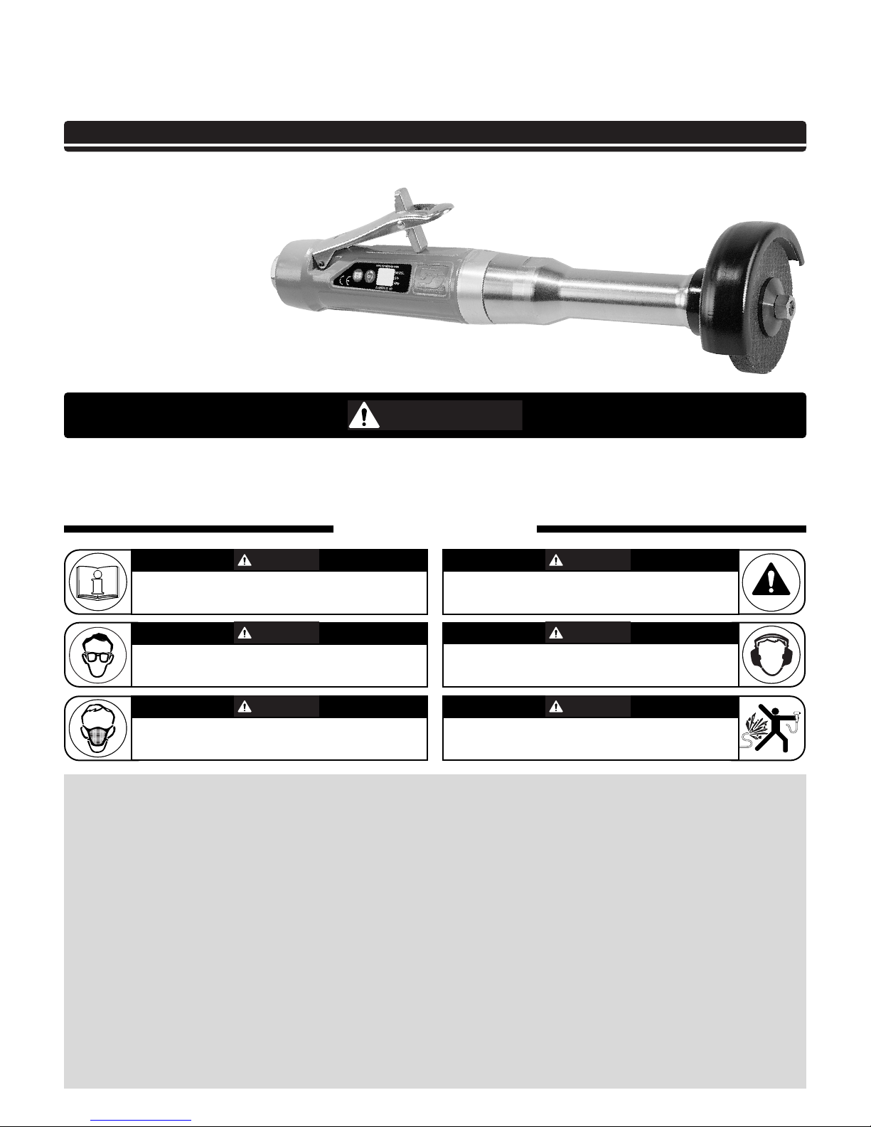
1Hp Extension Type 1 Wheel Grinders
Governor Controlled
Air Tool Manual – Safety, Operation and Maintenance
Models:
52376 – 12,000 RPM
3" Dia. x 3/8" x 1/2" Wide
Reinforced Grinding Wheel
52377 – 15,000 RPM
3" Dia. x 3/8" x 1/2" Wide
Reinforced Grinding Wheel
52378 – 18,000 RPM
3" Dia. x 3/8" x 1/2" Wide
Reinforced Grinding Wheel
52379 – 12,000 RPM
4" Dia. x 3/8" x 1/4" Wide
Reinforced Grinding Wheel
52380 – 15,000 RPM
4" Dia. x 3/8" x 1/4" Wide
Reinforced Grinding Wheel
SAFETY LEGEND
G
Read and understand tool manual to reduce risk
of injury to operator, visitors, and tool.
Eye protection must be worn at all times, eye
protection to conform to ANSI Z87.1.
Respiratory protection to be used when exposed
to contaminants that exceed the applicable
threshold limit values required by law.
Practice safety requirements. Work alert,
have proper attire, and do not operate tools under
the influence of alcohol or drugs.
Ear protection to be worn when exposure to sound,
exceeds the limits of applicable Federal, State or
local statues, ordinances and/or regulations.
Air line hazard, pressurized supply lines and flexible
hoses can cause serious injury. Do not use dam-
aged, frayed or deteriorated air hoses and fittings.
Read and understand this tool manual before operating your air tool. Follow all safety rules for the protection of operating personnel as well as adjacent areas. Always operate, inspect and maintain this tool in accordance with the American National Safety
Institute (ANSI) Safety Code for Portable Air Tools – B186.1. For additional safety information, refer to Safety Requirements for the
Use, Care and Protection of Abrasive Wheels – ANSI B7.1, Code of Federal Regulation – CFR 29 Part 1910, European Committee for
Standards (EN) Hand Held Non-Electric Power Tools – Safety Requirements and applicable State and Local Regulations.
SAFETY INSTRUCTIONS
Carefully Read all instructions before operating or servicing any Dynabrade®Abrasive Power Tool.
Products offered by Dynabrade are not to be modified, converted or otherwise altered from the original design without expressed written consent from Dynabrade, Inc.
Tool Intent: Abrasive Extension Type 1 Wheel Grinders are ideal for cleaning metal before welding, grind and smooth weld seams, remove imperfections, smooth surfaces
prior to painting or plating. Ideal for foundries, welding shops, fabrication plants, steel mills and shipyards.
Do Not Use Tool For Anything Other Than Its Intended Applications.
Training: Proper care, maintenance, and storage of your tool and abrasive wheels will maximize performance.
• Employer's Responsibility – Provide operators with safety instructions and training for safe use of tools and accessories.
Accessory Selection:
• Only use reinforced type 1 wheels.
• Abrasive/accessory RPM (speed) rating MUST be approved for AT LEAST the tool RPM rating.
• Before mounting an abrasive wheel or accessory, visually inspect for defects. Do not use defective wheels or accessories.
• Mount only recommended accessories. See back page of manual and Dynabrade catalog.
• Follow tool specifications before choosing size and type of accessory.
• Only use recommended fittings and air line sizes. Air supply hoses and air hose assemblies must have a minimum working pressure rating of 150 PSIG (10 bars, g) or 150
percent of the maximum pressure produced in the system, whichever is higher. (See tool Machine Specifications table.)
OPERATING INSTRUCTIONS
Warning: Always wear eye protection. Operator of tool is responsible for following: accepted eye, face, respiratory, hearing and body protection.
Always use wheel guard. Make sure it is positioned to best protect the operator and make sure it is securely fastened. Wheel guards that have been subject to a
wheel breaking must be replaced.
(Continued on next page)
SAVE THIS DOCUMENT, EDUCATE ALL PERSONNEL
WARNIN
WARNING
WARNING
WARNING
WARNING
WARNING
WARNING
Page 2
To Tool Station
Closed Loop Pipe System
(Sloped in the direction of air flow)
Ball
Valve
Ball
Valve
Filter
Coupler
Regulator
Lubricator
Air Flow
Drain
Valve
Drain
Valve
Air Tool
Air Compressor
and Receiver
Drain Valve
Air Hose
90 PSIG MAX
(6.2 Bar)
Air Flow
Refrigerated
Air Dryer
2
Filter
Regulator
Lubricator
90 PSIG
(6.2 Bar)
OPERATING INSTRUCTIONS (continued)
Caution: Hand, wrist and arm injury may result from repetitive work, motion and overexposure to vibration.
• Keep hand and clothing away from working end of the air tool.
Operation: Be sure that any loose clothing, hair and all jewelry is properly restrained.
• Secure inlet bushing on air tool with a wrench before attempting to install the air fitting to avoid damaging housing assembly.
• Check tool RPM (speed) with tachometer with air pressure set at 90 PSIG while the tool is running. If tool is operating at a higher speed than the RPM marked on the tool
housing, or operating improperly, the tool must be serviced and corrected before use.
Caution: Tool RPM must never exceed abrasive/accessory RPM rating. Check accessory manufacturer for details on maximum operating speed or special
mounting instructions.
• With power source disconnected from air tool, mount type 1 wheel onto spindle. See diagram below for typical mounting assembly.
• Follow recommended procedure from the manufacturer.
• Connect air tool to power source. Be careful NOT to depress throttle lever in the process. Do not expose air tool to inlet pressure above 90 PSIG or (6.2 Bars).
Caution: After installing the accessory, before starting the grinder with an abrasive wheel, it should be tested in an enclosed protective area. The operator must check to make
sure that no one is in the unguarded plane of the wheel rotation. Increase the speed of the tool gradually. The wheel must be run at free speed for at least one
minute before applying the wheel to work. During this time, check the tool for excessive vibration and noise. The cause of unusual vibration and noise must be
determined and corrected before use. DO NOT USE if tool vibration is excessive. Correct cause, and retest to insure safe operation.
• Make sure that work area is uncluttered, and visitors are at a safe range from the tools and debris.
• Use a vise or clamping device to hold work piece firmly in place.
• Do not apply excessive force on tool or apply “rough” treatment to it.
• Always work with a firm footing, posture and proper lighting.
Report to your supervisor any condition of the tool, accessories, or operation you consider unsafe.
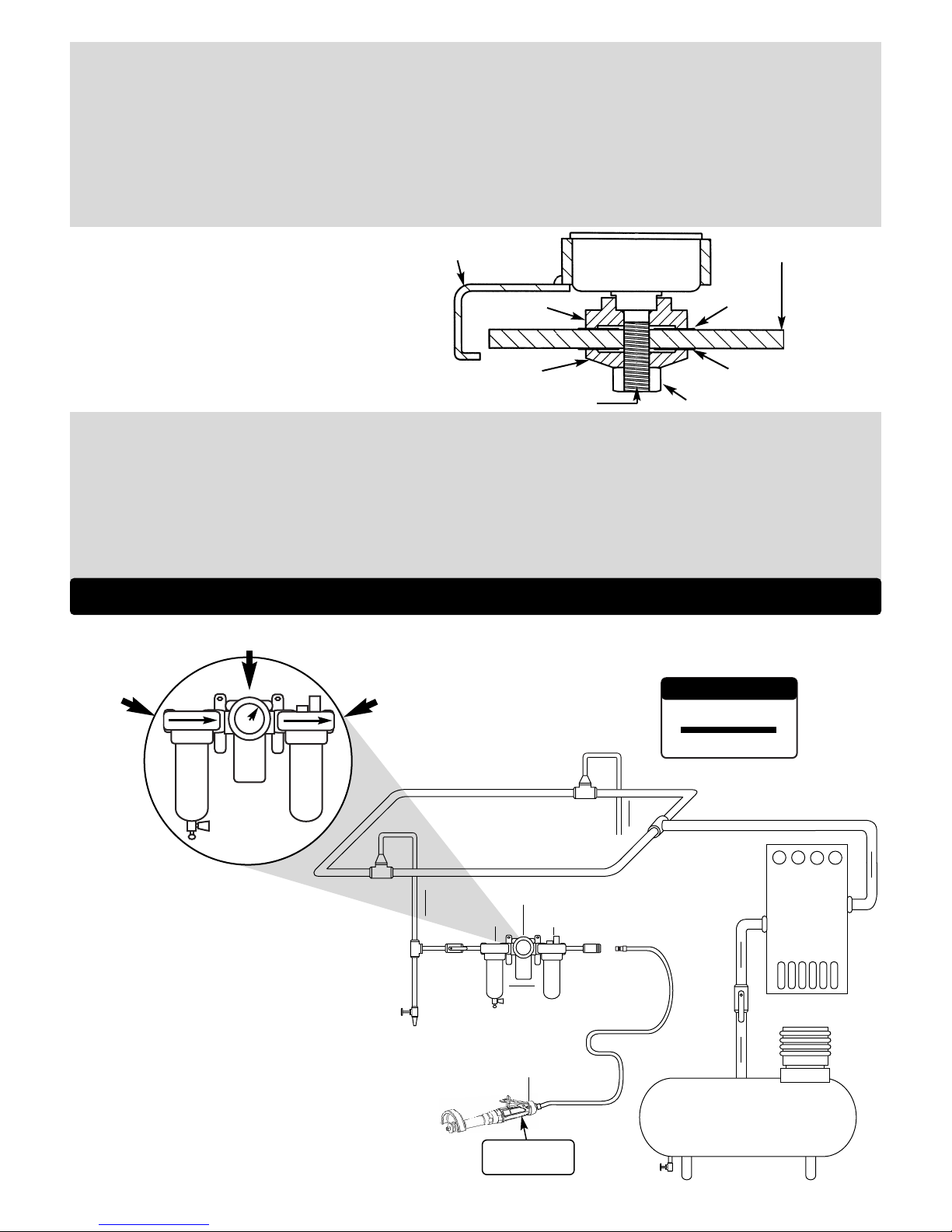
Air System
1 DROP/MIN.
10 SCFM
LUBRICATOR SETTING
• Dynabrade Air Power Tools are designed to
operate at 90 PSIG (6.2 Bar/620 kPa) maximum
air pressure at the tool inlet, when the tool is
running. Use recommended regulator to control
air pressure.
• Ideally the air supply should be free from moisture.
Incorporating a refrigerated air dryer after the
compressor and drain valves at each tool station
(as shown) further reduces moisture from
condensation in the air supply.
➤
➤
➤
➤
➤
➤
TYPE 1 WHEEL MOUNTING
Typical Mounting for Type 1 Wheels
Safety Guard Reinforced Type 1 Wheel
Outer Flange
Spindle Adapter
Blotter
Blotter
Spindle Nut
Driving Flange
• Blotters must cover at least the flange bearing surface as shown.
• A blotter (compressible washer) shall always be used between each
flange and the abrasive wheel surface to ensure uniform distribution
of flange pressure.
• Blotters shall cover the entire flange contact area.
• New blotters shall be used each time a wheel is mounted unless blotters
are affixed to the wheel by the grinding wheel manufacturer.
Page 3

Maintenance Instructions
Important: A Preventative Maintenance Program is recommended whenever portable power tools are used.
• Use only genuine Dynabrade replacement parts to insure quality. To order replacement parts, specify Model#, Serial# and RPM of your air tool.
• All Dynabrade Rotary Vane air tools must be used with a Filter-Regulator-Lubricator to maintain all warranties. Dynabrade recommends the following:
11411 Air Filter-Regulator-Lubricator (FRL) – Provides accurate air pressure regulation and two stage filtration of water contaminants. Operates 55
SCFM/1,558 LPM @ 90 PSIG with 1/2" NPT female ports.
• Dynabrade recommends one drop of air lube per minute for each 10 SCFM (example: if the tool specification states 40 SCFM, set the drip rate on the
filter-lubricator to 4 drops per minute). Dynabrade Air Lube (P/N 95842: 1 pt 473 ml) is recommended.
Routine Preventative Maintenance: Check free speed of grinder using a tachometer. This governor controlled grinder should be speed checked every 20
hours of use or weekly, whichever occurs more frequently.
• DO NOT disassemble the governor for any reason. Reorder correct speed – governor assembly (See Assembly Breakdown) and recheck free speed of
tool with a tachometer.
• Mineral spirits are recommended when cleaning the tool and parts. Do not clean tool or parts with any solvents or oils containing acids, esters,
ketones, chlorinated hydrocarbons or nitro carbons.
• DO NOT
clean or maintain tools with chemicals that have a low flash point (example: WD-40®).
• A Motor Tune-Up Kit (P/N 96532) is available which includes high wear and medium wear motor parts.
• Air tool labels must be kept legible at all times, if not, reorder label(s) and replace. (See Assembly Breakdown)
• Blow air supply hose out prior to initial use.
• DO
NOT carry tool by air hose or near the tool throttle lever.
• Visually inspect air hoses and fittings for frays, visible damage and signs of deterioration. Replace damaged or worn components.
• Refer to Dynabrade's Warning/Safety Operating Instructions Tag (Reorder No. 95903) for safety information.
After maintenance is performed on tool, add a few drops of Dynabrade Air Lube (P/N 95842) to the air line and start the tool a few times to lubricate air motor.
Check for excessive tool vibration.
Handling and Storage:
• Use of tool rests, hangers and/or balancers is recommended.
• Protect tool inlet from debris (see Notice below).
• DO
NOT carry tool by air hose or near the tool throttle lever.
• Protect type 1 grinding wheels from exposure to water, solvents, high humidity, freezing temperatures and extreme temperature changes.
• DO
NOT USE type 1 grinding wheels that have been dropped or show signs of cracks, nick or other defects.
• Store accessories in protective racks or compartments to prevent damage.
Machine Specifications
(PD01•92)
3
Notice
All Dynabrade motors use the highest quality parts and metals available and are machined to exacting tolerances. The failure of quality pneumatic motors
can most often be traced to an unclean air supply or the lack of lubrication. Air pressure easily forces dirt or water contained in the air supply into motor
bearings causing early failure. It often scores the cylinder walls and the rotor blades resulting in limited efficiency and power. Our warranty obligation is
contingent upon proper use of our tools and cannot apply to equipment which has been subjected to misuse such as unclean air, wet air or a lack of
lubrication during the use of this tool.
One Year Warranty
Following the reasonable assumption that any inherent defect which might prevail in a product will become apparent to the user within one year from the
date of purchase, all equipment of our manufacture is warranted against defects in workmanship and materials under normal use and service. We shall
repair or replace at our factory, any equipment or part thereof which shall, within one year after delivery to the original purchaser, indicate upon our
examination to have been defective. Our obligation is contingent upon proper use of Dynabrade tools in accordance with factory recommendations,
instructions and safety practices. It shall not apply to equipment which has been subject to misuse, negligence, accident or tampering in any way so as to
affect its normal performance. Normally wearable parts such as bearings, contact wheels, rotor blades, etc., are not covered under this warranty.
Model Motor Motor Sound Maximum Air Flow Air Pressure Spindle Weight Length Height
Number HP (W) RPM Level CFM/SCFM (LPM) PSIG (Bars) Thread Pound (kg) Inch (mm) Inch (mm)
52376 1.0 (744) 12,000 82 dB(A) 5/38 (1,076) 90 (6.2) 3/8"-24 male 3.9 (1.8) 14-1/4 (362) 3-1/2 (89)
52377 1.0 (744) 15,000 83 dB(A) 5/39 (1,104) 90 (6.2) 3/8"-24 male 3.9 (1.8) 14-1/4 (362) 3-1/2 (89)
52378 1.0 (744) 18,000 84 dB(A) 6/40 (1,133) 90 (6.2) 3/8"-24 male 3.9 (1.8) 14-1/4 (362) 3-1/2 (89)
52379 1.0 (744) 12,000 82 dB(A) 5/38 (1,076) 90 (6.2) 3/8"-24 male 3.9 (1.8) 14-1/4 (362) 4-1/2 (113)
52380 1.0 (744) 15,000 83 dB(A) 5/39 (1,104) 90 (6.2) 3/8"-24 male 3.9 (1.8) 14-1/4 (362) 4-1/2 (113)
Additional Specifications: Air Inlet Thread 3/8" NPT • Hose I.D. Size 3/8" (10 mm) • Air Flow Rate Based At Max HP. • Air Pressure 90 PSIG Max
Page 4

4
1 96511 Hex Nut
2 51964 Front Flange
3 51963 Rear Flange
4 51983 3" Guard
51984 4" Guard
5 53616 3" Spindle Adapter
53615 4" Spindle Adapter
6 96512 Retainer Ring
7 51956 Felt Seal
8 01007 Bearing (2)
9 51955 Spindle Extension
10 51952 Handle Extension
11 54520 Bearing (2)
12 51982 Spacer
13 51935 Coupling (2)
14 51936 Insert Coupling
15 96498 Wave Spring
16 95438 O-Ring
17 53620 Adapter
18 51951 Shim Pack
19 51922 Front Bearing Plate
20 96441 Pin (2)
21 51927 Spacer
22 51921 Rotor
23 51926 Blade (4/Pkg.)
24 51925 Cylinder
25 51923 Rear Bearing Plate
26 02057 Bearing
27 96445 Pin (2)
28 51924 Gasket
29 Governor Assembly
51930 12,000 RPM Models
51931 15,000 RPM Models
51932 18,000 RPM Models
30 All Housings Include:
Warning & Specification Labels
53723 Housing – Model 52376
53724 Housing – Model 52377
53725 Housing – Model 52378
52726 Housing – Model 52379
52727 Housing – Model 52380
31 96444 Pin
32 51949 Safety Lever Assembly
33 51946 Valve Stem Assembly
(Incl. 96443 O-Ring)
34 51945 Valve Seat
35 51942 Baffle
36 51941 Spring
37 51944 Tip Valve
38 51943 Spring
39 96442 O-Ring
40 51940 Spacer
41 51939 Silencer Ring
42 51937 Inlet Bushing
(Incl. 2 – 51938 Screens)
Index Key
No. Part # Description
43 00001248 Warning Label
44 00001181 Specification Label
Label Key
No. Part # Description
Adhesive: A8= Loctite #567
A10= Loctite #243
Torque: N•m x 8.85 = In. - lbs.
Grease: G
1
= Lubriplate 630 AA
Oil: O
1
= Air Lube
O
A
T
G
KEY
35 N•m
T
1 Hp Extension Type 1 Wheel Grinder
Complete Assembly Breakdown
4
19
20
18
11
17
11
12
9
8
7
4
1
6
3
2
14
15
16
21
22
23
24
20
36
37
38
39
40
41
25
26
27
28
29
44
31
43
33
34
35
32
30
O
1
A
10
A
8
A
10
42
2 N•m
A
10
T
17 N•m
T
35 N•m
T
17 N•m
T
17 N•m
T
10
13
5
13
Page 5

Disassembly Instructions - 1 Hp Extension Type 1 Wheel Grinder
Important: Manufacturer’s warranty is void if tool is disassembled before warranty expires.
Disconnect tool from power source before tool repair.
Motor Disassembly:
1. Remove 96511 Hex Nut and slide off 51964 Flange Washer, abrasive wheel, and 51963 Backup Flange.
2. Remove wheel guard assembly.
3. Secure front end of housing in a soft (aluminum or bronze jaw) vise, align the vise jaws with machined flat on the silver ring.
4. Apply wrench at wrench flats on 51952 Extension Handle and remove from housing.
5. Slide 51982 Bearing Spacer and spindle assembly through rear of 51952 Extension Handle.
6. Remove 96512 Retaining Ring from front of extension handle and remove 51956 Felt Seal.
7. Secure 51955 Spindle at wrench flats, and remove spindle adapter and 51935 Coupling.
8. Secure 01007 Bearing and press 51955 Spindle through both 01007 Bearings.
9. Secure 54520 Bearing and press 51955 Spindle through 54520 Bearing.
10. Remove 96498 Wave Spring from housing assembly.
11. Pull motor assembly from housing assembly, and remove 53620 Motor Adapter with 95438 O-Ring.
12. Remove governor assembly by using a slotted screw driver. (LEFT HAND thread)
13. Secure 51925 Cylinder and place a 1/8" (3 mm) drift pin to the base of the internal thread and press the 51921 Rotor from the 02057 Rear Bearing.
14. Slide 02057 Rear Bearing from 51923 Rear Bearing Plate.
15. Remove 51925 Cylinder and 51926 Blades.
16. Secure 51921 Rotor in a soft (aluminum or bronze jaw) vise and remove 51935 Coupling (twist counterclockwise).
17. Slide 51922 Front Bearing Plate and 51927 Rotor Spacer from 51921 Rotor.
18. Slide 54520 Bearing and shims from 51922 Front Bearing Plate.
Motor Disassembly Complete.
Housing Disassembly:
1. Secure housing using 51989 Repair Collar (order separately–see back cover for Optional Accessories).
2. Remove 51937 Inlet Bushing (twist counterclockwise).
3. Remove 51943 Spring, 96442 O-Ring, 51940 Spacer and 51939 Silencer Plate from 51937 Inlet Bushing.
4. Remove 51941 Spring, 51942 Baffle, 51944 Tip Valve and 51945 Valve Seat.
Disassembly Complete.
Assembly Instructions - 1 Hp Extension Type 1 Wheel Grinder
Motor Assembly:
Important: Be sure parts are clean and in good repair before assembling. Follow grease, oil and torque specifications.
1. Place 51921 Rotor into a padded vise with male thread facing upwards.
2. Slip 51927 Rotor Spacer over rotor shaft and down against rotor body face.
3. Press 96441 Coiled Pin into 51922 Front Bearing Plate. Make certain, coiled pin does not protrude beyond internal bearing surface.
4. Place a .002" Shim into the base of 51922 Front Bearing Plate as an initial spacing and slide 54520 Bearing to the front plate base.
Note: 51951 Shim Pack contains .001" and .002" shims.
5. Slip bearing/bearing plate assembly onto rotor, torque 51935 Coupling onto rotor shaft to 17 N•m (150 lbs.-in.).
6. Check clearance between rotor and front bearing plate by using a .001" feeler gauge. Clearance should be between .001" - .0015". Adjust clearance
by repeating steps 4 and 5 with different shims if necessary.
7. Once proper rotor gap clearance is achieved, install well lubricated 51926 Blades (4) into rotor slots. Dynabrade recommends lubricating blades
with 95842 Air Lube.
Important: Make certain beveled edge of blade follows rotor outside diameter.
8. Install 51925 Cylinder over rotor and front plate raised boss. Align coiled pin on front plate to cylinder slot.
9. Press 96441 Coiled Pin into blind hole on 51923 Rear Bearing Plate. Press (2) 96445 Coiled Pins into the back side of rear bearing plate.
10. Peel backing off 51924 Gasket and align it firmly in place onto 51923 Rear Bearing Plate.
11. Place 51923 Rear Bearing Plate over rotor mandrel and insert raised boss on rear bearing plate into cylinder diameter, while inserting short coiled pin into
cylinder slot. Be sure inlet slot on rear bearing plate line up with inlet slot on cylinder. Flip cylinder end to end and repeat steps 8 & 9 for correct assembly.
12. Press 02057 Bearing onto rotor and into 51923 Rear Bearing Plate hole until it is seated.
Important: While pressing 02057 Bearing, make certain to contact inner race of bearing. Cylinder must fit snug between bearing plates. If too tight,
rotor will not turn freely. Rotor must be lightly tapped at press fit end until rotor spins freely, maintain a snug fit. A loose fit will not achieve the proper
preload on motor bearings.
13. Add one drop of Loctite
®
243 (or equiv.) to governor assembly male thread and screw governor assembly into place (LEFT HAND thread) with a slotted
screw head. Torque to 2 N•m (18 lbs.-in.).
(Continued on next page)
Page 6

Assembly Instructions -
(Continued)
Important: Manufacturer’s warranty is void if tool is disassembled before warranty expires.
Please refer to parts breakdown for part identification.
14. Install motor assembly into housing, making sure motor drops all the way into housing.
Note: Align both 96445 Coiled Pins to slots in insert and against 51924 Gasket.
15. Install 95438 O-Ring onto 53620 Adapter and slide adapter into housing and over 54520 Bearing.
16. Place 96498 Wave Washer onto 53620 Adapter.
17. Place 51936 Coupling Insert into 51935 Coupling. Make certain insert radii aligns with radii in coupling base, to correct alignment remove insert
and rotate 90˚.
18. Press one 01007 bearing on end of 51955 Extension Spindle that is further from the wrench flats, then repeat with second 01007 Bearing on same
end of spindle.
Important: While pressing 01007 Bearings, make certain to contact inner race of bearing only.
19. Press 54520 Bearing onto end of spindle that is closer to wrench to wrench flats.
Important: While pressing 54520 Bearing, make certain to contact inner race of bearing only.
20. Secure spindle and apply Loctite
®
243 (or equiv.) to external threads then torque 51935 Coupling on single bearing end to 17 N•m (150 lb.-in.).
21. On double bearing end, apply Loctite
®
243 (or equiv.) to external threads and torque spindle adapter to 17 N•m (150 lb.-in.).
22. Install 51956 Felt Seal over spindle adapter.
23. Install 96512 Retaining Ring into groove inside 51952 Extension Handle.
24. Insert spindle assembly, with spindle adapter first, into larger diameter end of 51952 Extension Handle.
25. Insert 51982 Bearing Spacer into larger diameter end of extension handle.
26. Pull 51936 Coupling Insert half way off of 51935 Coupling to assure alignment with mating coupling.
27. Apply adhesive Loctite
®
567 (or equiv.) to external threads on housing.
28. Align 51936 Coupling insert onto 51935 Coupling in extension handle.
29. Thread housing assembly onto extension handle.
30. Secure front end of housing in a padded vise, align the vise jaws with machined flat on the silver ring.
31. Apply wrench at wrench flats on 51952 Extension Handle and torque handle onto housing to 35 N•m (310 lb.-in.).
32. Install guard onto extension housing.
Motor Assembly Complete.
Housing Assembly:
1. Secure housing using 51989 Repair Collar (see back cover for Optional Accessories) with wheel adapter facing downward.
2. Install 51945 Valve Seat by aligning 3 male prongs with three deep slots on insert. Make certain valve seat is pressed flat against base of pocket.
Note: Add a few drops of Dynabrade Air Lube (P/N 95842) to pocket walls before inserting 51945 Valve Seal.
3. Install 51944 Tip Valve as shown.
4. Slide 51942 Baffle into housing long end in first, and place 51941 Spring into shallow wall end of baffle.
5. Pre-assemble 51937 Inlet Bushing by sliding 51939 Silencer Plate, 51940 Spacer over male thread and set 96442 O-Ring into groove at the base of
thread. Slide 51943 Spring into bushing and up to the two 51938 Screens.
6. Apply one drop of Loctite
®
243 (or equiv.) to 51937 Inlet Bushing thread.
7. Align small inside diameter of 51943 Spring to cone point on 51944 Tip Valve and thread 51937 Inlet Bushing and sub-assembly into place. Torque
bushing to 35 N•m (310 lb.-in.).
8. Slide 96443 O-Ring onto 51946 Valve Stem and slide sub-assembly until o-ring passes through housing hole. Make certain valve stem assembly slides
freely after the o-ring passes through the hole.
9. Remove housing from 51989 Repair Collar and place repair collar onto the bench top with the part number identifier against the bench. Align the
throttle lever holes to housing pin hole and rest the housing and throttle lever onto the legs of the repair collar. Press 96444 Coiled Pin into lever hole
and center into housing.
Tool Assembly Complete. Please allow 30 minutes for adhesives to cure before operating tool.
Important: Motor should now be tested for proper operation at 90 PSIG max. If tool operates at higher RPM than marked on the tool of if vibration levels
seem abnormal, the tool should be serviced to correct the cause before use.
Loctite
®
is a registered trademark of Loctite Corp.
1. Slide 51963 Backup Flange onto spindle adapter, align slot on backup flange with machined flats on spindle adapter.
2. Slide abrasive wheel with blotters and 51694 flange washer onto spindle adapter, and install 96511 Hex Nut.
Caution: Tighten hex nut only enough to prevent the abrasive wheel from spinning under working conditions. Over tightening the hex nut can cause
damage to the abrasive wheel and/or flanges.
Important: Tool assembly should now be tested for proper operation at 90 PSIG max. If tool operates at higher RPM than marked on the tool of if vibration
levels seem abnormal, the tool should be serviced to correct the cause before use.
6
Page 7

This service chart is published as a guide to expectant life of component parts. The replacement levels are based on average
tool usage over one year. Dynabrade Inc. considers one year usage to be 1,000 hours or 50% of a man year. Parts included in
motor tune-up kit are identified by High Wear and Medium Wear items.
Preventative Maintenance Schedule
For All 1Hp Extension Type 1 Wheel Grinders
LEGEND
X Type of wear, no other
comments apply.
L Easily lost. Care during
assembly/disassembly.
D Easily damaged during
assembly/disassembly.
R1 Replace each time tool is
disassembled.
R2 Replace each second
time tool is disassembled.
7
96532 – 1 Hp. Motor Tune-Up Kit
•
Tune-Up Kit includes high wear
and medium wear motor parts.
Parts Common to all Models:
Note: Please refer to page 4 of tool manual for specific part number.
Index Part Description Number High Wear Medium Wear Low Wear Non-Wear
# Number Required 100% 70% 30% 10%
1 96511 Hex Nut 1 X
2 51964 Front Flange 1 X
3 51963 Rear Flange 1 X
4 51983 3" Guard 1 X
51984 4" Guard 1 X
5 53616 3" Spindle Adapter 1 X
53615 4" Spindle Adapter 1 X
6 96512 Retainer Ring 1 L
7 51956 Felt Seal 1 X
8 01007 Bearing 2 X
9 51955 Spindle Extension 1 X
10 51952 Handle Extension 1 X
1
1 54520 Bearing 2 X
12 51982 Spacer 1 X
13 51935 Coupling 2 X
14 51936 Insert Coupling 1 X
15 96498 Wave Spring 1 X
16 95438 O-Ring 1 L
17 53620 Adapter 1 X
18 51951 Shim Pack 1 L
19 51922 Front Bearing Plate 1 X
20 96441 Pin 2 X
21
51927 Spacer 1 X
22 51921 Rotor 1 X
23 51926 Blade (4/pkg.) 1 X
24 51925 Cylinder 1 X
25 51923 Rear Bearing Plate 1 X
26 02057 Bearing 1 X
27 96445 Pin 2 X
28 51924 Gasket 1 X
29 51930 Governor 12,000 RPM 1 X
51931 Governor 15,000 RPM 1 X
51932 Governor 18,000 RPM 1 X
30
See Note Housing 1 X
31
96444 Pin 1 L
32 51949 Safety Lever Assembly 1 X
33 51946 Valve Stem Assembly 1 X
34 51945 Valve Seat 1 X
35 51942 Baffle 1 X
36 51941 Spring 1 X
37 51944 Tip Valve 1 X
38 51943 Spring 1 X
39 96442 O-Ring 1 L
40 51940 Spacer 1 X
41
51939 Silencer Ring 1 X
42 51937 Inlet Bushing 1 X
(Incl. 2 – 51938 Screens) 1
Page 8

DYNABRADE, INC., 8989 Sheridan Drive • Clarence, NY 14031-1490 • Phone: (716) 631-0100 • Fax: 716-631-2073 • International Fax: 716-631-2524
DYNABRADE EUROPE S.àr.l., Zone Artisanale • L-5485 Wormeldange—Haut, Luxembourg • Telephone: 352 76 84 94 1 • Fax: 352 76 84 95 1
© DYNABRADE, INC., 2001 PRINTED IN USA
Visit Our Web Site: www.dynabrade.com Email: Customer.Service@Dynabrade.com
Optional Accessories
Dynaswivel
®
• Swivels 360° AT TWO PIVOT POINTS allowing the air hose to
drop directly to the floor while providing superb tool handling.
95461 – 3/8" NPT.
51989 Repair Collar
• Specially designed collar for use in vise to prevent damage
to valve body of tool during disassembly/assembly.
53621 Over Hose Assembly
• Over Hose Assembly directs exhaust
away from operator.
30335 Air Supply Hose
• 3/8 in. I.D. x 60 in. Wide air supply
hose, includes: 3/8 in. NPT male and
female threaded fittings.
96005 Male Plug
• Provides up to twice the air flow
compared to standard plug design.
• Plug has “ported” design to prevent
“starving” of the air tool.
Dynabrade Air Lube
• Formulated for pneumatic equipment.
• Absorbs up to 10% of its weight in water.
• Prevents rust and formation of sludge.
• Keeps pneumatic tools operating longer
with greater power and less down time.
95842: 1pt. (473 m)
95843: 1gal. (3.8 L)
Reference Contact Information
1. American National Safety Institute – ANSI
11 West 42
nd
Street
New York, NY 10036
Tel: 1 (212) 642-4900
2. Government Printing Office – GPO
Superintendent of Documents
Attn. New Orders
P.O. Box 371954
Pittsburgh, PA 15250-7954
Tel: 1 (202) 512-1803
3. European Committee for Standardization
Rue de Stassart 36
B - 1050 Brussels, Belgium
95262 – 14 mm open-end.
95304 – 24 mm open-end.
53690 Extension Grip
• Provides added ergonomic
comfort and control when
handling tool.
96532 Motor Tune-Up Kit
•
Includes assorted parts to help maintain
and repair motor.
01902 Drop-In Motor
•
Allows quick and easy replacement.
No motor adjustments needed.
Bearing Press Tools
• Used to install bearings.
96243: For installing 02057 Bearing.
96244: For installing 01007 & 54520 Bearings.
®
DYNABRADE
 Loading...