

Page 1
Pencil Grinder
Turbine-Driven Air Motor
SAFETY, OPERATION AND MAINTENANCE - SAVE THIS DOCUMENT, EDUCATE ALL PERSONNEL
Parts Page Reorder No. PD10•37
Effective October, 2010
Supersedes PD10•11
SAFETY INSTRUCTIONS
Carefully Read all instructions before operating or servicing any Dynabrade®Abrasive Power Tool.
Products offered by Dynabrade are not to be modified, converted or otherwise altered from the original design.
DO NOT USE tool for anything other than its intended applications.
Training: Proper care, maintenance, and storage of your air tool will maximize tools performance and reduce chance for accident.
Employer's Responsibility: Provide operators with safety instructions and training for safe use of tools and accessories.
REPORT TO YOUR SUPERVISOR ANY CONDITION OF THE TOOL, ACCESSORIES, OR OPERATION YOU CONSIDER UNSAFE.
Read and understand tool manual before
work starts to reduce risk of injury to
operator, visitors, and tool.
Eye protection must be worn
at all times, eye protection to
conform to ANSI Z87.1.
Respiratory protection to be used when
exposed to contaminants that exceed the
applicable threshold limit values required by law.
Air line hazard, pressurized supply lines and flexible
hoses can cause serious injury. Do not use damaged,
frayed or deteriorated air hoses and fittings.
WARNING
Ear protection to be worn when exposure to sound,
exceeds the limits of applicable Federal, State or local
statues, ordinances and/or regulations.
Read and understand this tool manual before operating your air tool. Follow all safety rules for the protection of operating personnel as well
as adjacent areas. Always operate, inspect and maintain this tool in accordance with the American National Standards Institute (ANSI) Safety
Code for Portable Air Tools – B186.1. For additional safety information, refer to Safety Requirements for the Use, Care and Protection of Abrasive Wheels – ANSI B7.1, Code of Federal Regulation – CFR 29 Part 1910, European Committee for Standards (EN) Hand Held Non-Electric
Power Tools – Safety Requirements and applicable State and Local Regulations.
Some dust created by sanding, grinding, drilling, and other construction activities contain chemicals known to cause cancer, birth defects
or other reproductive harm. Some examples of these chemicals are:
• Lead from lead-based paints
• Crystalline silica from bricks and cement and other masonry products
• Arsenic and chromium from chemically treated lumber
Your risk from these exposures varies, depending on how often you do this type of work. To reduce your exposure to these chemicals: work in a well
ventilated area, and work with approved safety equipment, such as those dust masks that are specially designed to filter out microscopic particles.
Practice safety requirements. Work alert,
have proper attire, and do not operate tools under
the influence of alcohol or drugs.
FIND THE MOST CURRENT OFFERING OF SUPPORT DOCUMENTS AND ACCESSORIES AT WWW.DYNABRADE.COM
Tool Intent: Pencil Grinders are ideal for light deburring, deflashing, surface preparation, cleaning and finishing using proper accessories.
CAREFULLY READ AND UNDERSTAND
PNEUMATIC TOOL SAFETY GUIDELINES (P/N 00001676) BEFORE HANDLING OR USING TOOL.
Model RPM Insert Style
51622
35,000 1/8" Central Vacuum
51623
35,000 1/8" Central Vacuum, Ext.
51624
35,000 3 mm Central Vacuum
51629
50,000 1/8" Central Vacuum
51630
50,000 1/8" Central Vacuum, Ext.
51631
50,000 3 mm Central Vacuum
51632
60,000 1/8" Central Vacuum
51633
60,000 1/8" Central Vacuum, Ext.
51634
60,000 3 mm Central Vacuum
51700
60,000 1/8" Standard
51701
60,000 3 mm Standard
51702
60,000 3/32" Standard
51703
50,000 1/8" Standard
51704
50,000 3 mm Standard
51705
50,000 3/32" Standard
51706
35,000 1/8" Standard
51707
35,000 3 mm Standard
51708
35,000 3/32" Standard
51730
50,000 1/8" Ceramic Bearing
51731
60,000 1/8" Ceramic Bearing
51732
50,000 3 mm Ceramic Bearing
51733
60,000 3 mm Ceramic Bearing
51750
60,000 1/8" Extension
51753
50,000 1/8" Extension
51756
35,000 1/8" Extension
For Serial No. 02A1000 and Higher
Model 51706
Shown
Page 2
➤
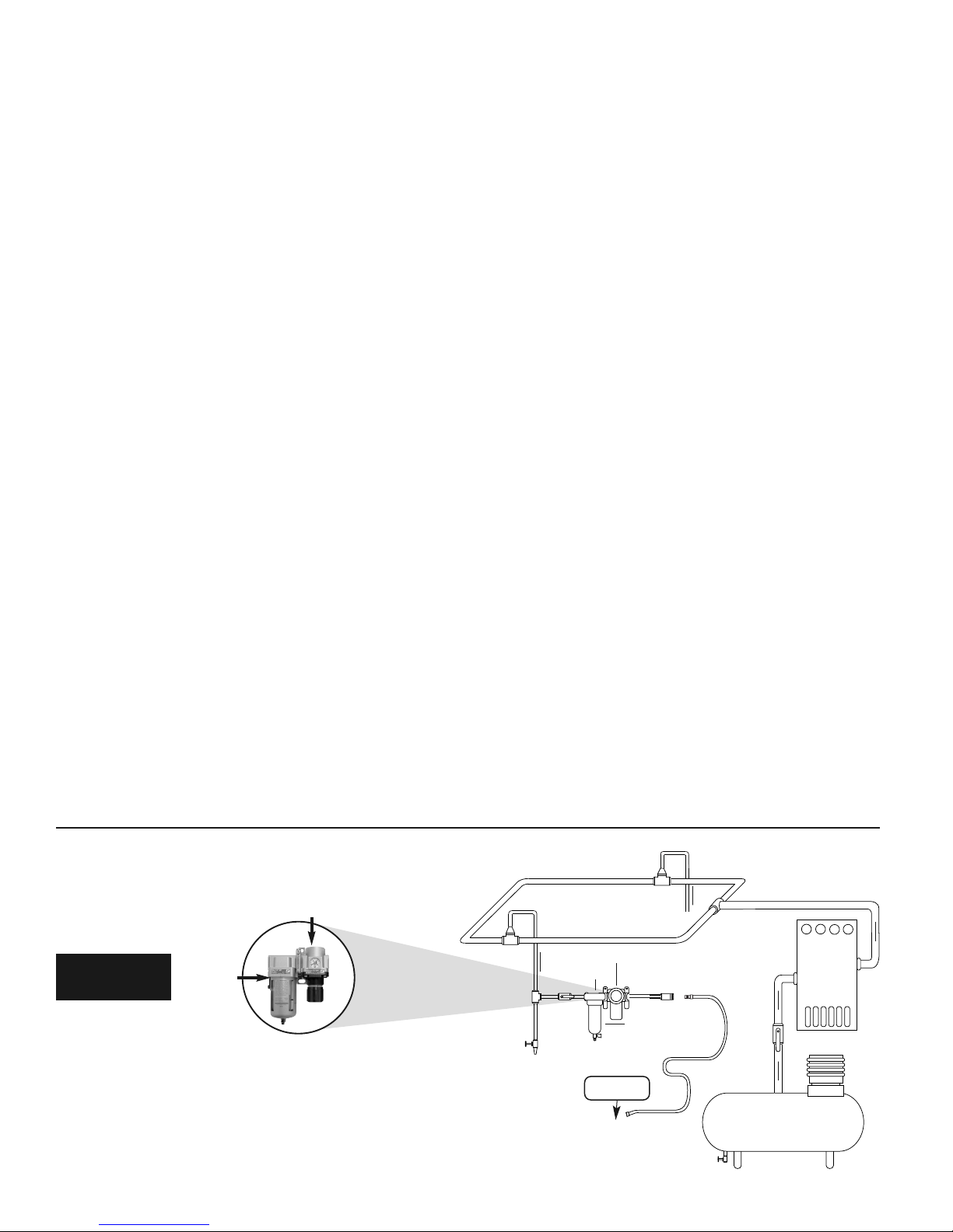
Filter
Regulator
90 PSIG
(6.2 Bar)
To Tool Station
Ball
Valve
Ball
Valve
Filter
Regulator
Air Flow
Drain
Valve
Drain
Valve
Air Tool
Air Compressor
and Receiver
Drain Valve
Air Hose
90 PSIG MAX
(6.2 Bar)
Air Flow
Refrigerated
Air Dryer
• Dynabrade Air Power Tools are designed to operate at 90 PSIG (6.2
Bar) maximum air pressure at the tool inlet, when the tool is running.
Use recommended regulator to control air pressure.
• Ideally the air supply should be free from moisture. To facilitate removing
moisture from air supply, the installation of a refrigerated air dryer after
the compressor and the use of drain valves at each tool station is
recommended.
➤
➤
➤
➤
2
AIR SYSTEM
Closed loop pipe system, Sloped in direction of air flow
OPERATING & MAINTENANCE INSTRUCTIONS
Important: To keep tool safe, a Preventative Maintenance Program is recommended. The program should included inspection of the tool and all related
accessories and consumables, including air lines, pressure regulators, filters, oilers, etc. refer to ANSI B186.1 for additional maintenance information. If
accessory or tool breakage occurs, investigate failure to determine the cause and correct before issuing tool for work. Use the following schedule as a
starting point in developing a Preventative Maintenance Program. If tool does not operate properly (RPM, Vibration, Start/Stop) after these scheduled
checks or at any time, the tool must be repaired and corrected before returning tool to use.
INSTALLATION:
• To ensure long life and dependable service, use a Closed Loop Air System and Filter-Regulator as diagramed below.
• Each tool should have its own dedicated hose connected to an air supply manifold. Quick disconnects should be installed at the manifold in an effort to
reduce contamination into the tool.
• It is strongly recommended that all Dynabrade air tools be used with a Filter-Regulator to minimize the possibility of misuse due to unclean air, wet air.
Dynabrade recommends the following: 10677 Air Line Filter-Regulator — Provides accurate air pressure regulation, two-stage filtration of
water contaminants.
• This tool should use filtered and regulated air, but does not require lubricated air. Lubricated air is not detrimental to tool life.
MAINTENANCE:
Daily (every 8 Hours):
• Inspect tool and accessories for damage or broken parts. Replace items as necessary to ensure proper operation and safety.
• Check air line pressure with a gage. (MAX. 90 PSIG or 6.2 Bar operating pressure at the air inlet of the tool.)
• Check tool for proper operation: If operating improperly or demonstrates unusual vibration, the tool must be serviced and problem corrected before
further use.
Every 20 hours or once a week which ever comes first:
• Check free speed of tool without the abrasive accessory mounted. Measure RPM (speed) with tachometer and with an air pressure gage connected at
the air inlet of the tool. Maximum air pressure while the tool is running should read 90 PSIG (6.2 Bar). If a governed tool is operating at a higher speed
than the RPM marked on the tool housing, the tool must be serviced and corrected before use. A non-governed tool may exceed the RPM marked on
the tool by 10% when operated at free speed with no accessories.
REPAIR:
• Use only genuine Dynabrade replacement parts to ensure quality. To order replacement parts, specify Model#, Serial# and RPM of your air tool.
• Mineral spirits are recommended when cleaning the tool and parts. Do not clean tool or parts with any solvents or oils containing acids, esters, ketones,
chlorinated hydrocarbons or nitro carbons.
• DO NOT clean or maintain tools with chemicals that have a low flash point (example: WD-40
®
).
• Air tool markings must be kept legible at all times, if not, reorder housing and replace. User is responsible for maintaining specification information.
• After maintenance is performed on tool verify RPM (per 20 hr maintenance schedule), vibration and operation.
HANDLING & STORAGE:
• Use of tool rests, hangers and/or balancers is recommended.
• Protect tool inlet from debris (see Notice).
• DO NOT carry tool by air hose or near the tool throttle lever.
• Store accessories in protective racks or compartments to
prevent damage.
END OF USE/DISPOSAL:
When tool has reached its end of useful service, disassemble tool into its primary components (i.e. steel, aluminum and plastic part) and recycle or
discard per local, state and/or federal regulations as to not harm the environment.
NOTICE:
All Dynabrade motors use the highest quality parts and metals available and are machined to exacting tolerances. The failure of quality pneumatic motors
can most often be traced to an unclean air supply or the lack of lubrication. Air pressure easily forces dirt or water contained in the air supply into motor
bearings causing early failure. It often scores the cylinder walls and the rotor blades resulting in limited efficiency and power. Our warranty obligation is
contingent upon proper use of our tools and cannot apply to equipment which has been subjected to misuse such as unclean air, wet air or a lack of
lubrication during the use of this tool.
• Follow the handling instructions outlined in the operating instructions
when carrying the tool and when changing accessories.
• Protect accessories from exposure to water, solvents, high humidity,
freezing temperature and extreme temperature changes.
DO NOT
Lubricate
➤
Page 3

Pencil Grinder
Complete Assembly
1 51657 Collet Cap
2 51659 1/8
"Insert
51674 3/32
" Insert
51780 1/16
" Insert
51673 3mm Insert
3 51658 Collet Guard
51725 Ext. Collet Guard
4 51548 Bearing Retainer
5 94984 Debris Eliminator
6 51544 Bearing
51685 Ceramic Bearing
7 51660 Grip (Non-Vac. Models)
8 51739 Vac. Shroud
51785 Ext. Vac. Shroud
9 51791 Vac. Hose
10 96585 Rubber Band (3)
(Vac. Models Only)
11 51790 Vac. Hose Adapter
12 Housing - See Chart
13 51661 Wave Spring
14 51651 Bearing
51686 Ceramic Bearing
15 51654 Drive Shaft
51724 Ext. Drive Shaft
16 51656 Turbine Base
17 51691 35K Governor
51692 50K Governor
51675 60K Governor
18 51678 Turbine
19 51655 Top Plate
20 51684 Muffler
21 51662 Air Bushing
22 51275 Cover-35,000 (Red)
51274 Cover-50,000 (Gold)
51273 Cover-60,000 (Teal)
23 51276 24" Air Hose*
24 51669 Retaining Ring
25 51272 Valve Body
26 95730 O-Ring (2)
27 51665 Valve
28 51664 Valve Seat
29 51663 Tip Valve
30
51676 Conical Spring
31 51271 Inlet Barb
32 51277 42" Air Hose*
33 51269 Fitting
34 56022 Inlet Screen
INDEX KEY
No. Part # Description
3
Oil: O1= Air Lube
O
A
T
KEY
23
33
32
24
25
28
26
27
29
31
30
21
12
1
2
11 10
8
15
15
16
17
18
19
20
13
14
51694 Shaft Lock Pin
95731 8mm Wrench.
4.5 N•m
T
2 N•m
T
4.5 N•m
T
Insert Part #
1/8" 51659
3/32" 51674
1/16" 51780
3mm 51673
A
8
A
7
14.1 N•m
T
A
8
A
7
Model # Housing #
51622 51635
51623 51636
51624 51637
51629 51638
51630 51639
51631 51640
51632 51641
51633 51642
51634 51645
51700 51695
51701 51696
51702 51697
51703 51698
51704 51699
51705 51646
51706 51647
51707 51648
51708 51649
51730 51737
51731 51738
51732 51795
51733 51796
51750 51741
51753 51744
51756 51747
3
22
34
4
6
5
Assy. # RPM
51766 35,000
51767 50,000
51768 60,000
*Hose Assemblies
14.1 N•m
T
A
8
Parts
Included
in Hose
Assemblies
9
A
17
The rated RPM of a mounted point is lowered if the overhang
(end of collet to abrasive) exceeds .5 inches (12.7 mm). Refer
to ANSI B 7.1 tables for overhang and additional information.
ANSI reference tables available at www.dynabrade.com
Find at Parts Page/Technical Document Page for each model.
7
Adhesive: A
7
= Loctite #222
A8= Loctite #567
A17= Loctite #454
Torque: N•m x 8.85 = In. - lbs.
Always follow adhesive manufacturers
cleaning and priming recommendations.
Page 4

Model Number RPM hp (Watt) Sound dB(A) Air Consumption Collet Size Weight Length Height
51622
35,000
.1 (75) 74
8 SCFM (227 LPM)
1/8" 1.1 (.5) 5-1/4 (132) 1-7/8 (49)
51623
35,000
.1 (75) 76
8 SCFM (227 LPM)
1/8" 1.2 (.5) 6 (152) 1-7/8 (49)
51624
35,000
.1 (75) 74
8 SCFM (227 LPM)
3 mm 1.1 (.5) 5-1/4 (132) 1-7/8 (49)
51629
50,000
.1 (75) 76
8 SCFM (227 LPM)
1/8" 1.1 (.5) 5-1/4 (132) 1-7/8 (49)
51630
50,000
.1 (75) 73
8 SCFM (227 LPM)
1/8" 1.2 (.5) 6 (152) 1-7/8 (49)
51631
50,000
.1 (75) 76
8 SCFM (227 LPM)
3 mm 1.1 (.5) 5-1/4 (132) 1-7/8 (49)
51632
60,000
.1 (75) 72
8 SCFM (227 LPM)
1/8" 1.1 (.5) 5-1/4 (132) 1-7/8 (49)
51633
60,000
.1 (75) 72
8 SCFM (227 LPM)
1/8" 1.2 (.5) 6 (152) 1-7/8 (49)
51634
60,000
.1 (75) 72
8 SCFM (227 LPM)
3 mm 1.1 (.5) 5-1/4 (132) 1-7/8 (49)
51700
60,000
.1 (75) 69
8 SCFM (227 LPM)
1/8" .8 (.4) 5-1/4 (132) 1-1/2 (37)
51701
60,000
.1 (75) 69
8 SCFM (227 LPM)
3 mm .8 (.4) 5-1/4 (132) 1-1/2 (37)
51702
60,000
.1 (75) 69
8 SCFM (227 LPM)
3/32" .8 (.4) 5-1/4 (132) 1-1/2 (37)
51703
50,000
.1 (75) 64
8 SCFM (227 LPM)
1/8" .8 (.4) 5-1/4 (132) 1-1/2 (37)
51704
50,000
.1 (75) 64
8 SCFM (227 LPM)
3 mm .8 (.4) 5-1/4 (132) 1-1/2 (37)
51705
50,000
.1 (75) 64
8 SCFM (227 LPM)
3/32" .8 (.4) 5-1/4 (132) 1-1/2 (37)
51706
35,000
.1 (75) 65
8 SCFM (227 LPM)
1/8" .8 (.4) 5-1/4 (132) 1-1/2 (37)
51707
35,000
.1 (75) 65
8 SCFM (227 LPM)
3 mm .8 (.4) 5-1/4 (132) 1-1/2 (37)
51708
35,000
.1 (75) 65
8 SCFM (227 LPM)
3/32" .8 (.4) 5-1/4 (132) 1-1/2 (37)
51730
50,000
.1 (75) 69
8 SCFM (227 LPM)
1/8" .8 (.4) 5-1/4 (132) 1-1/2 (37)
51731
60,000
.1 (75) 69
8 SCFM (227 LPM)
1/8" .8 (.4) 5-1/4 (132) 1-1/2 (37)
51732
50,000
.1 (75) 64
8 SCFM (227 LPM)
3 mm .8 (.4) 5-1/4 (132) 1-1/2 (37)
51733
60,000
.1 (75) 69
8 SCFM (227 LPM)
3 mm .8 (.4) 5-1/4 (132) 1-1/2 (37)
51750
60,000
.1 (75) 69
8 SCFM (227 LPM)
1/8" .8 (.4) 6 (152) 1-1/2 (37)
51753
50,000
.1 (75) 69
8 SCFM (227 LPM)
1/8" .8 (.4) 6 (152) 1-1/2 (37)
51756
35,000
.1 (75) 69
8 SCFM (227 LPM)
1/8" .8 (.4) 6 (152) 1-1/2 (37)
DYNABRADE, INC. www.dynabrade.com
8989 Sheridan Drive • Clarence, NY 14031-1490 • Phone: (716) 631-0100 • Fax: 716-631-2073 • International Fax: 716-631-2524
© DYNABRADE, INC., 2010 PD10.37_rev.2_03/14
1. American National Standards
Institute – ANSI
25 West 43rdStreet
Fourth Floor
New York, NY 10036
Tel: 1 (212) 642-4900
3. Power Tool Institute, Inc.
P.O. Box 818
Yachata, Oregon 97498-0818
Tel: 1 (503) 547-3185
4. European Committee for
Standardization
Rue de Stassart 36
B - 1050 Brussels, Belgium
2. Government Printing Office – GPO
Superintendent of Documents
Attn. New Orders
P.O. Box 371954
Pittsburgh, PA 15250-7954
Tel: 1 (202) 512-1803
OPTIONAL ACCESSORIES SPECIAL REPAIR TOOLS
MACHINE SPECIFICATIONS
REFERENCE CONTACT INFORMATION
LIFETIME WARRANTY
To validate Dynabrade Lifetime Warranty, you must register each tool at: www.dynabrade.com. Registration of each tool at website is required. Dynabrade
will not honor Lifetime Warranty on unregistered tools. Please view the entire Lifetime Warranty Policy at : www.dynabrade.com.
94999 – Air Bushing Tool
96406 – .18" Dia. Pilot Punch
96407 – Bearing Retainer Wrench
96408 – Top Plate Wrench
96418 – Bearing Press Tool
.623" O.D., .375" I.D.
96419 – Bearing Press Tool
.498" O.D., .315" I.D.
96479 – Extension Retainer Wrench
96483 – Sleeve Assembly Bullet
96486 – Collet Insert Removal Tool
96439 – Extension Collet Guard Wrench
Additional Specifications: Air Inlet Thread 1/4" NPT • Hose Size 1/4" (6 mm)
Sound Level is the pressure measurement outlined in ISO regulation ISO-15744
P/N 93351
• 1/8" Carbide Burr Kit, includes 12 burrs for
grinding, deburring, and finishing.
P/N 51685 Ceramic Bearing (Front)
P/N 51686 Ceramic Bearing (Rear)
• Provide better performance and durability in
the face of the following environmental factors:
high speeds, dirt, corrosion and extreme
temperatures.
Model 10677: Up to 55 SCFM @ 145 PSIG
1/2" NPT Female ports, includes (2)
3/8" NPT reducers.
• Filter-Regulator, provides accurate air pressure
regulation and two stage filtration of
water/contaminates.
 Loading...