

Page 1
GENERAL SAFETY RULES
WARNING! Read and understand all instructions. Failure to follow all instructions listed below, may result in electric shock, fire and /or serious personal injury.
SAVE THESE INSTRUCTIONS
Work Area
1. Keep your work area clean and well lit. Cluttered benches and dark areas invite accidents.
2. Do not operate power tools in explosive atmospheres, such as in the presence of flammable liquids, gases, or dust. Power tools create sparks which ignite
the dust or fumes.
3. Keep bystanders, children, and visitors away while operating a power tool. Distractions can cause you to lose control.
Electrical Safety
1. Double Insulated tools are equipped with a polarized plug (one blade is wider than the other.) This plug will fit in polarized outlet only one way. If the plug
does not fit fully in the outlet, reverse the plug. If it still does not fit, contact a qualified electrician to install a polarized outlet. Do not change the plug in
any way. Double Insulation eliminates the need for the three wire grounded power cord and grounded power supply system.
2. Avoid body contact with grounded surfaces such as pipes, radiators, ranges and refrigerators. There is an increased risk of electric shock if your body is grounded.
3. Don't expose power tools to rain or wet conditions. Water entering a power tool will increase the risk of electric shock.
4. Do not abuse the cord. Never use the cord to carry the tools or pull the plug from an outlet. Keep cord away from heat, oil, sharp edges or moving parts.
Replace damaged cords immediately. Damaged cords increase the risk of electric shock.
(continued on next page)
Parts Page Reorder No. PD05•28
Effective July, 2005
Supersedes PD05•08
Tool Manual – Safety, Operation and Maintenance
SAFETY LEGEND
G
Read and understand tool manual before
work starts to reduce risk of injury to
operator, visitors, and tool.
Eye protection must be worn at all times,
eye protection to conform to ANSI Z87.1.
Respiratory protection to be used when exposed to
contaminants that exceed the applicable threshold
limit values required by law.
Practice safety requirements. Work alert,
have proper attire, and do not operate tools under
the influence of alcohol or drugs.
Ear protection to be worn when exposure to sound,
exceeds the limits of applicable Federal, State or
local statues, ordinances and/or regulations.
Electric shock hazard. Avoid bodily contact with
grounded objects, bodies of water.
Do not damage cord set.
Read and understand this tool manual before operating your tool. Follow all safety rules for the protection of operating personnel as well
as adjacent areas. For safety information, refer to Code of Federal Regulation – CFR 29 Part 1910, European Committee for Standards (EN)
Hand Held Electric Motor Operated Tools – Safety Requirements and applicable State and Local Regulations.
SAVE THIS DOCUMENT, EDUCATE ALL PERSONNEL
Some dust created by grinding, drilling, and other construction activities contain chemicals known to cause cancer, birth defects or
other reproductive harm. Some examples of these chemicals are:
• Lead from lead-based paints
• Crystalline silica from bricks and cement and other masonry products
• Arsenic and chromium from chemically treated lumber
Your risk from these exposures varies, depending on how often you do this type of work. To reduce your exposure to these chemicals: work in a well
ventilated area, and work with approved safety equipment, such as those dust masks that are specially designed to filter out microscopic particles.
Caution: Hand, wrist and arm injury may result from repetitive work, motion and overexposure to vibration.
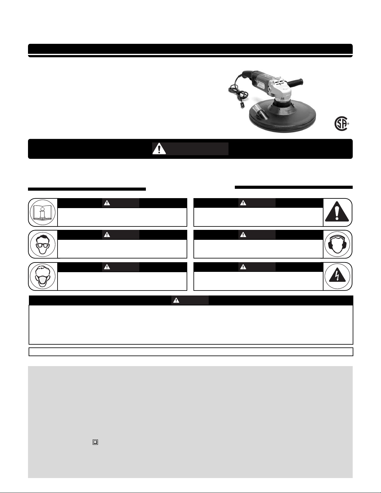
Tool Intent: Dynabrade Random Orbital Sander for sanding, leveling solid surfaces, fillers, etc.
11" Random Orbital Sanders
Electronic Variable Speed
Models:
51612 - Non-Vac
- 0-3,000 RPM Dial
- Variable Speed On/Off Switch
- 120V
51613 - Central-Vac (1-1/4" Port)
- 0-3,000 RPM Dial
- Variable Speed On/Off Switch
- 120V
CUS
WARNIN
WARNING
WARNING
WARNING
WARNING
WARNING
WARNING
WARNING
Page 2

2
Electrical Safety (Continued)
5. When operating a power tool outside, use an outdoor extension cord marked “W-A” or “W.” These cords are rated for outdoor use and reduce the
risk of electric shock.
Personal Safety
1. Stay alert, watch what you are doing and use common sense when operating a power tool. Do not use tool while tired or under the influence of drugs,
alcohol, or medication. A moment of inattention while operating power tools may result in serious personal injury.
2. Dress properly. Do not wear loose clothing or jewelry. Contain long hair. Keep your hair, clothing, and gloves away from moving parts. Loose clothes,
jewelry, or long hair can be caught in moving parts.
3. Avoid accidental starting. Be sure switch is off before plugging in. Carrying tools with your finger on the switch or plugging in tools that have the switch
on invites accidents.
4. Remove adjusting keys or switches before turning the tool on. A wrench or a key that is left attached to a rotating part of the tool may result in personal injury.
5. Do not overreach. Keep proper footing and balance at all times. Proper footing and balance enables better control of the tool in unexpected situations.
6. Use safety equipment. Always wear eye protection. Dust mask, non-skid safety shoes, hard hat, or hearing protection must be used for appropriate conditions.
Tool Use and Care
1. Use clamps or other practical way to secure and support the workpiece to a stable platform. Holding the work by hand or against your body is unstable and may
lead to loss of control.
2. Do not force tool. Use the correct tool for your application. The correct tool will do the job better and safer at the rate for which it is designed.
3. Do not use tool if switch does not turn it on or off. Any tool that cannot be controlled with the switch is dangerous and must be repaired.
4. Disconnect the plug from the power source before making any adjustments, changing accessories, or storing the tool. Such preventative safety measures
reduce the risk of starting the tool accidentally.
5. Store idle tools in a high, dry place, locked up out of reach of children and other untrained persons. Tools are dangerous in the hands of untrained users.
6. Maintain tools with care. Keep cutting tools sharp and clean. Properly maintained tools, with sharp cutting edges are less likely to bind and are easier to control.
7. Check for misalignment or binding of moving parts, breakage of parts, and any other condition that may affect the tools operation. If damaged, have the
tool serviced before using. Many accidents are caused by poorly maintained tools.
8. Use only accessories that are recommended by the manufacturer for your model. Accessories that may be suitable for one tool, may become hazardous
when used on another tool.
9. Use the right tool. Do not force small tools or attachments to do the job of a heavy duty tool.
Service
1. Tool service must be performed only by qualified repair personnel. Service or maintenance performed by unqualified personnel could result in a risk of injury.
2. When servicing a tool, use only identical replacement parts. Follow instructions in the Maintenance section of this manual. Use of unauthorized parts or failure
to follow Maintenance Instructions may create a risk of electric shock or injury.
SPECIFIC SAFETY RULES
1. Accessories must be rated for at least the speed recommended on the tool warning label. Wheels and other accessories running over rated speed can fly
apart and cause injury.
2. Hold tool by insulated gripping surfaces when performing an operation where the tool may contact hidden wiring or its own cord. Contact with a “live”
wire will make exposed metal parts of the tool “live” and shock the operator.
(See Definitions for label symbols on pg. 3)
TOOL DESCRIPTION
Random Orbital Sander – Is a random orbital electric hand tool which includes: a variable speed on/off switch; side handle; a RPM Dial which maintains desired RPM, when
under load; and is equipped with an 8 ft. cord set.
ASSEMBLY and OPERATION INSTRUCTIONS
1. With power source disconnected from tool, securely fasten abrasive/accessory on tool by depressing spindle locking button located on the right angle head. The rated
RPM of the accessory must be equal to or greater than the rated RPM of the tool.
2. Hold tool by the motor housing and the side handle. Do Not hold tool by head/housing assembly. Keep hands away from all sanding edges and moving parts.
3. Tool has variable RPM dial on top side of rear handle. Dial desired maximum RPM (see label B) and then proceed to follow step 4.
4. Squeeze variable speed on/off switch on rear handle to run tool. Tool's on/off switch maybe used as a throttle to fluctuate RPM. To lock tool in “on” position continue
to squeeze on/off switch and depress side button. Electronic module maintains specified speed even under load. To disengage tool when locked in “on” position push
on/off switch inward.
MAINTENANCE and ACCESSORY CARE INSTRUCTIONS
Important: A preventative maintenance program is recommended whenever portable power tools are used.
•
Use only genuine Dynabrade replacement parts to insure quality. To order replacement parts, specify Model #, Serial # and RPM of your tool.
Routine Preventative Maintenance:
•
Mineral spirits are recommended when cleaning the sanding heads. Do not use on electrical components or clean tool or parts with any solvents or oils containing acids,
esters, ketones, chlorinated hydrocarbons or nitro carbons. Blow the dirt from electrical components with air.
•
DO NOT clean or maintain tools with chemicals that have a low flash point (example: WD-40
®
).
•
Tool labels must be kept legible at all times, if not, reorder label(s) and replace. User is responsible for maintaining specification information i.e.:
Model #, S/N, and RPM. (See Assembly Breakdown)
•
Visually inspect plugs and cords for frays, visible damage and signs of deterioration. Replace damaged or worn components.
•
Refer to Dynabrade's Warning/Safety Operating Instructions Tag (Reorder No. 95903) for safety information.
•
Brush Changing – Unplug tool and remove brush caps and replace brushes. Replace brush caps. Brush changing – Change brushes every 225 hrs. to ensure proper tool
function. After changing brushes, caps etc. it is recommended to replace the right angle gear grease with 95542 Grease.
•
After maintenance is performed on tool check for excessive tool vibration.
•
Check for excessive current leakage at 550 volts with a current leakage checker on all screws and the gear case, if the electrical components have been
disturbed during repair.
Handling and Storage of Tool and Accessories:
•
Use of tool rests, hangers and/or balancers is recommended.
•
DO NOT carry tool by cord.
•
Protect abrasive accessories from exposure to water, solvents, high humidity, freezing temperature and extreme temperature changes.
•
Store accessories in protective racks or compartments to prevent damage.
Page 3

Vacuum Shroud Assembly
Complete 11" Random Orbital Sander Assembly
3
1 89254 Shaft
2 89252 Key
3 89259 C-Ring (2)
4 89261 Screw (4)
5 89251 Dust Cap
6 89253 Gear Box
7 89255 Bearing
8 89256 Bearing Plate
9 89257 Screw (3)
10 89258 Gear
11 89260 Washer
12 89264 Screw (2)
13 89262 Screw (4)
14 89263 Shaft Lock Pin
15 89267 Spring
16 89268 Button
17 89265 Needle Bearing
18 89266 Gear Box
19 89270 Bearing
20 89271 Bearing Plate
21 89276 Brush Holder (2)
22 89275 Terminal (2)
23 89274 Brush (2)
24 89273 Brush Cap (2)
25 89272 Brush Set Assembly (2)
26 89277 Speed Control
27 89279 Screw
28 89278 Switch
29 89282 Strain Relief
30 89283 Screw (2)
31 89281 Cord Guard
32 89280 Power Cord
33 89292 Armature Assembly
34 97592 Washer
35 02649 Bearing
36 89293 Bearing Holder
37 97589 Screw (5)
38 51728 Rear Housing, Left
39 51719 Rear Housing, Right
40 89294 Plate
41 97596 Screw
42 89295 Field
43 51718 Housing
44 89297 Field/Housing Assembly
45 89296 Magnet
46 97599 E-Ring
47 61366 Mounting Collar
48 01791 Washer
49 01790 Screw
50 61368 Vac. Shroud Assembly
51 95886 Washer (11)
52 96425 Screw (6)
53 61362 1-1/4" Vac Adapter
54 61361 Lip Seal
55 61356 Guard Assembly
56 97547 Spacer
57 95344 Screw (3)
58 61351 Adapter
59 61354 Spacer (2)
60 61352 Counterweight
61 96557 Screw (2)
62 94914 Spacer
63 54520 Bearing (2)
64 96118 Screw (3)
65 61353 Mount Plate
66 61355 Bearing Shaft
67 56231 Hook-Face Backing Pad
68 95178 Screw (5)
69 18553 Side Handle
Index Key
No. Part # Description
Brush Set
Assembly
Field/Housing
Assembly
B
D
25
21
22
23
24
A
C
32
26
29
28
27
16
15
12
13
17
14
18
4
11
10
9
7
6
5
2
1
3
4
8
19
20
39
38
37
33
34
35
40
42
43
45 46
41
36
30
31
A 89289 Rating Label - 51612
89290 Rating Label - 51613
B 89284 RPM Label
C 89286 Warning Label
D 89287 Logo
Label Key
Item Part # Description
A . . . . . . . . . . . . . . . . . . . . .amperes
Hz . . . . . . . . . . . . . . . . . . . . . . . .hertz
. . . . . . . . . .Class II Construction
Definitions of Label Symbols
Symbol Description
To order replacement parts, specify model number and serial number of your machine.
Country of Origin of Electric Motor: Made in Taiwan
44
69
47
T
A
Adhesive:
A3= Loctite #242
A8= Loctite #567
Torque: N•m x 8.85 = In. - lbs.
KEY
A
8
A
3
A
3
20 N•m
T
3 N•m
T
5.7 N•m
T
LEFT HAND
THREADS
48 49
52
54
53
52
51
51
50
57
59
60
61
58
56
62
64
63
65
67
51
68
66
55
95134 Hex Key Wrench (9/64 in.)
Page 4

One Year Warranty
Following the reasonable assumption that any inherent defect which might prevail in a product will become apparent to the user within one year from the date of
purchase, all equipment of our manufacture is warranted against defects in workmanship and materials under normal use and service. We shall repair or replace
at our factory, any equipment or part thereof which shall, within one year after delivery to the original purchaser, indicate upon our examination to have been
defective. Our obligation is contingent upon proper use of Dynabrade tools in accordance with factory recommendations, instructions and safety practices. It shall
not apply to equipment which has been subject to misuse, negligence, accident or tampering in any way so as to affect its normal performance. Normally
wearable parts such as bearings, brushes, gears, etc., are not covered under this warranty.
Machine Specifications
DYNABRADE, INC.,
8989 Sheridan Drive •Clarence, NY 14031-1490 •Phone: (716) 631-0100 •Fax: 716-631-2073 •International Fax: 716-631-2524
© DYNABRADE, INC., 2005 PRINTED IN USA PD05.28_07/05
Visit Our Web Site: www.dynabrade.com Email: Customer.Service@Dynabrade.com
1. American National Safety Institute – ANSI
25 West 43
rd
Street
Fourth Floor
New York, NY 10036
Tel: 1 (212) 642-4900
Fax: 1 (212) 398-0023
3. European Committee for Standardization
Rue de Stassart 36
B - 1050 Brussels, Belgium
2. Government Printing Office – GPO
Superintendent of Documents
Attn. New Orders
P.O. Box 371954
Pittsburgh, PA 15250-7954
Tel: 1 (202) 512-1803
Reference Contact Information
Optional Accessories
Model Motor Motor Weight Length Height
Number RPM hp (w) Voltage Current Phase Frequency Pound (kg) Inch (mm) Inch (mm)
51612 0 - 3,000 1.1 (835) 120 V (AC) 9 Amp 1 60 Hz 11.3 (5.1) 21 (533) 7-1/4 (186)
51613 0 - 3,000 1.1 (835) 120 V (AC) 9 Amp 1 60 Hz 12.5 (5.7) 21-1/2 (546) 7-1/4 (186)
95542 Grease 10 oz.
•
High film strength; excellent
resistance to water, steam, etc.
•
Workable range 0˚ F to 300˚ F.
Accessories are available for
sanding. Check our website and
literature to review all items.
FIND THE MOST CURRENT OFFERING OF ACCESSORIES AND SUPPORT DOCUMENTS @ WWW.DYNABRADE.COM
Wiring Diagram
AC 120V ~ 60Hz
6 Speed
Variable
Control
Trigger
Switch
Stator
Rotor
®
DYNABRADE
 Loading...