

Page 1
Disassembly Instructions - Wet, Stone Polisher
Model: 51520
Important: Use these instructions along with tool parts page or manual.
Notice:
Shut off air supply and depress throttle lever to deplete air.
Disconnect tool from air supply hose.
Shut off water supply faucet and disconnect.
Remove all accessories (abrasive product, backup disc, and flanges) from tool.
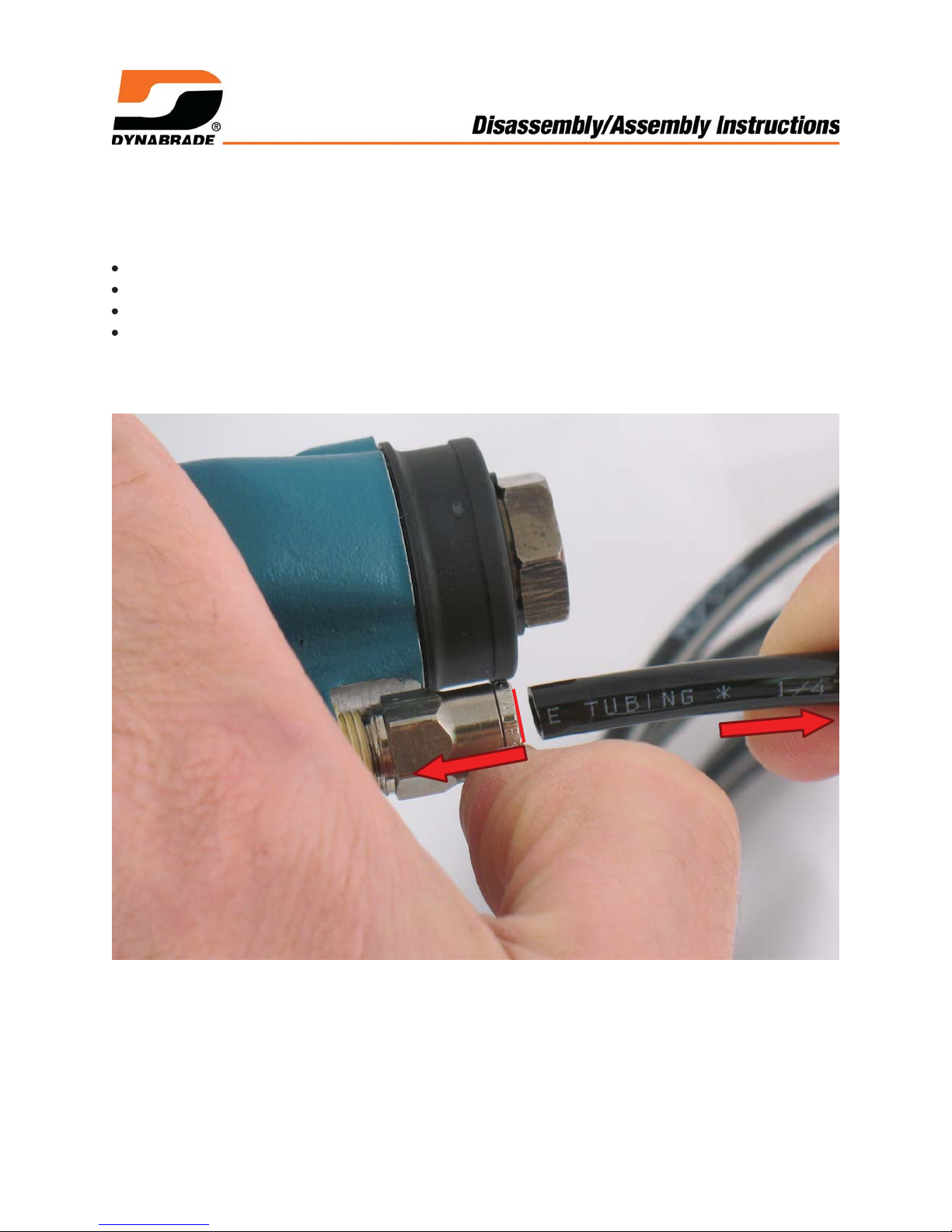
Motor Disassembly:
1. Push against collar of 96227 Fitting and pull 95579 Water Line tubing from fitting.
Page 2
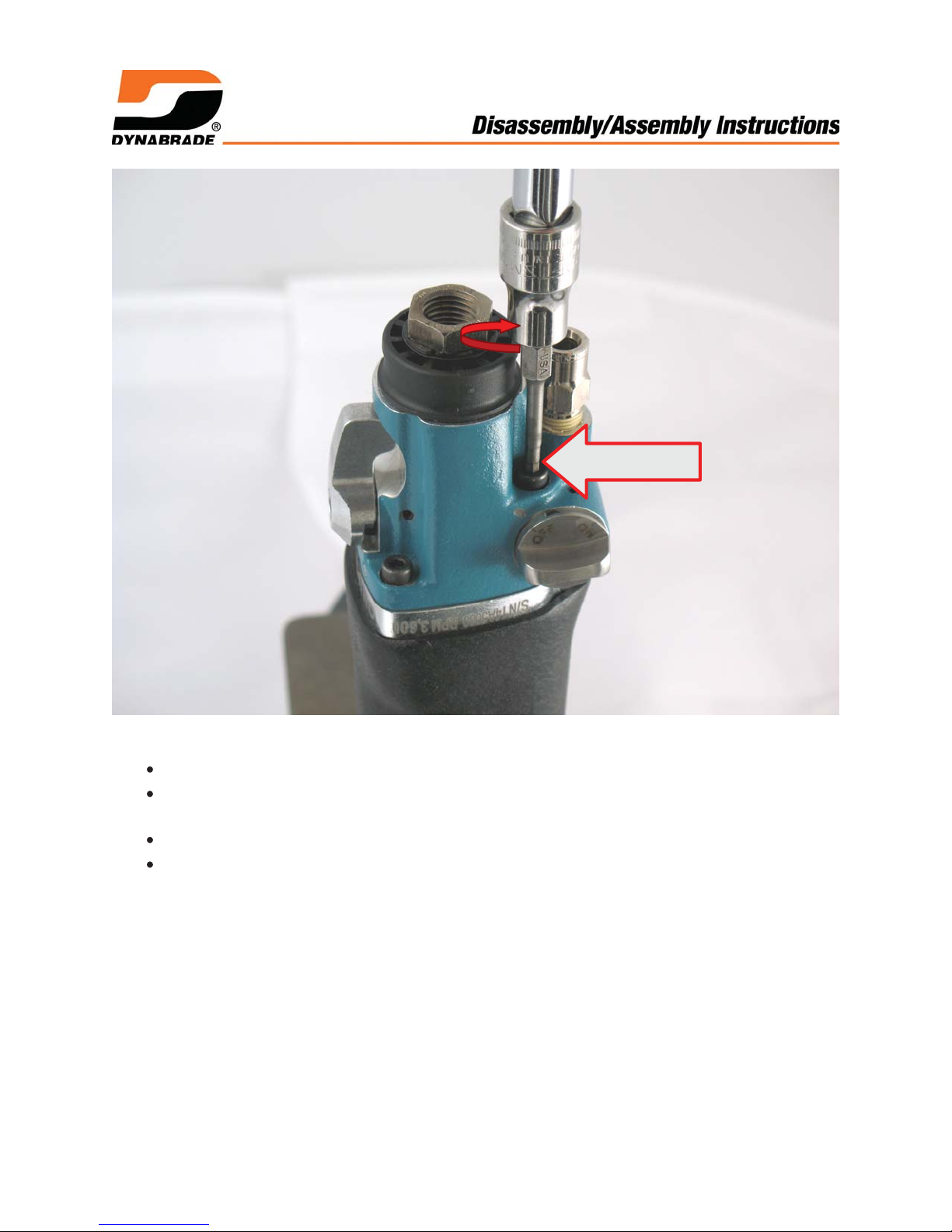
3 mm hex key
2. Install 95492 Screws (5/16"-18 SHC) in two handle bosses on housing.
Fasten 95492 Screws in vise to hold tool with 51546 Valve Body pointing up.
Use a 3 mm hex key to remove 96296, 95916 Screws along with 01211 Lock
Washers. Turn counterclockwise.
Carefully remove valve body assembly, spacers, gaskets and o-rings.
Set aside and save parts.
Page 3
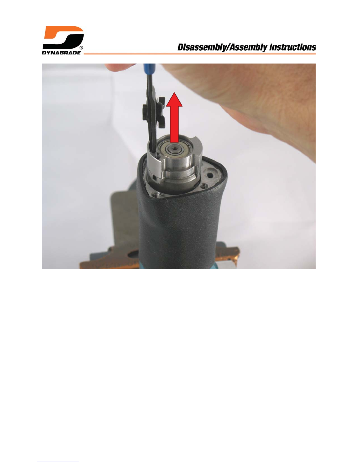
3. Remove motor form housing.
Page 4
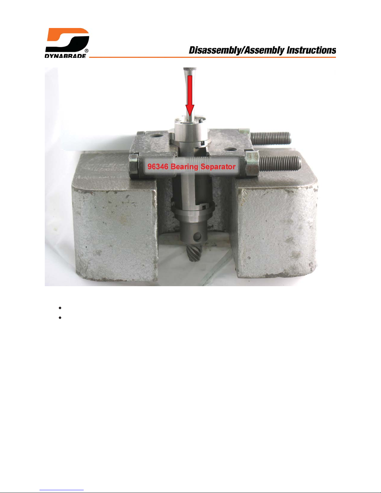
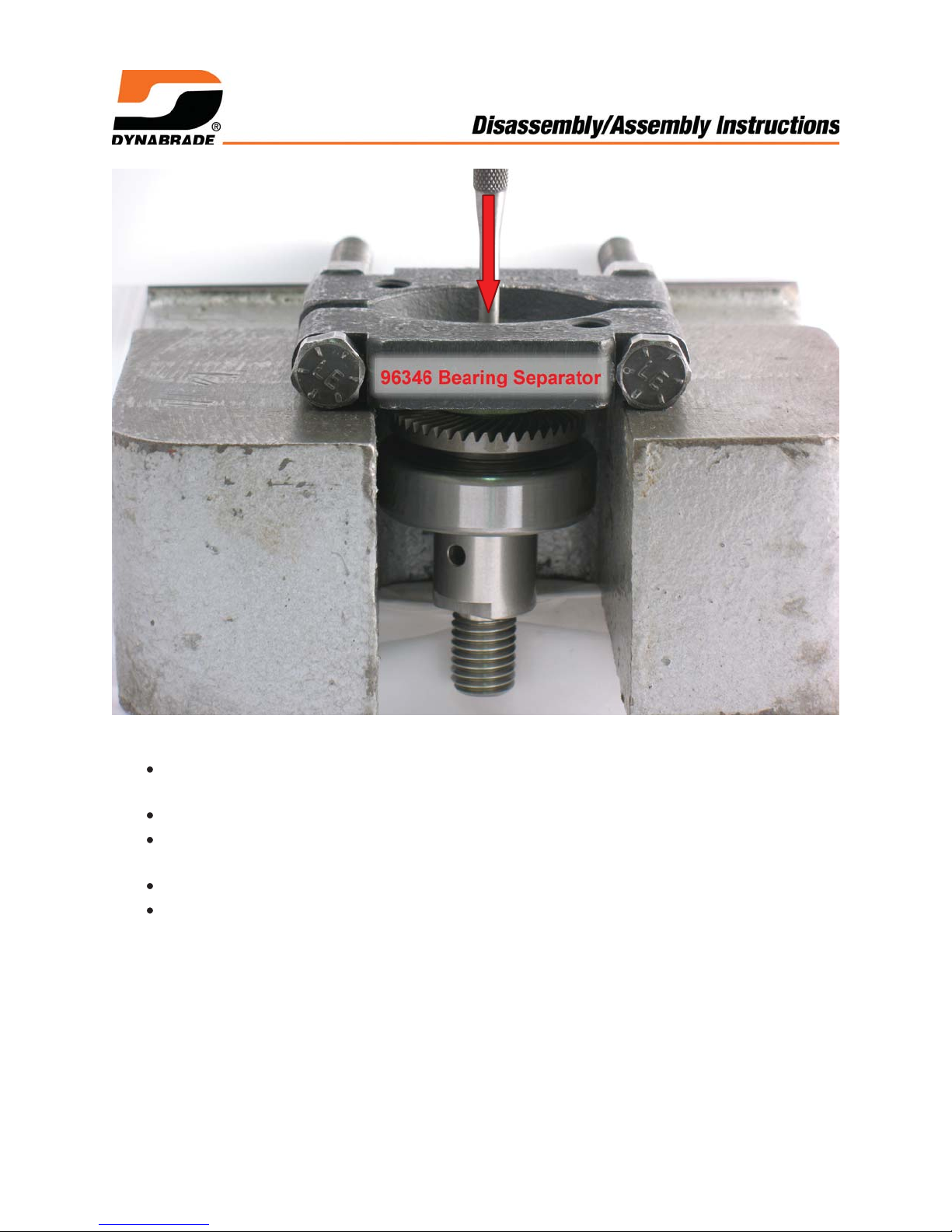
96346 Bearing Separator
4. Fasten 96346 Bearing Separator (2") around 01028 Cylinder.
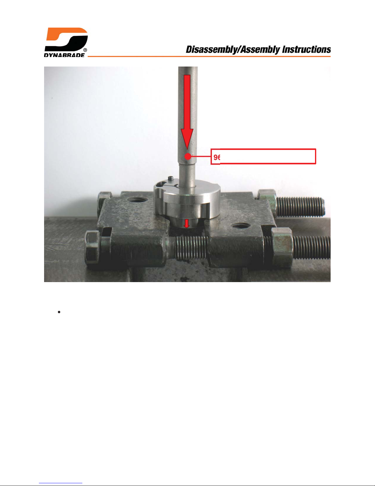
Place assembly in 96232 Arbor Press (#2) with pinion pointing down.
Use a Ø 1/4" drive punch to push 02373 Rotor out of 02649 Bearing.
Page 5
96213 Bearing Removal Tool
5. NOTICE: In the same way, use bearing separator, arbor press and 96213 Bearing
Removal Tool, to remove 02649 Bearing from 01732 Rear Bearing Plate.
Save parts.
Page 6
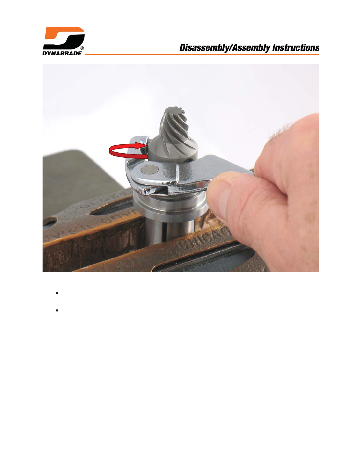
6. Fasten 02373 Rotor in vise with aluminum or bronze jaws, with pinion pointing up.
Use an adjustable hook spanner wrench to remove 51513 Pinion Gear. Turn
counterclockwise.
Remove front bearing, plate, spacer and shims.
Motor disassembly completed.
Clean and inspect parts for wear or damage. Save and reuse good parts.
Page 7
Right Angle Gear Disassembly:
HEAT
GUN
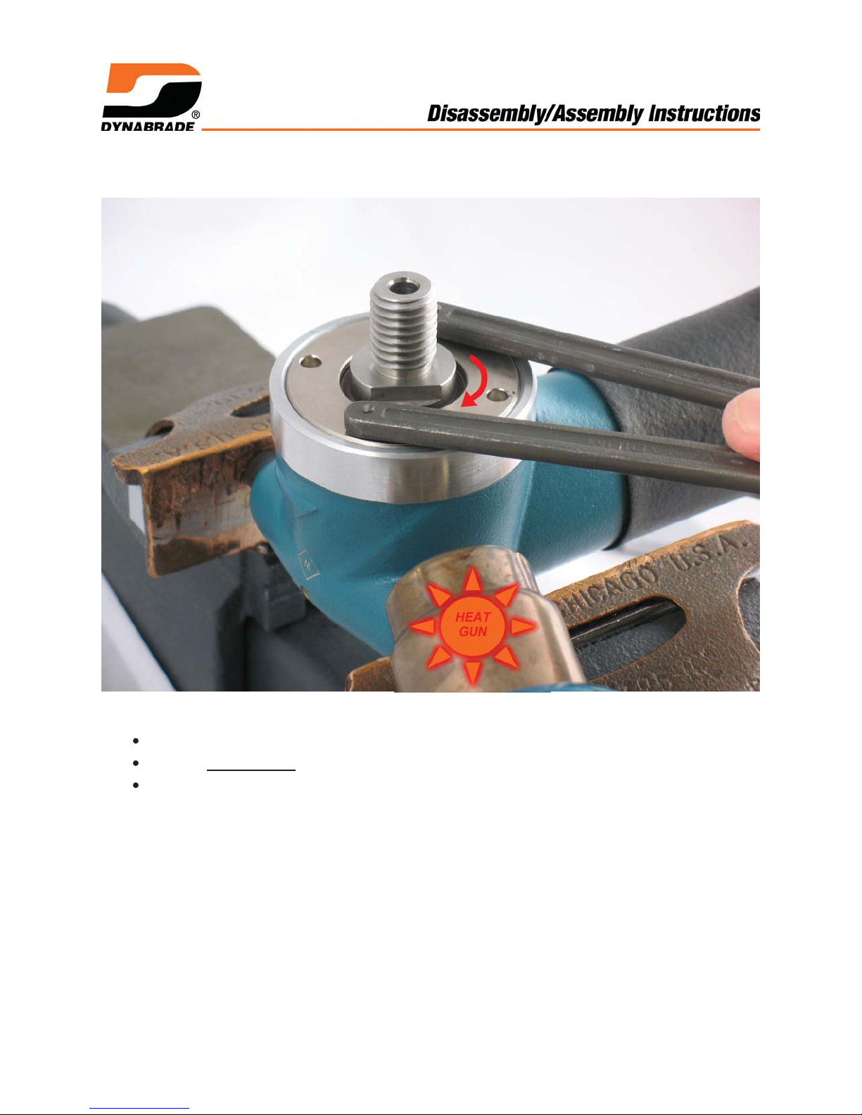
1. Install 95492 Screws (5/16"-18 SHC) in two handle bosses on housing.
Fasten 51545 Housing in vise with spindle pointing up.
Use a HEAT GUN to warm housing.
Use an adjustable pin spanner wrench to remove 51551 Spindle Retainer. Turn
clockwise. Left Hand Thread.
Page 8
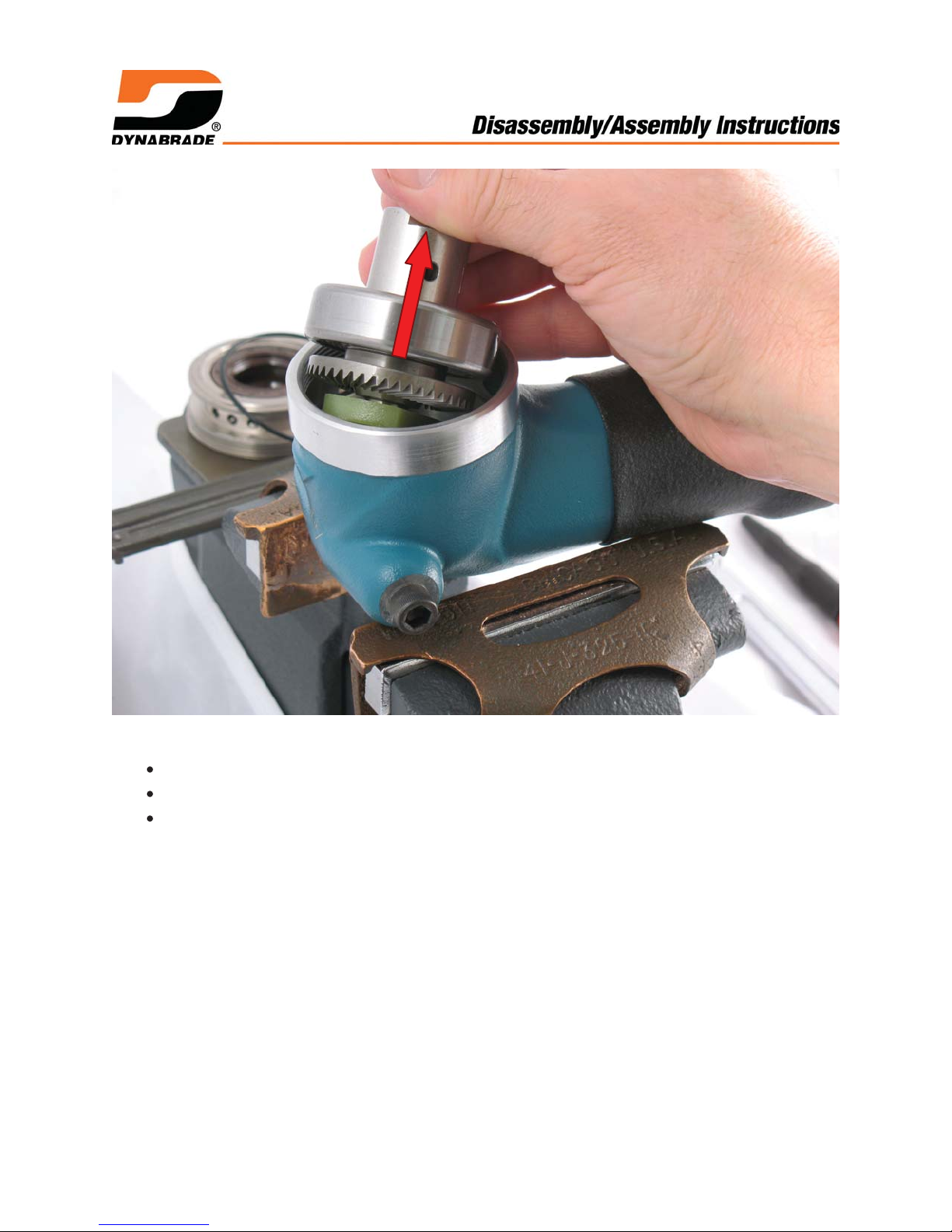
2. Loosen vise and remove housing.
Remove 96584 O-Ring.
Remove spindle and bevel gear assembly.
Remove 98243 Wave Spring.
Page 9
96346 Bearing Separator
3. Fasten 96346 Bearing Separator (2") under 02057 Bearing.
Place assembly in 96232 Arbor Press (#2) with threaded end of spindle pointing
down.
Use a Ø 3/16" drive punch to push spindle out of 02057 Bearing.
NOTICE: In the same way, use bearing separator and arbor press to remove
51514 Gear and 02685 Bearing.
IMPORTANT: Inspect 95913 Seals and 51550 Spindle. Replace worn parts!
NOTICE: Loctite #380 is used to retain 95913 Seals in 51551 Spindle Retainer.
Acetone can be used to soften adhesive and remove seals. SEE: Right Angle
Gear Assembly.
Right angle gear disassembly completed.
Clean and inspect all parts for wear or damage. Only reuse good parts.
Notice: To disassemble and assemble muffler and valve components, refer to
parts page or tool manual and follow exploded view instructions.
Page 10

Motor Assembly:
Assembly Instructions - Wet, Stone Polisher
1. Install 01010 Spacer onto rotor.
Install .003" (~0.08 mm) shim thickness into 02375 Front Bearing Plate.
Install 01007 Bearing into front bearing plate.
Install bearing and plate onto rotor.
Page 11

2. Install 51513 Pinion Gear hand tight.
Place end of pinion gear against a solid surface. Push down on front bearing
plate.
Use a .001" (~0.03 mm) thick feeler gauge to check clearance between rotor
and plate.
Notice: Clearance should be .001"-.0015" (~0.03-0.04 mm). If rotor/plate
clearance needs further adjustment, repeat steps 1 and 2. Remove or add shims
as necessary.
.001"-.0015"
(~0.03-0.04 mm)
Page 12

Torque to 17 N•m/~150 lbs. in.
3. Fasten 02373 Rotor in vise with aluminum or bronze jaws.
Use an adjustable hook spanner wrench to tighten 51513 Pinion Gear.
Torque to 17 N•m/~150 lbs. in.
Page 13

OIL
4. Apply 95842 Dynabrade Air Lube or equivalent to 01185 Vanes.
Install vanes into rotor.
Page 14

96240 Bearing Press Tool
5. Use RAISED OUTSIDE DIAMETER of 96240 Bearing Press Tool to install 02649
Bearing into 01732 Rear Bearing Plate.
Page 15

96240 Bearing Press Tool
JUST TOUCH
6. Use RAISED INSIDE DIAMETER of 96240 Bearing Press Tool and arbor press to
install 02649 Bearing and rear bearing plate onto rotor.
Carefully press bearing and plate down until plate just touches cylinder. This
will produce a close fit between bearing plates and cylinder.
Page 16

HEAT
GUN
7. Use a HEAT GUN to warm and expand housing.
Page 17

51560 Spacer
8. Use 51560 Spacer as a guide to position and install air motor.
Page 18

01024 O-Ring
51552 Gasket
9. Install 01024 O-Ring and 51552 Gasket.
Page 19

51560 Spacer •
51569 Spacer
01024 O-Ring
51113 Gasket
51568 Spacer
10. Install 51560 Spacer, 51569 Spacer & 01024 O-Ring, 51113 Gasket & 51568
Spacer.
Page 20

Torque to 4.5 N•m/~40 lbs. in.
11. Install 51546 Valve Body assembly.
Use 3 mm hex key to install 96296 & 95916 Screws with 01211 Lock Washers.
Torque to 4.5 N•m/~40 lbs. in.
Important: Check operation of air motor.
Connect tool air inlet, to an air supply that delivers a maximum of 90 PSIG (6.2
Bar) operating air pressure.
If motor operates smooth and regular continue with right angle gear assembly.
If motor does not operate or performance is erratic, disconnect tool and correct
problem before continuing.
Motor assembly completed.
Page 21

Right Angle Gear Assembly:
1. Notice: To remove 95913 Seals. Soak 51551 Spindle Retainer with old seals in a
closed container of acetone overnight. Seals will be released from retainer.
Page 22

2. Install first 95913 Seal so that open-side will face toward inside of 51545 Housing.
To install seal use Ø 1½" (~38 mm) press tool against OUTSIDE EDGE of seal.
Use 96232 Arbor Press to push seal all the way into 51551 Spindle Retainer.
Ø 1½" (~38 mm) press tool
Page 23

ACETONE
3. To install second seal, use acetone to clean inside Ø of 51551 Spindle Retainer and
outside Ø of 95913 Seal.
Apply a bead of Loctite #380 Black Max or equivalent to outside Ø of seal.
Loctite #380 Black Max
Page 24

LEVEL
Apply 95848 Gear Oil
4. Install second 95913 Seal with open-side facing in toward first seal.
Use Ø 111/16" (~43 mm) press tool, FLAT against seal.
Make seal level with surface of 51551 Spindle Retainer.
Allow 30 minutes for adhesive to cure.
Apply a small amount of 95848 Gear Oil to lip of each seal.
Page 25

Ø outside ~1.0781 (~27 mm)
5. Use deep-well socket with Ø outside ~1.0781 (~27 mm) and arbor press.
Install 02685 Bearing and 51514 Gear.
Page 26

Use 96242 Bearing Press Tool
Saturate using 95848 Gear Oil
Press bearing level
with end of spindle.
6. Saturate 53608 Wick using 95848 Gear Oil.
Install 53608 Wick.
Use RAISED INSIDE DIAMETER of 96242 Bearing Press Tool to install 02057
Bearing. Notice: Make bearing level with end of spindle.
Page 27

7. Install 98243 Wave Spring in housing.
Use one to two 96554 Shims (.003"-.006" or ~0.08 - 0.15 mm) from 96570 Shim
Pack and install into housing.
By eye, line-up notch in 53608 Wick, with lobe in housing.
Carefully install spindle assembly.
Install 96564 O-Ring.
Page 28

Torque to 23 N•m/~200 lbs. in.
8. Apply a small amount of Loctite #567 to threads on 51551 Spindle Retainer.
Carefully install spindle retainer so as not to damage seals.
Use an adjustable pin spanner wrench to fasten spindle retainer.
Turn counterclockwise. Left Hand Thread. Torque to 23 N•m/~200 lbs. in.
Page 29

360°
9. Fasten an adjustable wrench thumb tight onto flats of spindle.
Rotate spindle forward and backward to check amount of backlash or free
movement between gear teeth. There should be minimal free movement
between teeth.
Check 360° rotation of spindle and gear assembly. The correct fit should have
minimal backlash without any restricted movement between gear teeth.
Add or remove shims to adjust the correct gear “backlash”.
Right angle gear assembly completed.
Important: Check operation of air tool.
Initially, use 95541 Lubricant Gun to apply three plunges of 95848 Gear Oil
through 01041 Lubricant Fitting. Continue to apply three plunges of gear oil after
every eight hours of use.
Refer to the tool parts page or manual and follow directions for checking RPM before
installing any accessories.
If necessary, install guards or shrouds.
Use the appropriate wrenches to hold the work spindle stationary to install
accessories.
 Loading...