

Page 1
Tool Intent: Disc Sanders are for material
emoval and finishing applications, using
r
properly speed-rated (RPM) coated and
engineered abrasives with 7/8" through-hole.
PD06.28R
July, 2018
upersedes PD06.28
S
4-1/2"– 5" Vertical
Models:
50304 – 8,500 RPM
50307 – 11,000 RPM
O
Oil: O1= Air Lube
Adhesive:
A
T
= Loctite #271
A
2
A
= Loctite #380
6
A
= Loctite #567
8
Torque: N•m x 8.85 = In. - lbs.
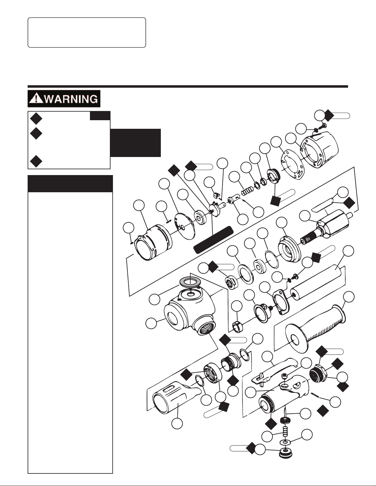
Index Key
No. Part # Description
1 01790 Screw (4)
2 01791 Washer (6)
3 07123 Governor Cover
4 07129 Gasket
5 07126 Governor Bushing
6 50471 Spring Holder
7 95611 Spacer (6/pkg.)
8 07159 Governor Spring - 8,500
07175 Governor Spring - 11,000
9 50470 Pin
10 50463 Governor Valve
11 50938 Governor Pin (2)
12 50399 Governor Weight (2) - 8,500
50460 Governor Weight (2) - 11,000
13 07124 Governor Cage
14 01007 Bearing
15 07114 Rear Bearing Plate
16 01775 Pin
17 07118 Cylinder
18 01673 Pin
19 07107 Blade (5/pkg)
20 07104 Rotor
21 07120 Front Bearing Plate
22 01277 Shim Pack (3/pkg.)
23 02552 Bearing
24 07158 Spacer
25 07135 Rotor Nut
26 07157 Handle Grip
27 52093 Rod
28 50511 Screw (2)
29 07149 Clamp
30 01797 Exhaust Cover
31 01798 Felt Silencer
32 96304 Gasket
33 07161 Housing
34 07136 Grip
35 02658 Packing
36 02631 Nut
37 02626 Adjustment Bushing
38 01746 O-Ring
39 01089 Safety Throttle Lever
40 07141 Valve Body
41 07142 Bushing
42 01697 Inlet Bushing
43 01017 Pin
44 07168 Valve Stem Assembly
45 07145 Spring
46 07146 Packing
47 07147 Plug
(Includes 07142 Bushing)
KEY
Disc Sander
Air Motor and Machine Parts
Always operate, inspect and maintain this tool in accordance with the Safety Code for portable air
tools (ANSI B186.1) and any other applicable safety codes and regulations. Please refer to Dynabrade’s
Warning/Safety Operating Instructions for more complete safety information.
A
lways follow adhesive
manufacturers cleaning
and priming
r
ecommendations.
5
3
4
6
12
11
7
8
m
•
N
11
T
17
16
15
9 N•m
T
A
8
13
14
9
10
21
18
22
23
FT HAND THRE
LE
T
25
ADS
24
23 N•m
2
29
32
30
31
33
50 N•m
T
38
39
A
8
35
36
A
37
2
40
T
N•m
5
4
34
A
8
45
17 N•m
T
47
See reverse side for Accessories and Important Operating, Maintenance and Safety Instructions.
1
2
20
T
28
41
44
46
N•m
8
T
19
m
N•
8
45 N•m
T
O
1
42
A
43
A
6
O
1
27
26
2
Page 2

Important Operating, Maintenance and Safety Instructions
Carefully read all instructions before operating or servicing any Dynabrade®Abrasive Power Tool.
Warning: Hand, wrist and arm injury may result from repetitive work motion and overexposure to vibration.
Important: All Dynabrade Rotary Vane air tools must be used with a Filter-Regulator-Lubricator to maintain all warranties.
Operating Instructions:
Warning: Eye, face, respiratory, sound and body protection must be worn while operating power tools. Failure to do so may result in serious injury or death.
Follow safety procedures posted in workplace.
1. With power source disconnected from tool, securely fasten abrasive /accessory on tool.
2. Install air fitting into inlet bushing of tool. Important: Secure inlet bushing of tool with a wrench before attempting to install the air fitting to avoid
damaging valve body housing.
3. Connect power source to tool. Be careful not to depress throttle lever in the process.
4. Check tool speed with tachometer. If tool is operating at a higher speed than the RPM marked on the tool or operating improperly, the tool should be
serviced to correct the cause before use.
5. Air tools are not intended for use in explosive atmospheres and are not insulated for contact with electrical power sources. Sanding/Grinding certain
materials can create explosive dust. It is the employers responsibility to notify the user of acceptable dust levels. Sanding/Grinding can cause sparks
which can cause fires or explosions. It is the users responsibility to make sure the work area is free of flammable materials.
Maintenance Instructions:
1. Check tool speed regularly with a tachometer. If tool is operating at a higher speed than the RPM marked on the tool, the tool should be serviced to
correct the cause before use.
2. Some silencers on air tools may clog with use. Clean and replace as required.
3. All Dynabrade Rotary Vane air motors should be lubricated. Dynabrade recommends one drop of air lube per minute for each 10 SCFM (example: if the tool
specifications state 40 SCFM, set the drip rate of your filter-lubricator at 4 drops per minute).
Dynabrade Air Lube (P/N 95842: 1 pt. 473 ml.) is recommended.
4. It is strongly recommended that all Dynabrade rotary vane air tools be used with a Filter-Regulator-Lubricator to minimize the possibility of misuse due
to unclean air, wet air or insufficient lubrication. Dynabrade recommends the following: 11411 Air Line Filter-Regulator-Lubricator — Provides accurate
air pressure regulation, two-stage filtration of water contaminants and micro-mist lubrication of pneumatic components.
Operates 55 SCFM @ 100 PSIG has 1/2" NPT female ports.
5. Use only genuine Dynabrade replacement parts. To reorder replacement parts, specify the Model #, Serial #, and RPM of your machine.
6. A Motor Tune-Up Kit (P/N 96011) is available which includes assorted parts to help maintain motor and repair motor.
7. Mineral spirits are recommended when cleaning the tool and parts. Do not clean tool or parts with any solvents or oils containing acids, esters,
keytones, chlorinated hydrocarbons or nitro carbons.
Safety Instructions:
Products offered by Dynabrade should not be converted or otherwise altered
from original design without expressed written consent from Dynabrade, Inc.
• Important: User of tool is responsible for following accepted safety codes such as those published by the American National Standards Institute (ANSI).
• Operate machine for one minute before application to workpiece to determine if machine is working properly and safely before work begins.
• Always disconnect power supply before changing abrasive/accessory or making machine adjustments.
• Inspect abrasives/accessories for damage or defects prior to installation on tools.
• Please refer to Dynabrade’s Warning/Safety Operating Instructions Tag (Reorder No. 95903) for more complete safety information.
• Warning: Hand, wrist and arm injury may result from repetitive work, motion and overexposure to vibration.
Notice
All Dynabrade motors use the highest quality parts and metals available and are machined to exacting tolerances. The failure of quality pneumatic motors
can most often be traced to an unclean air supply or the lack of lubrication. Air pressure easily forces dirt or water contained in the air supply into motor
bearings causing early failure. It often scores the cylinder walls and the rotor blades resulting in limited efficiency and power. Our warranty obligation is
contingent upon proper use of our tools and cannot apply to equipment which has been subjected to misuse such as unclean air, wet air or a lack of
lubrication during the use of this tool.
Note: To reorder replacement parts, specify the Model #, Serial #, and RPM of your machine.
LIFETIME WARRANTY
To validate Dynabrade Lifetime Warranty, you must register each tool at: www.dynabrade.com. Registration of each tool at website is required.
Dynabrade will not honor Lifetime Warranty on unregistered tools. Please view the entire Lifetime Warranty Policy at www.dynabrade.com.
Model Motor Motor Air Inlet Maximum Air Flow Air Pressure Spindle Weight Length Height
Number hp (W) RPM Thread CFM/SCFM (LPM) PSIG (Bars) Thread Pound (Kg) Inch (mm) Inch (mm)
50304 1.2 (895) 8,500 1/2" NPT 4/32 (906) 90 (6.2) 5/8"-11 male 4 (1.8) 8 (203) 6 (152)
50307 1.2 (895) 11,000 1/2" NPT 5/36 (1,020) 90 (6.2) 5/8"-11 male 4 (1.8) 8 (203) 6 (152)
Additional Specifications: Hose Size 1/2" (13 mm) • Visit Dynabrade.com for your model’s vibration and sound data.
2
Page 3

Mounting Arrangement
50275 – 5" Back-up Pad Assembly, 12,500 RPM max.
• Hard density.
• Includes 50273 Flange Nut.
• Accepts abrasive discs with 7/8" center hole.
50272 – 5" Pad
50273 Flange Nut
Disassembly/Assembly Instructions — 4-1/2"–5" Vertical Disc Sander
Important: Manufactures warranty is void if tool is disassembled before warranty expires.
Notice: All of the special repair tooling referred to in these instructions can be ordered from Dynabrade. Please refer to this parts page for the
proper part identification.
Motor Disassembly:
1. Shut the air supply to the tool and disconnect the tool from the air supply hose.
2. Remove the 50273 Flange, the abrasive and the 50275 Backing Pad.
3. Use a 5mm hex key to remove the 07190 Screws (4), 07191 Washers (4), 07129 Gasket and the 07161 Governor Cover from the 07126 Housing.
4. Pull the air motor out of the 07126 Housing.
5. Hold the 07135 Rotor Nut stationary and remove the governor assembly by turning it clockwise. (Left Hand Threads)
6. Fasten the 96346 Bearing Separator (2") around the portion of the 07118 Cylinder that is closest to the 07114 Rear Bearing Plate.
7. Position the motor assembly with the separator in the 96232 Arbor Press (#2) so that the threaded spindle of the 07104 Rotor is pointing down.
8. Use a 3/16" dia. flat end drive punch as a press tool along with the arbor press to push the rotor out of the 01007 Bearing.
9. Use the 96214 Bearing Removal Tool to remove the 01007 Bearing from the 07114 Bearing Plate.
10. Hold the vane slot portion of the 07104 Rotor in a vise with aluminum or bronze jaws, and remove the 07135 Rotor Nut by turning it counterclockwise.
11 Remove the 07120 Bearing Plate, 02552 Bearing and the 01277 Shims from the rotor.
Motor Disassembly Complete.
Valve Disassembly:
1. Remove the 07147 Plug by turning it counterclockwise.
2. Remove the 07146 Packing, the 07145 Spring, and the 07168 Valve Stem Assembly.
3. Remove the 01017 Pin and the 01089 Safety Throttle Lever.
Valve Disassembly Complete.
Muffler Disassembly:
1. Use a 5 mm hex key to remove the 50511 Screws (2), 01791 Washers (2), 07149 Clamp and the 01797 Exhaust Cover.
2. Remove the 01798 Felt Silencer and the 96304 Gasket.
Muffler Disassembly Complete.
Important: Clean and inspect all parts before assembling.
Muffler Assembly:
1. Install the 96304 Gasket onto the 07162 Housing.
2. Install the 01798 Felt Silencer into the 01797 Exhaust Cover and attach these to the 07162 Housing with the 07149 Clamp, 50511 Screws (2), and
the 01791 Washers (2).
Muffler Assembly Complete.
Valve Assembly:
1. Install the 07146 Packing onto the 07147 Plug.
2. Insert the 07145 Spring into the 07168 Valve Stem Assembly and install these into the 07141 Valve Body.
3. Secure the valve components in place with th 07147 Plug. (Torque to 17 N•m/150 in.- lbs.)
4. Install the 01089 Safety throttle Lever securing it in place with the 01017 Pin.
Valve Assembly Complete.
3
Page 4

Disassembly/Assembly Instructions – Vertical Disc Sander (cont.)
Motor Assembly:
1. Hold the vane slot portion of the 07104 Rotor in a vise with aluminum or bronze jaws so that the threaded spindle of the rotor is pointing up.
2. Select .003" (.08 mm) thickness in shims from the 01277 Shim Pack. Install the shims into the 07120 Bearing Plate and install the 02552 Bearing
nto the bearing plate.
i
3. Install the bearing/plate assembly onto the 07104 Rotor and secure the assembly in place with the 07135 Rotor Nut. (Torque to 23 N•m/200 in.- lbs.)
4. Use a .001" (.03 mm) feeler gauge to check the gap clearance between the bearing plate and the face of the vane slot portion of the rotor.
5. The gap clearance should be .001" (.03 mm) to .0015" (.04 mm). If the gap clarence needs adjustment repeat steps 2-4 adding or removing
shims as required.
6. Lubricate the 07107 Blades (5) with the 95842 Dynabrade Air Lube (10W/NR or equivalent) and install these into the vane slots in the motor.
7. Install the 07118 Cylinder over the 07104 Rotor so that the air inlet opening of the cylinder will line up with the air inlet opening in the
7114 Bearing Plate.
0
8. Use the 96244 Bearing Press Tool along with the 96232 Arbor Press to install the 01007 Bearing into the 07114 Bearing Plate. Rest the raised
outer diameter of the bearing press tool against the outer diameter of the 01007 Bearing and press the bearing into the bearing plate.
9. Use the raised inner diameter of the 96244 Bearing Press Tool so that it will rest against the inner diameter of the 01007 Bearing. Carefully press the
bearing/plate assembly onto the 07104 Rotor until it comes in contact with the cylinder. This will establish a snug fit between the bearing
plates and the cylinder.
10. Hold the 07135 Rotor Nut in vise with aluminum or bronze jaws so that the female threaded end of the rotor is pointing up.
11. Install the governor assembly onto the 07104 Rotor turning it counterclockwise. (Left Hand Thread) (Torque to 9 N•m/80 in.- lbs.)
12. Install the 07158 Spacer into the 04162 Housing.
13. Install the motor assembly into the 04162 Housing and orient the 01775 Pin to match the correct position of the governor cover.
14. Place the 07129 Gasket onto the 04162 Housing and then install the 07123 Governor Cover holding it in place with the 01790 Screws (4) and
the 01791 Washers (4). (Torque to 8 N•m/70 in.lbs.)
15. Install the 50275 Backing Pad, the abrasive and the 50273 Flange Nut.
Motor Assembly Complete.
Tool Assembly Complete.
Optional Accessories
Dynaswivel
Swivels 360° at two locations which
allows an air hose to drop straight to
the floor, no matter how the tool is held.
• 95462 1/2" NPT
Dynabrade Air Lube
• Formulated for pneumatic equipment.
• Absorbs up to 10% of its weight in water.
• Prevents rust and formation of sludge.
• Keeps pneumatic tools operating longer
with greater power and less down time.
95842: 1 pt. (473 ml)
95843: 1 gal (3.8 L)
96244 Bearing Press Tool
• This tool is designed to safely press a
bearing into a bearing plate and onto a shaft.
95823 – 21 mm Open-End.
®
96041 Motor Tune-Up Kit:
• Includes assorted parts to help maintain
and repair motor.
96232 #2 Arbor Press
• This arbor press is ideal for the disassembly
and assembly of air motors.
96346 Bearing Separator
• Use the separator to remove
gears and bearings.
96214 Bearing Removal Tool
• This tool is designed to pass through the
I.D. of the bearing plate and push against
the I.D. of the bearing.
REFERENCE CONTACT INFORMATION
American National Standards Institute (ANSI) • www.ansi.org
25 West 43 Rd St., 4th Floor • New York, NY 10036 • Tel: 1 (202) 293-8020
International Organization for Standardization (ISO)
www.iso.org • PO Box 56 • Ch-1211 Geneve 20, Switzerland
DYNABRADE, INC. www.dynabrade.com
8989 Sheridan Drive • Clarence, NY 14031-1419 • Phone: (716) 631-0100 • Fax: 716-631-2073 • International Fax: 716-631-2524
© DYNABRADE, INC., 2018
 Loading...