

Page 1
Parts Page Reorder No. PD11•26
Supersedes PD10•04
Effective July, 2011
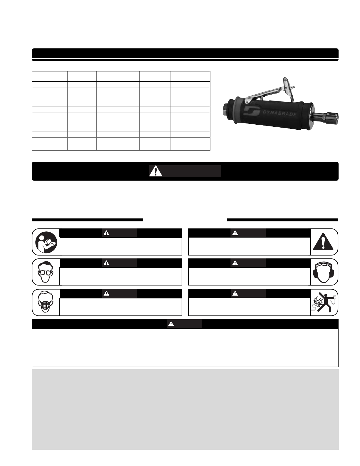
.4 hp Die Grinder
Ergo-Grip - Rear Exhaust
Air Tool Manual – Safety, Operation and Maintenance
Read and understand tool manual before
work starts to reduce risk of injury to
operator, visitors, and tool.
Eye protection must be worn
at all times, eye protection to
conform to ANSI Z87.1.
Respiratory protection to be used when
exposed to contaminants that exceed the
applicable threshold limit values required by law.
Air line hazard, pressurized supply lines and flexible
hoses can cause serious injury. Do not use damaged,
frayed or deteriorated air hoses and fittings.
SAVE THIS DOCUMENT, EDUCATE ALL PERSONNEL
SAFETY LEGEND
G
Ear protection to be worn when exposure to sound,
exceeds the limits of applicable Federal, State or
local statues, ordinances and/or regulations.
Read and understand this tool manual before operating your air tool. Follow all safety rules for the protection of operating personnel
as well as adjacent areas. Always operate, inspect and maintain this tool in accordance with the American National Standards
Institute (ANSI) Safety Code for Portable Air Tools – B186.1. For additional safety information, refer to Safety Requirements for the
Use, Care and Protection of Abrasive Wheels – ANSI B7.1, Code of Federal Regulation – CFR 29 Part 1910, European Committee for
Standards (EN) Hand Held Non-Electric Power Tools – Safety Requirements and applicable State and Local Regulations.
Some dust created by sanding, grinding, drilling, and other construction activities contain chemicals known to cause cancer, birth defects
or other reproductive harm. Some examples of these chemicals are:
• Lead from lead-based paints
• Crystalline silica from bricks and cement and other masonry products
• Arsenic and chromium from chemically treated lumber
Your risk from these exposures varies, depending on how often you do this type of work. To reduce your exposure to these chemicals: work in a well
ventilated area, and work with approved safety equipment, such as those dust masks that are specially designed to filter out microscopic particles.
Practice safety requirements. Work alert,
have proper attire, and do not operate tools under
the influence of alcohol or drugs.
FIND THE MOST CURRENT OFFERING OF SUPPORT DOCUMENTS AND ACCESSORIES AT WWW.DYNABRADE.COM
SAFETY INSTRUCTIONS
Carefully Read all instructions before operating or servicing any Dynabrade
®
Abrasive Power Tool. Products offered by Dynabrade are not to be
modified, converted or otherwise altered from the original design.
Tool Intent: .4 hp Die Grinder is ideal for deburring, deflashing, surface preparation, cleaning and finishing using the proper abrasive stones, abrasive
mounted wheels, molded abrasives, and carbide burrs.
Do Not use tool for anything other than its intended applications.
This power tool is not intended for use in potentially explosive atmospheres and is not insulated against contact with electrical power.
Training: Proper care, maintenance, and storage of your air tools will maximize their performance.
• Employer's Responsibility – Provide .4 hp Die Grinder operators with safety instructions and training for safe use of tools and accessories.
(continued on next page)
Model 48327
Model RPM Collet Style Muffler Insert Size
48201
25,000 3 Piece Extended 1/4" & 6 mm
48203
30,000 3 Piece Extended 1/4" & 6 mm
48325
25,000 3 Piece Standard 1/4" & 6 mm
48327
30,000 3 Piece Standard 1/4" & 6 mm
48341
30,000 3 Piece Overhose 1/8" & 3 mm
48345
30,000 4 Piece Standard 1/8" & 3 mm
48350
35,000 3 Piece Extended 1/8" & 3 mm
48355
35,000 3 Piece Extended 1/4" & 6 mm
48360
20,000 3 Piece Standard 1/4" & 6 mm
48365
20,000 4 Piece Standard 1/8" & 3 mm
48370
25,000 4 Piece Standard 1/8" & 3 mm
WARNIN
WARNING
WARNING
WARNING
WARNING
WARNING
WARNING
WARNING
Page 2
2
SAFETY INSTRUCTIONS
(Continued)
Accessory Selection:
• Abrasive/accessory RPM (speed) rating MUST be approved for AT LEAST the tool RPM rating.
• Before mounting an accessory, visually inspect for defects. Do not use defective accessories.
• Use only accessories of the correct shaft size for the collet (example: 1/4" shaft = 1/4" collet).
• Use only recommended accessories. Reference Dynabrade catalog and this tool manual.
• Follow tool specifications before choosing size and type of accessory.
• Only use recommended fittings and air line sizes. Air supply hoses and air hose accessories must have a minimum working pressure of 150 PSIG
(10 Bars) or 150 percent of the maximum pressure produced in the system, whichever is higher. (See tool Machine Specifications table.)
OPERATING INSTRUCTIONS
Warning: Always wear personal protective equipment. Operator of tool is responsible for following: accepted eye, face, respiratory, hearing and body protection.
Caution: Hand, wrist and arm injury may result from repetitive work, motion and overexposure to vibration.
• Keep hand and clothing away from working end of the air tool.
• Working end of tool has a potential of cutting and severing.
Operation: Be sure that any loose clothing, hair and all jewelry is properly restrained.
• Secure inlet bushing on air tool with a wrench before attempting to install the air fitting to avoid damaging housing assembly.
• BEFORE MOUNTING AN ACCESSORY, after all tool repairs and whenever a .4 hp Die Grinder is issued for use, check tool RPM (speed) with tachometer
with air pressure set at 90 PSIG while the tool is running. If tool is operating at a higher speed than the RPM marked on the tool housing, or operating
improperly, the tool must be serviced and corrected before use.
Caution: Tool RPM must never exceed abrasive/accessory RPM rating. Check accessory manufacturer for details on maximum operating speed or special
mounting instructions. Improper mounting of an accessory may cause excessive vibration levels or damage the accessory. Make sure no one is in the
unguarded plane of the accessory. Run tool for 1 minute of operating speed in a protected area.
• Connect air tool to power source. Be careful NOT to depress throttle lever in the process. Do not expose air tool to inlet pressure above 90 PSIG or (6.2 Bars).
Caution: After installing the accessory, before testing or use and/or after assembling tool, the .4 hp Die Grinder must be started at a reduced speed to check
for good balance. Gradually increase tool speed. DO NOT USE if tool vibration is excessive. Correct cause, and retest to insure safe operation. Test tool at
its free speed (RPM) in a protected area for at least one minute before applying the tool to the work.
• Release throttle lever when air supply is interrupted.
• Make sure that work area is uncluttered, and visitors are at a safe range from the tools and debris.
• Air tools are not intended for use in explosive atmospheres and are not insulated for contact with electric power sources.
• Use a vise or clamping device to hold work piece firmly in place.
• Do not apply excessive force on tool or apply “rough” treatment to it.
• Always work with a firm footing, posture and proper lighting.
• Ensure that sparks and debris resulting from work does not create a hazard.
• Tool is rear exhaust, exhaust may contain lubricants, vane material, bearing grease, and other materials flushed thru the tool.
Warning: Grinding certain materials can create explosive dust. It is the employers responsibility to notify the user of acceptable dust levels.
• Grinding can cause sparks which can cause fires or explosions. It is the users responsibility to make sure the work area is free of flammable materials.
• DO NOT USE cut-off wheels or router bits on this tool.
• Always use dust extraction or suppression systems and personal protective equipment which are suitable for the materials being processed.
Report to your supervisor any condition of the tool, accessories, or operation you consider unsafe.
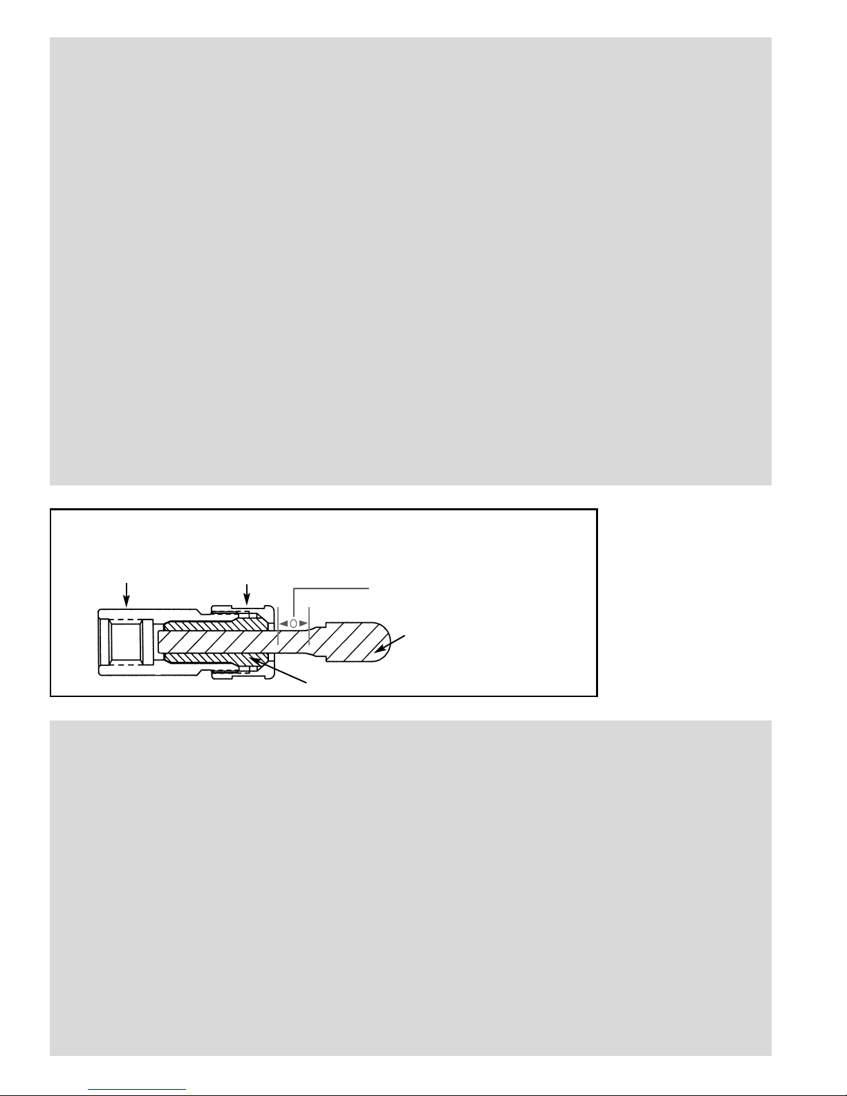
PROPER MOUNTING PROCEDURE
With Power Source Disconnected from the Tool, Mount Recommended Accessory
Collet Cap
Burr/Mounted Wheel
Collet Insert
Collet Body
Mount Wheel/Burr Mandrel
Fully Inserted into Collet Insert.
Excessive Overhang Reduces Bit MOS,
Refer to ANSI B7.1 Standards
Note: Intended for general
reference use only. Always refer
to ANSI B7.1, B186.1 and EN
792 for detailed requirements.
Bit Gripping Length: Bit should be
inserted no less than 1" (13mm) into
the collet insert.
Page 3
➤
Maintenance Instructions
Important: To keep tool safe a Preventative Maintenance Program is recommended whenever portable power tools are used. The program should include
inspection of air supply lines, air line pressure, proper lubrication and repair of tools. Refer to ANSI B186.1 for additional maintenance information.
•
Use only genuine Dynabrade replacement parts to ensure quality. To order replacement parts, specify Model#, Serial# and RPM of your air tool.
•
It is strongly recommended that all Dynabrade rotary vane air tools be used with a Filter-Regulator-Lubricator to minimize the possibility of misuse due to
unclean air, wet air or insufficient lubrication. Dynabrade recommends the following: 10681 Air Line Filter-Regulator-Lubricator — Provides accurate air
pressure regulation, two-stage filtration of water contaminants and micro-mist lubrication of pneumatic components. Delivers up to 55 SCFM/1,558 LPM
@ 145 PSIG/9.7 Bar (Max. Air Temperature of 140˚F/60˚ C) Note: Two (2) 3/8" NPT Reducer Bushings are included.
•
Dynabrade recommends one drop of air lube per minute for each 20 SCFM (example: if the tool specification states 40 SCFM, set the drip rate on the
filter-lubricator to 2 drops per minute). Dynabrade Air Lube (P/N 95842: 1 pt 473 ml) is recommended.
Specific Routine Preventative Maintenance - 20,000, 25,000 and 30,000 RPM Governed Tools: Check free speed tool using a tachometer without accessory
mounted. This governor controlled die grinder should be speed checked every 20 hours of use or weekly, whichever occurs more frequently after maintenance or repair.
•
DO NOT disassemble the governor for any reason. Reorder correct speed – governor assembly (See Assembly Breakdown) and recheck free speed of
tool with a tachometer.
Specific Routine Preventative Maintenance - 35,000 RPM Non-Governed Tools:
•
Check free speed of tool regularly using a tachometer without the abrasive accessory mounted. After all tool repairs and whenever a .4 hp Die Grinder is
issued for use, check tool RPM (speed) with tachometer with air pressure set at 90 PSIG while the tool is running. If tool is operating at a higher speed
than the RPM marked on the tool housing, operating improperly or demonstrates unusual vibration, the tool must be serviced and corrected before use.
Routine Preventative Maintenance
•
Inspect accessories before mounting. Do not mount accessories that are damaged or nicked.
•
Check accessory - speed rating. Rating on accessory must be greater than the tool speed marked on the housing.
•
If accessory breakage occurs, investigate to determine the cause and correct before issuing tool for work.
•
Mineral spirits are recommended when cleaning the tool and parts. Do not clean tool or parts with any solvents or oils containing acids, esters, ketones,
chlorinated hydrocarbons or nitro carbons.
•
DO NOT clean or maintain tools with chemicals that have a low flash point (example: WD-40
®
).
•
A Motor Tune-Up Kit (P/N 96541) is available which includes high wear and medium wear motor parts.
•
Air tool markings must be kept legible at all times, if not, reorder housing and replace. User is responsible for maintaining specification information
i.e.: Model #, S/N, and RPM. (See Assembly Breakdown)
•
Blow air supply hose out prior to initial use.
•
Visually inspect air hoses and fittings for frays, visible damage and signs of deterioration. Replace damaged or worn components.
•
Refer to Dynabrade's Warning/Safety Operating Instructions Tag (Reorder No. 95903) for safety information.
After maintenance is performed on tool, add a few drops of Dynabrade Air Lube (P/N 95842) to the tool inlet and start the tool a few times to lubricate air motor.
Check for tool vibration before mounting abrasive wheel accessory.
Handling and Storage:
•
Use of tool rests, hangers and/or balancers is recommended.
•
Protect tool inlet from debris (see Notice on Page 7).
•
DO NOT carry tool by air hose or near the tool throttle lever.
•
Protect accessories from exposure to water, solvents, high humidity, freezing temperature and extreme temperature changes.
•
DO NOT USE accessories that have been dropped or show signs of cracks, nicks or other defects.
•
Store accessories in protective racks or compartments to prevent damage.
3
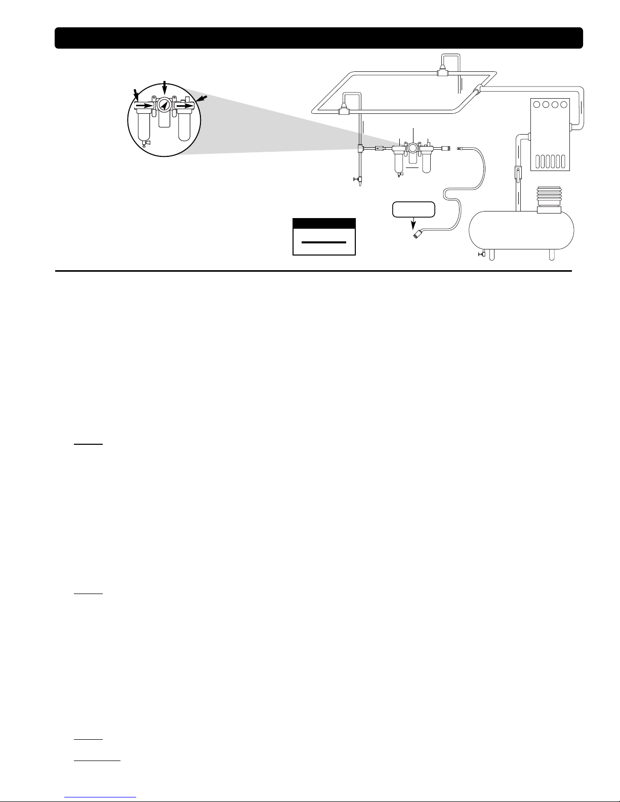
Air System
Filter
Regulator
Lubricator
90 PSIG
(6.2 Bar)
To Tool Station
Closed Loop Pipe System
(Sloped in the direction of air flow)
Ball
Valve
Ball
Valve
Filter
Regulator
Lubricator
Air Flow
Drain
Valve
Drain
Valve
Air Tool
Air Compressor
and Receiver
Drain Valve
Air Hose
90 PSIG MAX
(6.2 Bar)
Air Flow
Refrigerated
Air Dryer
1 DROP/MIN.
20 SCFM
LUBRICATOR SETTING
•
Dynabrade Air Power Tools are designed to operate at
90 PSIG (6.2 Bar) maximum air pressure at the tool inlet,
when the tool is running. Use recommended regulator
to control air pressure.
•
Ideally the air supply should be free from moisture. To
facilitate removing moisture from air supply, the installation
of a refrigerated air dryer after the compressor and the use
of drain valves at each tool station is recommended.
➤
➤
➤
➤
➤
Page 4

Adhesive: A8= Loctite #567
A
10
= Loctite #243
Torque: N•m x 8.85 = In. - lbs.
Oil: O
1
= Air Lube
O
A
T
KEY
.4 hp Die Grinder
Complete Assembly – All Models
4
Models:
48201, 48203, 48325
48327, 48341, 48345
48350, 48355, 48360
48365, 48370
1 01484 Collet Cap
2 Collet Insert
01495 1/8"
01485 1/4"
01496 3 mm
01497 6 mm
3 01435 Collet Body
4 51098 Collet Nut
5 51107 Collet Cap
6 51105 Collet Body
7 01489 Rear Exhaust Cover
8 01547 Collar
9 01580 Felt Seal
10 02649 Bearing
11 54551 Shim - .076"
12 54543 Shim - .025"
13 54544 Shim - .05"
14 01478 Front End Plate
15 50767 Pin (2)
16 01479 Spacer
17 01480 Vane Set (4/Pkg.) As Req.
18 45290 Rotor
19 01476 Cylinder
20 02673 Rear Bearing Plate
21 02696 Bearing
22 96077 O-Ring
23 Governor Assembly
45270 20,000 RPM (Yellow)
45271 25,000 RPM (Red)
45272 30,000 RPM (Green)
24 45276 Filter Cage
25 45278 Filter
26 45250 Housing Core
27 45257 Throttle Bushing
28 97045 Pin
29 45263 Safety Throttle Lever
30 97060
Pin
31 Exterior Housing (Laser Etched)
45209 Model - 48201
45210 Model - 48203
45201 Model - 48325
45202 Model - 48327
45217 Model - 48341
45218 Model - 48345
45219 Model - 48350
45220 Model - 48355
45221 Model - 48360
45231 Model - 48365
09707 Model - 48370
32 01464 Seal (2)
33 58365 Tip Valve
34 01468 Spring
35 01564 Air Control Ring
36 95711 Retaining Ring
37 01486 Felt Silencer (4)
38 96065 O-Ring
39 01446 Air Deflector
40 95620 Retaining Ring
41 01578 Inlet Adapter Assembly
42 95438 O-Ring
43 94521 Muffler Base
44 94525 Felt Muffler
45 94524 Sintered Bronze Muffler
46 94522 Muffler Cap
47 95375 O-Ring
48 94526 Spacer
49 94523 Inlet Adapter Assembly
50 94535 Muffler Assembly
51 94520 Muffler Assembly
Index Key
No. Part # Description
1
2
3
4
10
11
22
23
24
25
26
27
28
30
29
31
36
37
38
39
40
43
42
36
44
46
45
47
48
51
50
32
33
34
35
12
13
14
15
16
18
17
19
15
20
21
5
2
6
7
8
9
A
8
28 N•m
T
.5 - .9 N•m
T
3 - Piece Collet
96076 12 mm Wrench
95262 14 mm Wrench
4 - Piece Collet
96031 7/16" Wrench
96032 11/16" Wrench
3 - Piece Collet Assy.
50080 1/4" Insert
4 - Piece Collet Assy.
51121 1/8" Insert
51124 1/4" Insert
A
10
1.7 - 2.3 N•m
T
A
8
28 N•m
T
A
8
28 N•m
T
A
8
O
1
O
1
41
49
Governors are Non-serviceable.
Used on 20,000 - 30,000 RPM models ONLY.
Page 5

Disassembly/Assembly Instructions
Important: The Dynabrade Pneumatic Power Tool Lifetime Warranty Policy does NOT cover normally wearable parts and products. Before servicing this tool
please contact Dynabrade Inc. or a Dynabrade Subsidiary for information regarding the Dynabrade Pneumatic Power Tool Lifetime Warranty Policy.
Notice: To avoid damaging the motor housing, use the Special Repair Tool that is designed for disassembly and assembly of these die grinders.
See page 8 for a complete list of available repair tools.
Disconnect the die grinder from the air supply.
Motor Disassembly:
1. Secure the air inlet adapter of the die grinder in a vise with aluminum or bronze jaws so that the collet assembly is pointing up.
2. Loosen the collet cap and remove the insert tool, cap and insert.
3. Use the 50971 Lock Ring Tool to remove the rear exhaust cover. Turn counterclockwise.
Note: One of two things will occur.
A. The rear exhaust cover will loosen. If this occurs, remove the rear exhaust cover and remove the air motor assembly by pulling the motor out of the
housing. Remove the filter cage and filter. Insert the hex end of the 96402 Special Repair Tool into the hex socket in the bottom of the housing.
Use an adjustable wrench to loosen the housing from the air inlet adapter.
B. The air inlet adapter will loosen. If this occurs, remove the air inlet adapter and valve components.
Remove the 2 valve seals (Fig.1). Insert the “Tear-Drop End” of the 96402 Special Repair Tool into the air inlet of the housing. Place the hex end of the
special repair tool in a vise with aluminum or bronze jaws so that the housing is pointing up (Fig.2 & 3). Use the 50971 Lock Ring Tool to remove the rear
exhaust cover (Fig.4). Turn counterclockwise.
FOR MODELS WITH GOVERNORS: 48201, 48203, 48325, 48327, 48341, 48345, 48360, 48365 and 48370
4. Carefully secure the wrench flats of the collet body in a vise with aluminum or bronze jaws so that the governor assembly is pointing up. Use a slot blade
screwdriver to remove the governor. LEFT HAND THREAD: Turn clockwise. Note: The governor assembly is not serviceable. If a governor fails it must be
replaced as a complete assembly.
FOR ALL MODELS:
5. Fasten the 96346 Bearing Separator (2") around the portion of the 01476 Cylinder that is closest to the 02673 Rear Bearing Plate. Place the bearing
separator and the motor in the 96232 Arbor Press (#2) so that the collet body is pointing down.
6. Use a 5/32" (4 mm) diameter flat end drive punch as a press tool to push the rotor out of the 02696 Bearing.
7. Remove the cylinder and vanes.
8. Use the 5/32" (4 mm) diameter flat end drive punch to push the 02696 Bearing out of the 02673 Rear Bearing Plate.
9. Secure the body of the rotor in a vise with aluminum or bronze jaws and remove the 01435 Collet Body. Turn counterclockwise.
10. Remove the 01478 Front Bearing Plate, 02649 Bearing, shims, and 01479 Spacer.
Motor Disassembly Complete.
Important: Clean and Inspect Parts for Wear or Damage Before Assembling.
(continued on next page)
5
96402 - Special Repair Tool
“Tear-Drop End” Hex End
1234
Page 6

1. Secure the body of the rotor in a vise with aluminum or bronze jaws and install the 01479 Spacer onto the rotor.
2. Select .003" (.08 mm) shim thickness from the 54529 Shim Pack and install these into the 01478 Front Bearing Plate.
3. Install the 02649 Bearing into the front bearing plate and install these onto the rotor.
4. Install the 01435 Collet Body onto the 45290 Rotor. (Torque to 17 N•m/150 in. lbs.)
5. Use a .001" (0.3 mm) thick feeler gauge to check the clearance between the bearing plate and the face of the rotor.
6. Clearance should be .001"-.0015" (0.3-0.4 mm). Note: If the clearance needs adjustment, repeat steps 2-6. Add or remove shims as required.
7. Use Dynabrade Air Lube 95842 (10W/NR or equivalent) to lubricate the 01480 Vanes. Install the vanes into the rotor.
8. Install the 01476 Cylinder and the 02673 Rear Bearing Plate so that the air inlet openings align with each other.
9. Position the 02696 Bearing onto the bearing journal of the rotor.
10. Use the RAISED CENTER of the 96242 Bearing Press Tool and the arbor press to install the 02696 Bearing onto the rotor and into the 02673 Rear
Bearing Plate. IMPORTANT: Carefully press the bearing onto the rotor and into the plate until the plate just touches the cylinder. This will establish a snug
fit between the bearing plates and the cylinder.
FOR MODELS WITH GOVERNORS: 48201, 48203, 48325, 48327, 48341, 48345, 48360, 48365 and 48370
11. Apply a small amount of the Loctite #243 (or equivalent) to the threads of the governor assembly and carefully install the governor onto the rotor.
LEFT HAND THREAD: Turn counterclockwise. (Torque to 0.5 - 0.9 N•m/5 - 8 in. lbs.)
FOR ALL MODELS:
12. Install the filter onto the filter cage, and install these into the housing.
13. Carefully slide the motor assembly into the housing.
14. Install the 01580 Felt Silencer onto the front of the air motor.
15. Apply a small amount of Loctite #567 (or equivalent) to the threads of the rear exhaust cover and install the cover onto the housing. (Torque to 28
N•m/250 in. lbs.)
Motor Assembly Complete. Tool Assembly Complete. Please allow 30 minutes for adhesives to cure before operating tool.
Important: Before operating, place 2-3 drops of Dynabrade Air Lube (P/N 95842) directly into air inlet with throttle lever depressed. Operate tool for 30 seconds
to determine if tool is operating properly and to allow lubricating oils to properly penetrate motor. Motor should now be tested for proper operation at 90 PSIG. If
motor does not operate properly or operates at a higher RPM than marked on the tool, the tool should be serviced to correct the cause before use.
Loctite®is a registered trademark of Loctite Corp.
6
Lifetime Warranty
All Dynabrade portable pneumatic power tools are rigorously inspected and performance tested in our factory before shipping to our
customers. If a Dynabrade tool develops a performance problem and an inherent defect is found during normal use and service, Dynabrade
will warrant this tool against defects in workmanship and materials for the lifetime of the tool. Upon examination and review at our factory,
Dynabrade shall confirm that the tool qualifies for warranty status, and will repair or replace the tool at no charge to the customer. Normally
wearable parts and products are NOT covered under this warranty. Uncovered items include bearings, contact wheels, rotor blades, regulators,
valve stems, levers, shrouds, guards, O-rings, seals, gaskets and other wearable parts. Dynabrade’s warranty policy is contingent upon proper
use of our tools in accordance with factory recommendations, instructions and safety practices. It shall not apply to equipment that has been
subjected to misuse, negligence, accident or tampering in any way so as to affect its normal performance. To activate lifetime warranty,
customer must register each tool at www.dynabrade.com. Dynabrade will not honor lifetime warranty on unregistered tools. A one-year
warranty will be honored on all unregistered portable pneumatic power tools. Lifetime warranty applies only to portable pneumatic tools
manufactured by Dynabrade, Inc. in the USA. Lifetime warranty applies only to the original tool owner; warranty is non-transferable.
Machine Specifications
Model Motor Motor Sound Maximum Air Flow Collet Air Pressure Weight Length Height
Number hp (W) RPM Level SCFM (LPM) Insert Size PSIG (Bars) Pound (kg) Inch (mm) Inch (mm)
48201 .4 (298) 25,000 76 dB(A) 23 (651) 1/4" & 6 mm 90 (6.2) .9 (.4) 8 (202) 1.7 (44)
48203 .4 (298) 30,000 78 dB(A) 23 (651) 1/4" & 6 mm 90 (6.2) .9 (.4) 8 (202) 1.7 (44)
48325 .4 (298) 25,000 79 dB(A) 23 (651) 1/4" & 6 mm 90 (6.2) .9 (.4) 8 (202) 1.7 (44)
48327 .4 (298) 30,000 79 dB(A) 23 (651) 1/4" & 6 mm 90 (6.2) .9 (.4) 6.5 (166) 1.7 (44)
48341 .4 (298) 30,000 79 dB(A) 23 (651) 1/8" & 3 mm 90 (6.2) .9 (.4) 6.5 (166) 1.7 (44)
48345 .4 (298) 30,000 79 dB(A) 23 (651) 1/8" & 3 mm 90 (6.2) .9 (.4) 6.5 (166) 1.7 (44)
48350 .4 (298) 35,000 80 dB(A) 23 (651) 1/8" & 3 mm 90 (6.2) .9 (.4) 8 (202) 1.7 (44)
48355 .4 (298) 35,000 80 dB(A) 23 (651) 1/4" & 6 mm 90 (6.2) .9 (.4) 8 (202) 1.7 (44)
48360 .4 (298) 20,000 76 dB(A) 23 (651) 1/4" & 6 mm 90 (6.2) .9 (.4) 6.4 (162) 1.7 (44)
48365 .4 (298) 20,000 76 dB(A) 23 (651) 1/8" & 3 mm 90 (6.2) .9 (.4) 6.4 (162) 1.7 (44)
48370 .4 (298) 25,000 79 dB(A) 23 (651) 1/8" & 3 mm 90 (6.2) .9 (.4) 6.4 (162) 1.7 (44)
Additional Specifications: Air Inlet Thread 1/4" NPT • Hose I.D. 1/4" (6 mm)
Sound Level is the pressure measurement according to the method outlined in ISO regulation ISO-15744
Page 7

This service chart is published as a guide to expectant life of component parts. The replacement levels are based on average tool
usage over one year. Dynabrade Inc. considers one year usage to be 1,000 hours.
Preventative Maintenance Schedule
.4 hp Die Grinder – All Models
Tune-Up Kit
Part No. 96541
LEGEND
T Included in Tune-Up Kit
X Type of wear, no other
comments apply.
L Easily lost. Care during
assembly/disassembly.
D Easily damaged during
assembly/disassembly.
R Replace each time tool is
disassembled.
7
Note: Please refer to page 4 of tool manual for specific part number.
Notice
All Dynabrade motors use the highest quality parts and metals available and are machined to exacting tolerances. The failure of quality pneumatic
motors can most often be traced to an unclean air supply or the lack of lubrication. Air pressure easily forces dirt or water contained in the air supply into
motor bearings causing early failure. It often scores the cylinder walls and the rotor blades resulting in limited efficiency and power. Our warranty obligation
is contingent upon proper use of our tools and cannot apply to equipment which has been subjected to misuse such as unclean air, wet air or a lack of
lubrication during the use of this tool.
Parts Common to all Models:
Index Part Description Number High Wear Medium Wear Low Wear Non-Wear
# Number Required 100% 70% 30% 10%
1 01484 Collet Cap 1 X
2
See Note Collet Insert 1 X
3 01435 Collet Body 1 X
4 51098 Collet Nut 1 X
5 51107 Collet Cap 1 X
6 51105 Collet Body 1 X
7 01489 Rear Exhaust Cover 1 X
8 01547 Collar 1 X
9 01580 Felt Seal 1 T, R
10 02649 Bearing 1 T, R
11 54551 Shim - .0025" As Req. T, R
12 54543 Shim - .001" As Req. T, R
13 54544 Shim - .002" As Req. T, R
14 01478 Front End Plate 1 X
15 50767 Pin 1 D
16 01479 Spacer 1 T
17 01480 Vane Set (4/Pkg.) As Req. T, R
18 45290 Rotor 1 X
19 01476 Cylinder 1 X
20 02673 Rear Bearing Plate 1 X
21 02696 Bearing 1 T, R
22 96077 O-Ring 1 T
23
See Note Governor Assembly 1 D
24 45276 Filter Cage 1 X
25 45278 Filter 1 T, R
26 45250 Housing Core 1 X
27 45257 Throttle Bushing 1 T
28 97045 Pin 1 T
29 45263 Safety Throttle Lever 1 D
30 97060 Pin 1 T
31
See Note Exterior Housing 1 X
32 01464 Seal 1 T
33 58365 Tip Valve 1 T
34 01468 Spring 1 T
35 01564 Air Control Ring 1 L
36 95711 Retaining Ring 1 T, R
37 01486 Felt Silencer 1 T, R
38 96065 O-Ring 1 T
39 01446 Air Deflector 1 X
40 95620 Retaining Ring 1 T
41 01578 Inlet Adapter Assembly 1 X
42 95438 O-Ring 1 T
43 94521 Muffler Base 1 X
44 94525 Felt Muffler 1 T, R
45 94524 Sintered Bronze Muffler 1 T, R
46 94522 Muffler Cap 1 X
47 95375 O-Ring 1 T
48 94526 Spacer 1 X
49 94523 Inlet Adapter Assembly 1 X
Page 8

DYNABRADE, INC.,
8989 Sheridan Drive •Clarence, NY 14031-1419 •Phone: (716) 631-0100 •Fax: 716-631-2073 •International Fax: 716-631-2524
DYNABRADE EUROPE S.àr.l.,
Zone Artisanale •L-5485 Wormeldange—Haut, Luxembourg •Telephone: 352 76 84 94 1 •Fax: 352 76 84 95 1
© DYNABRADE, INC., 2011 PRINTED IN USA PD11.26_07/11
Visit Our Web Site: www.dynabrade.com Email: Customer.Service@Dynabrade.com
Optional Accessories
Dynabrade Air Lube
•
Formulated for pneumatic equipment.
•
Absorbs up to 10% of its weight in water.
•
Prevents rust and formation of sludge.
•
Keeps pneumatic tools operating longer
with greater power and less down time
.
Part No. 95821: 4oz. (118 ml)
Part No. 95842: 1pt. (473 ml)
Part No. 95843: 1gal. (3.8 L)
Composite-Style Coupler
•
Lightweight 1.4 oz. (.05 Kg), non-marring
composite material.
•
Easy connect/disconnect by single
push-button action.
•
Shock-proof, low-vibration, crush-resistant.
Part No. 94960 – 1/4" Female NPT
Part No. 94980 – 1/4" Male NPT
Male Plug
•
Provides up to twice the air flow
compared to standard plug design.
•
Plug has “ported” design to prevent
“starving” of the air tool.
Part No. 95675
Lock Ring Wrench
•
Has a 3/8" square socket for use with
3/8" drive; breaker bar, ratchet head, or
torque wrenches.
Part No. 50971
Bearing Separator
•
Use the separator to remove
gears and bearings.
Part No. 96346
Press Tool
•
Used to install bearings.
Part No. 96242
FIND THE MOST CURRENT OFFERING OF SUPPORT DOCUMENTS AND ACCESSORIES AT WWW.DYNABRADE.COM
Reference Contact Information
1. American National Standards Institute – ANSI 3. European Committee for Standardization
25 West 43
rd
Street Rue de Stassart 36
Forth Floor B - 1050 Brussels, Belgium
New York, NY 10036
Tel: 1 (212) 642-4900
Fax: 1 (212) 398-0023
2. Government Printing Office – GPO 4. Power Tool Institute, Inc.
Superintendent of Documents P.O. Box 818
Attn. New Orders Yachata, Oregon 97498-0818
P.O. Box 371954 Tel: 1 (503) 547-3185
Pittsburgh, PA 15250-7954 Fax: 1 (503) 547-3539
Tel: 1 (202) 512-1803
Motor Tune-Up Kit
•
Includes assorted parts to help
maintain and repair motor.
Part No. 96541
Drop-In Motor
•
Allows quick and easy replacement.
•
No motor adjustments needed.
Part No. 45286 – Models: 48201
48203, 48325
48327, 48341
48350, 48355
48360
Part No. 45288 – Model: 48345
48365, 48370
®
DYNABRADE
 Loading...