


SERIAL
This
number
tioned
tions concerning Dynakit.
NUMBER
. I
15350075
mustbemen-
in
all communica-
STEREO
CONTROL
INSTRUCTIONS
ASSEMBLY
OP.ERATION
AMPLIFIER.
FOR
AND
,..
Patented
Price
$1.00
086315

SPECIFICATIONS
• •••1)
5
6
7
9
Tone
Control
Sensitivity
Rated
Power
Frequency
Power
1M
Hum
Tube
Complement:
Silicon
Power
Consumption:
Special
Inputs:
Outputs:
Controls:
Range:
Output:
Output:
Response:
Response:
Distortion:
and
Noise:
Diodes:
Features:
for
7 pairs:
magnetic
Ceramic
(100,000
Constant
loudspeaker
output,
Selector, Volume, Balance, Bass,
Stereo-Mono
Switch,
± 12
2.5 mv
RIAA
magnetic
phono high level (50,000
phono;
ohms);
provision for
level
outputs,
NAB
71j2
radio, tape,
tape
output,8and
center-channel
headphone
Switch, Loudness
Filter
Switch, Power Switch.
dbat50
at
cps
and
15 kc.
tape
head, 4 mvatlow level
phono
i.p.s.
spare
low level,
ohms);
tape
head
(250,000
ohms)
16 ohm
loudspeaker
connection.
Treble,
Compensation
magnetic
phono, 1 voltathigh level inputs.
35
watts
Music
continuous, 45
Power
(both
watts
channels).
IHF
± 0.25dbfrom 20 cpsto20 kc.
to
20 kc
20 cps
without
within 1dbof 17.5
than
Less
Less
1%at17.5
than
0.2%onany
exceeding 1%
watts
(each
watts
(each
inputataverage
distortion
channel)
channel)
.
.
listening levels.
70
db
below
rated
outputonlow level inputs.
db
downonhigh
80
12AX7/ECC83
6BQ5/EL-84/7189
500
MA,
1000
level inputs.
(2),
(4).
PIV
7199
(2).
(2),
110 watts, 120 volts 60 cycle AC,or120/240volts
50/60
cycle
AC
with
optional
PB-028
power transformer.
Attractive
front
outlets; provision for
center-channel level control;
output;
encapsulating
quietest
Champagne-gold anodized
panel
and
die-cast knobs; 2ACconvenience
headphone
power
transformer
material
for coolest,
operation.
aluminum
output
center
or
speaker
sealedinspecial

INSTRUCTIONS
THE
DYNAKIT
The
SCA-35isa
amplifier combination which servesasa control
various program sources
radio.
The
SCA-35
desired, modification of
sound
source,
nections for loudspeakers
The
made on
vided.
the program source
tween these components.
connection of loudspeakers to
inputs
tom row for
operation of
viding
use of
switches
of
listening pleasure.
.Jeledor
•
permits
"phono"
will
extends
switch
being played,
single channel signal
playing monophonic recordings with a stereo cartridge,
"mono"
ponents
a monophonic station,
frequently eliminates noise
Volume
level of
settingofthe
loudspeakers
and/or
the
is
a specific
loudness level desired
knob pointer.
settingorvolume control, this should be
...
~e
..
itisswitched to
The
and
The
front
suitable
the
Rotationofthe
be
The
Clockwise rotation of
control is
played-you
If
the
witching from one
same loudness.
Beneath
and
connection of various types of program sources
the
back
shielded
outputsisused
the
panel
the
the
SCA-35 using
and
the
other
switches
Switch
use of
for example,
available to you.
stereo-mono switch
its
utility.
in
the
the
position eHminates
of the signal.
Control
the
signal
and
tuners.Itshould be recognized
not
sound
tuner,orother
the
high
quality
such
permits
change
panel
audio
equipment
right
FRONT PANEL CONTROLS
controls
SCA-35 simple
flexibility. Althoughitis possible to enjoy
volume control, knowledge of
Each
selector switchtothe
the
marked
For
"stereo"
"mono"
through
control will
the size of
related to
may
level.
inputtoanother,
volume control is
"loudness"
selection of
the
of volume;itprovides
and
through
cable'S
There
for
channel.
have
and
controls
of these will be described briefly.
input
start
the
stereo signal sources, leave the
position.
position of
through
mostofthe
When
the
"mono"
the
both
dependonthe
the
have a wide range of settings to give
Adjustment
without
input
stereo preamplifier
as
phonograph,
tonal characteristics of
headphones.
the
and
are
used
are
the
unit.
the
left channel,
been designed to
and
only
the
can
source. After switching to
record player,
beneath
When
the
both
loudspeakers. When
a stereo
and
volume control increases
the
regardtothe
equipment, has
there
FM
position of
distortion.
loudspeakers:
signals from
power levelatwhich music
should be
the
the
loudness switch.
is additional bass intro-
FOR
SCA-3S
the
program
several sockets proplugs
supplied
for connection be-
screw terminals for
The
upper
obvious while pro-
power
the selector switch
and
provide increased
marked
and
a mono source is
switch brings
vertical noise com-
tuneristuned
efficiency of
the
that
the
position of
its
setsothat
sound is close to
ASSEMBLY
STEREO
and
center
output
and
the
the
The
cartridges
position of
madetothe
for
tape
and
source
the
con-
with
row of
the
bot-
make
thf:
selector
function
positions
its
signal
this
the
to
switch
the
normal
the
the
own level
when
When
AND
OPERATION OF
CONTROL AMPLIFIER
into
duced
mid-pointorbelow.Athigh settings of
the
loudness switch has no effect.
tureisthat
frequencies
helps to correct for this.
music which
is
Balance
The
two loudspeakers, which helps
the
balance control to
the right speaker,
the
left.
to
the
Normally
the
mid-point
ming,
ponent
the
mid-point. Since
gradual
offsetting
When
off one
signals
reverse
not
wanted
Tone
The
the
with
bass control
response
is
at
counter-clockwise rotation gives
When
uation will improve
attenuation
can
benefit from bass boost.
whatever position
that
departures
user
should
tonal characteristic.
Beneath
isinthe
attenuating
This
scratchy
and
so on.
it
does
used
extremes of tonal correction.
Power
The
the
SCA-35onand
switched
warmup
for
the music when
the
human
at
low volume levels,
can
Control
balance control is used to equalize
Turningtothe
right.
the
(12
in
speaker
toleranceinthe
in
the
area
itinthis
rotatedtoeither
speaker
appear
track
Controls
bass
treble control affecting high frequencies,
without
12 o'clock. Clockwise rotation provides boost,
program
"filter" positionitgives a narrow
should be
records, excessive rumble, noisy radio broadcasts,
not
in
Switch
power switch has
outletonthe
in
of a mono
simultaneously.
and
the
should be used.
from
not
getinthe
the
tone controls is
both
used
By
attenuatingatboth
create
Conjunction with
after
ear
It
enhance
the
thus
making the sound source move to
right
balance control is centered whenitis in
o'clock),
efficiencies,inroom acoustics,
SCA-35
the
of rotation from 9 o'clockto3 o'clock,
region does
completely.
the two stereo channels
treble controls
low frequencies.
frequency discrimination when
sources
the
sound.Ifthere is boominess, bass
sounds
"flat"
high
and
with poor program material,
a shiftinoverall tonal balance.Itcan
off (along with
back
turning
the
volume control isatthe
the
volume control,
The
reason for this fea-
has decreased sensitivity to low
and
the
loudness switch
will
add
a fullness to low level
its
pleasure.
the
to
center
left will diminish
will move
but
differencesinprogram-
may
require a
effects of
extreme, the balance control cuts
This
tape
are
harshorstrident, treble
Some
These
best,
are
ofa corrective
habit
low frequencies simultaneously.
the
the
panel).
this
switch to
this
not
indicate abnormality.
canbeused
machine),
operateinsimilar fashion
Each
attenuation.
thin sounding
controls should be
butitshould be remembered
of listening to a corrected
the
filter switch. When
endsofthe
tone controls for
obvious function of turning
any
Allow
signalsatthe
the
sound.
the
control
and
of these gives "flat"
equipmentinthe
about
"power."
Turning
the
sound
sound source
andincom-
setting
are
if different
(such
as
the
two
and
the
pointer
atten-
material
set
nature;
band
and
response,
such
spectrum,
15 seconds
very
the
are
the
and
the
this
great
to
off
to
as
be
3

BACK
Phono
can
for use of all
choice of
magnetic
ular
if
high
be used.Ifyou
find
usingitin
magnetic
amplification
read
mine
dations
today
nectedtothe
the
yout
wire,inadditiontothe
tridge, from a
the
desirabletomake
ortoan
that
nel).Ifyou
the
tiontohear
Connections
Either
the
In
If
a record
be used.
magnetic
level model,
that
instructions
phono
phonograph,
grounding screw
the
you
stereo-mono
There
(1)
cartridge,or(3)
cartridgeisratedatmore
there
the
input
whether
for
its
many
of
there
is a
screwonthe
inputs.Ifsuchaground
ground
"earth"
phono
COlUlcct
wanttohear
the
PANEL
changerora professional
are
typesofphonograph
low level
cartridges
and
are
using
seems to
low level
may
be used.
without
which
its
manufacturer
connections
the
turntables
separate
thenitmay
pointonthe
on
further
ground.
cartridge
its
outputtoonly
switchonthe
program
CONNECTIONS
three
pairsofphono
magnetic
crystalorceramic
areofthe
the
high
a low level
be
phono
detriment
accompany
ground wire.
back
audio
the
ground
is a mono one,
sound
through
cartridge,
than
level
too
much
input,
This
to performance. Always
has
and
use.
and
panelofthe
wire is
be necessary to
signal cables from
turntable
SCA-35.
conectionstowater
through
front
both
type
turntable
inputs,
cartridges.
type.
low level type. However,
20 millivolts
magnetic
magnetic
amplification when
then
will reduce
the
cartridgetodeter-
any
special recommen-
record changers
This
not
motororarm
Normallyitis
thenitis suggested
one
input
both
paneltoits
loudspeakers.
allowing
Thereisa
(2)
high
level
Most
pop-
this
is a
input
should
cartridge
the
should
SCA-35 above
supplied
(either
channels,
mono posi-
high
level
the
total
made
be con-
connect
the
pipes
chan-
and
with
car-
not
turn
through
direction
unless
(1)
thenbyusing
the
balance
eliminate
cannotbeused
recording preamplifier.
Radio
output
stereophonic,
radio
inputofthe
connected
ortoonly
turn
sound
out
a
(or
for
to
made
Additional
typeofhigh
moreofaudio
back
orasecond
one
One cable
sound
control
The
SCA-35
Connections
Radio
canbeused
input
the
from
If
the
its
own provision for switching these,
both)
AM.
with
The
spare
electronics huil t
the
SCA-35,
will
come
through
of
two
expedients
canberemoved
the
will come
sound
tuners
either
one
stereo-mono
tuner
of the
Then
the
mono
canbeturnedtoeither
through
canbeused
for recording
which
with
then
its
and
the
right
SCA-35.Ifthe
with a
input.Ifone
switchtothe
both
speakers.
has
separate
radio
selection of
selector switchonthe
Inputs
input
of
level
input
signal. A second
in)ortuner
phonograph
the
track
recordedinthe
one
channel
is
used
from
the
position of
through
the
for
can
supply
the
left
output
output
tuncr
"Y"
connectortoboth
input
outputs
inputs
FMorAM
the
SCA-35 will
source which provides
which
the
both
unwanted
playing
withatape
SCA-35.Ifthe
for
tape
includes
stereo-mono
speakers,
extreme
channel.
recorded
one
voltormore
is COlmectedtothe
goestothe
is monophonic,itcan
is used,
mono
for
FM
and
SCA-35.
machine
maybeusedinthis
its
opposite
of
the
SCA-35
to
prevent
unwanted
or
deck which
tuncrisFM
radio
you
will have
position to receive
AM
and
you
may
the
spare
broadcasts
accommodate
(having
own preamplifier.
this:
chann*,
swit~)
(2)
The-
position to
tape,
but
has
audio
upper
lower
radio
inputs,
FM
with-
use
inputs
can
one
volt
play-
inpue
it
no
be
to
one
be
any
or
~
'
Tape
Connections
The
SCA-35
which has
withatape
If
the
machine
putisatarelatively
connected to
AMP."Ifthe
low
and
The
tape
required
Generally, when
mustbeconnected
(see
screwonthe
wire for lowest
connect
the
the
connectedtothe
Whatever
corded
Thus
tone
the recorder.
track
NAB
instructions
If
the
tape
the SCA-35tothe
phonographorfrom
tape
unaffectedbyvolume
you
controlstosuit,
In
the
tape
can
its
own
tape
deck
having
hasatape
the
inputofthe
machineisa
the
input
head
input
7%
i.p.s.
the
supplied
SCA-35.
hum.
machine
recorder
socket
is being
can
listentoa
special case whereitis
withamonophonic
be
used
either
amplifier, or
direct
output
playback
high
level.Inthis
SCA-35
deck
marked
has
tape
from a specific
(not
played
without
"From
very
equalization
head
input
with
tape
Tryitwith
has
a recording amplifier,
tape
the
tuner.
the
microphone
marked
through
and
program
affecting
withatape
playback
from
amplifier,
case
marked
only,
the
TAPE
high
amplification
for
tape
is used, a
point
on
deck)tothe
and
without
machine
tone
for recording from
The
high
input)
"To
TAPE
the
SCA-35 will be re-
controlsofthe
and
adjust
the
signal going
desiredtoplayamulti-
recording
machine
electronics, or
the
tape
then
the
this
output
"From
outputisvery
HD"
is
and
head
playback.
ground
the
tape
grounding
this
you
level
input
should
RECORD."
volume
on
all
head.
out-
TAPE
used.
the
wire
deck
ground
can
of
be
SCA.
and
into
tracks
Loudspeakers
The
SCA-35
the
most
cations
Generally
is
of
these
ances
used
canbeused
upper
shouldbeused
(marked
The
lower
on
N
terminals. However,itis possible to
speaker-asacenterorremote
Details
connect
coveredindetail
identical.Ifthisisnot
considerably
of
to
of
the
SCA-35
terminals
than
for
speakers
The
left
output
right
output
each
eitherofthe
on
headphones
In
any
sounds
the
correct
can
provide
inefficient
the
this
marked.
with
channel
HC")
speaker
strip
this use
music
between the
loudspeaker
loudspeaker
will be 8or16 ohms.
are
marked
will
accommodate
For
of 4 to 11 ohm ratings;
speakers
loudspeaker
strip. A
strip.
distorted,
localization of those sounds.
pair
with
one
and
the
should
Note
are
connected
two
speakers
are
to the
later.
systemitis
speakers
sufficient power to
systems.
to
determine
The
for
speakersofthese
a wider range of imped-
example,
from 12to20 ohms.
of wires,
wire going to
othertothe8or16ohm
that
given later.Itis also possible to
loudspeaker
possible, the
and
the8ohm
shouldbeconnected
such
the
be
similarly
the
extreme
together
shouldbeconnectedtothese
connect
speaker--·to
terminals, a
best
that
both
stereo
there
will be shifting of
in a way which is
drive
Check
speaker
the16ohm
as
by
the
its
impedance.
terminals
values,
output
# 18
lamp
common
connected
left
hand
a wire
a thiJ:d loud-
these
terminals.
loudspeakers
effect
unrelat~P'
all
specifi-
can
output
to the
terminal
terminal.
to
screws
strap.
subject
may
positicA'
but
but
be
cord,
the
be
be
4
-

Other
switched
power cord is plugged in.
to power a radio
with
a
require mechanical switching
automatically
suitable
nating
models) .
used for
tion is explained below.
SCA-35
trols,
Hum
"phono,"
v
ance
left
Repeat
loudspeaker,
These
and
normal listening levels.
and
then
satisfaction.
deck, using
willbeat
phonoortape
will be
where
this case, since
whether
Phasing
erly
thenbeleft fixed.
In
on
Back
Panel
There
are
two AC
wer cords of
these
outletsisswitchedinunison
e
SCA's
the
turntable,
The
line cord of
outlet
current
There
Once
and
you
Adjustments
Turn
the
5 seconds,
ear
some
control to
hum
this
controls
this
Turn
the
advance
you
The
same
much
the
For
best stereo effect,
phased-an
{
the
speaker
unison, movinginthe
monophonic signals.
auxiliary
power switch is operated.
and
will
furnish
tunersothat
SCA-3S.
are
hum
the
are
and
hum
control
point
can
about
minimum
the
Loudspeakers
The
record changer,ortape
when
furnishing
(120or240 volts, 50or60 cycles for
two
knurled
adjustmentofthe
USING
associated
you
are
readytotryitout.
volume down low,
turnonthe
advance
from the loudspeakers.
cutoff
(on
with
the
adjusting
should
should
volume down,
the volume
adjust
setup
the
tape
the
head
lower,
hum
controls
adjustment
Phasing
connections so
Connections
outletsonthe
equipment
poweratall times
The
lUlswitched
the
SCA-35 is
the
SCA-35
nominally
shaftsonthe
YOUR
equipment
familiar
SCA
the
volume control slowly
the
right
the
back
balance
the
give some
be
until
balance
procedure
head
input.
same
inputs
anditmay
settingsofthe
should
are
set
the
consists of
same
back
panel to which the
may
be connected.
with
the
SCA-3S when
The
other
outletisnot
that
switched
this
and
with
set
power switch. After the first
loudspeaker,
panel)
control
right
low enough to
place
a recordonthe
you
and
can
pointaswith phono.Ifneither
are
to be used,
be inaudible,itis
accurately.
loudspeakers
which is
that
directionatthe
outlet
maybeused
canbeturnedonand
outlet
shouldbeused
machine.
should
turnedonor
should
120 volts, 60 cps
back
two channels.
SCA-35
is connected to
the
operationofthe
the
settocut
channel
minimum
have a
tone controls to
be followed
The
minimum
be difficult to
hum
arranging
both
These
not
be switched
be plugged
panel
Their
selector switch on
Then
turn
and
for
minimum
hum
point
be
inaudible
suitable
withatape
the
controls fall.
not
should
made
once
the
speakers
One
the
SCA's
for
devices
off.
into
alter-
export
which
are
func-
the
con-
until
you
the
bal-
adjust
the
hum.
off the left
control.
{or hum;
turntable,
level;
your
hum
point
hum
level
determine
important
be prop-
and
can
polarity
function
same
time,
Switch
the
balance
speakers.
equal
distance
trying
correctly,
the
center,
you
off
a
at
In
approach.Ifthe
be
will
will
shift
ornoapparent
To
correct
rect,
you
SCA-35
the
amplifierorat
Ventilation
When
quate
ventilation.
and
you
with a 110
tainer-the
should
There
should
unit
and
the
cover when
of
Cabinet
The
inet
installations.
A
supporting
1
3
:;{o"
A
3Y2"
shelf to coincide with
bottom
which eliminates
from
Dynaco
Adequate
not
cover
result
of insufficient ventilation.
quently
larly
where
where vertical (face
circumstances
above
or
Under
use a
center
signal
two
partsofthe
can
eliminate
which
can
alsobeused
reproduction
speaker
out
need
the
stereo-mono switch to
so
that
the soundisequal
Stand
to loeate
the
an
abrupt
suddenly
and
using
can
have
behind
Mounting
oversize
by
square
plate,
equipment
require
below
CONNECTING
some conditionsitis advantageous to be
(sum
are
is availableonthe
for
slightly forward of the speakers
from each. Move from side to side while
the
sound
source.Ifthe
source willbein
and
will
shift
smoothly to whichever
the
must
speakers
jumpinthe location of the sound,
from one side to the
centering.
phasing
interchange
are
of the loudspeakers, ifitis incor-
the two wires between the
one of the speakers.
the speaker.
the
SCA-35itis essential
This
unit
dissipates 110
see
that
thereisthe
watt
incandescent
case will get
air
space
always be several inches of
it. Never
the
front
The
shelf
13Yt
widely
cutoutinthe
"
o
ventilation
under
the
for $2.00.
ventilationisimperative.
the
useofa
the
SCA
should
the
Dynatuner.
loudspeaker
of left
another
and
stereophonic signal.
the
"hol.e-in-the-middle" effect of
separated.
with
in
another
quite
above to
place
amplifier is operating.
panel
on
rubber
installed
the
the
need for the shelf, is available directly
which
mustbemounted
up)
the
A
a remote
amplifier.
feet
cutout
punched-out
output
No
C.O.D.'s please.
has
small
mounting
SCA
CENTER
which
right
The
area.
back
"mono."
from both loud-
speakers
the
center, when
phased
This
,
lampina small metal con-
watm
permit
anything
the SCA-35 facilitates cab-
are
flush with
cabinet
tubes. A
been
Cabinet
be stacked immediately
handles
channels) derived from
composite
loudspeaker
The
panelofthe SCA-35 with-
incorrectly, there
other
canbedone
thatithave ade-
same
heating effect
to the touch,
the
heat
air
space above the
directlyontop
not
used.
the
panel is required.
shouldbemade
section of
PBK
The
subject
installations fre-
circulating fan, particu-
close to a tuner,
is necessary.
LOUDSPEAKER
the
This
for monophonic
signal for
Then
are
phased
you
speaker
with
either
watts
of heat,
to dispell.
bottom of a
the
bracket
warranty
to abuse as
Under
able
monophonic
center
speaker
speakers
center
the
adjust
at
an
are
in
and
it
little
at
as
and
in the
SCA
kit,
does
the
or
no
to
the
signal
center.
-
L liiiiiiiiiliiiiiiililll
5
iiiiiiiiiiiiiil

the
Connection of
removing
most screws
connecting
two screws.
or
level setting, control
the
level of
the
wire link,orjumper,
on
the
The
the
center
center
the
two loudspeaker
two wires from
diagram below also shows how a volume,
speaker.
wirewound, potentiometer
at
all
radio
parts
supply
The
control for
the
back
panelofthe
oritcanbeconnectedatthe
able,
thisisparticularly
REMOVEJUMPER
WHEII
SPEAKERISCON·
IIECTEO
It
is
best
when using
levelatthe
the
stereo speakers.
level of
of
function
the
can
This
together
switch
the
is
and
be done
sound
the
extra
this
speakertozero,
in
their
If
the
control is
center
speaker
be donebyre-installing
can
also
the
canbelocated
speaker
closed,
there
normal
The
center
by
between speakers while moving back
between them.
the
sound,
the
the
center
convenient for a remote speaker.
@I/
CEIITER
that
this
center
I,
all
the
arrangement.Ifthis is done,
speaker
The
speaker.Itcan
normal
not
to restore
be
done
two leads
location,orat
will benosound from
stereo reproduction willbeobtained.
speaker
should be
listening to
If
there
two wires to
speaker is accomplished by
can
be optionally
The
or
rheostat.
which connects
terminal
the
extra
speakertothese
added
control itself is a 4 watt,
They
strips
to control
are
available
the
stores.
SCA
.J
" /
//
I
speaker
using
,,//i'
'"/'//";/
/.
....
//.,.
f/,
CENTER
SPEAKER
/;;':-'
/
can
be connected
the
hole which is avail-
loudspeaker
__
..
~
....
-:..~--~~.
-
,,~?®\!
v~-_ll::~~-~"'l
-',
(~I'''
RIGHT
SPEAKER
LEFT
SPEAKER
location-
/---
....
CONTROl..
V I
/.
-'
,
...
_-_
....-...
CONTROL
MO/JNTEO
Ci/ASSISAS~N
DRATCEIITER
SPEAKER
TIOII,
100fl,4W
"
M~Y
INSlbE
I.tJCA·
8£
speakers shouldbeidentical types
the
sound
will be comparable with
that
volume control will reduce
and
be used to reduce
then
the
stereo speakers will
the
way.
added,
any
are
anditis desiredtocut
by
to
normal
the
adding
the
stereo operation, this
jumperonthe
a switch to connect
center
loudspeaker.
back
place which is convenient -
the amplifier.
phased
the
smoothness of
When
the
center
properly.
transition
the
and
sudden
jumpsinlocalization of
the
center
speaker
should
panel.
switch
speaker,
This
forth
left-
and
on
of
the
level
out
This
at
can
of
be
interchanged. Correct phasing should provide a smooth
changeinlocation of
speaker.Ifthe
not
important.
NOTE:
the
jumper
If
neither
resulting
There
will be
At
any
between
the
jumper
sound
center
sound
from side speakers to
speakerisused
time
that
the
the
screw terminals must be reinstated.
nor
center
remotely, phasing is
center
speaker
speaker
is connected,
center
is removed,
will have no monophonic components.
no
sound
with monophonic sources
the
and
unrealistic effects with stereo sources.
USING HEADPHONES WITH
Headphones
of
the
low
the
loudspeaker terminals of
course, be
with
the
In
addition, for ease of
a hole for a
of
the
SCA-35. A
equivalent,
or
equivalent, should be
headphones
proper
to
drop
phones.
The
the
jack
diagram
headphone
the
If
resistors
value recommended
made
for
high
impedance
used
instructions of
type, designedtobe connected
directly with
the
headphone
headphone
headphone
jack
jackofthe
canbemountedinthis
used
are
supplied with a different
should
be obtained for
below shows
jack.
The
signaltothe
level which is required for head-
thereisinadequate
can
be reduced
by
to
the
fidelity usage
the
the
is available on
the
100 ohm, % watt, resistors
level
47 ohms,
manufacturer
phones. Some headphones have
itisnot
latedtoavoid
of
for
double pole switch
the
be
it
necessarytoinstall them,
short
circuits) .shouldbeconnectedinplace
the
resistors shown.
If
it
is desired to
headphone
loudspeakers
mounted
any
cut
listening,
can
during
place along
out
the
the
pictorial diagram shows how a
be
used
headphone
the
canbekeptina convenient place if switching is required
THE
SCA-35
are
generally
amplifier.
These
can,
SCA-35inaccordance
manufacturer.
connection
Switchcraft
hole. A
the
type
type
and
back
12B,
290 plug,
with the 12B jack.Ifthe
type
of plug,
the
plug
used.
best
the
and
method
after
resistors
of connection
installation, these
ortoany
straight
specific
of
the
built
in.
wires (insu-
loudspeakers completely
to eliminate sound from
use.
This
switch
loudspeaker wires so
frequently.
SWITCH
CRAFT
TYPE
128
If,
after
the
headphones
the
right
and
left sides
not
of a construction which
this
can
be
most simply corrected
resistors from
the
two
TO
LEFT
SPEAKER
are
jack
are
incorrect
can
lugs
TO
RIGHT
SPEAKER
installed,itis
and
the
be reversed
by
disconnecting
and
interchanging
found
phones
on
the
connections.
use,
panel
or
the
head-
Then
can
that
that
are
head,
th
the
• I
'\\
\
6
-

TECHNICAL DESCRIPTION
The
DYNA
lete stereo preamplifier
ed on a single chassis with a single power supply.
SCA-35 uses new
arrangement
ill
a compact
aminationofthe
apparently
closer
scrutiny
Stereo Control Amplifier, SCA-35, is a com-
and
stereo power amplifier com-
circuitry
which provides highest
and
moderately priced unit. Superficial ex-
circuitofthe
simple
and
new components in a unique
quality
SCA-35
and
conventional design. However,
might
performance
indicate
will revealanextremely sophisticated
The
an
and
carefully refined design.
There
stereo preamplifier; (2) the dQal tone control section;
the stereo power amplifiers,
of these utilizes novel circuitry
ponents conservatively operated.
are
four basic sections of
and
the
SCA-35:
(4)
the power supply.
with
premium grade com-
The
four sections combine
(1)
the
(3)
Each
inaninter-relationship which develops the maximum poten-
tial of these components.
The
Preamplifier
The
preamplifier section of
cuit
moduleinwhich a 12AX7
channel. All low level
inputs
these tubes via a portion
low level magnetic cartridges
are
introduced to the
(packaged electronic
tape
head
input.
'through two stages
amplification of
cal
maximumbythe
circuit).
These
(the
this
tube
application of positive feedback from
the
SCA-35isa
are
of
the
and
input
tubeisused
fed to
selector switch.
crystaVceramic cartridges
switch through a
The
switch also selects a
the
for
input
low level signals
two halves of
the
12AX7).
is increased almost to
printed
each
are
its
cir-
stereo
stages of
High
and
PEC
amplified
The
theoreti-
cathode to cathode.
A negative feedback loop containing
tion circuits to
is carried
shape
around
the
response of phono
the
12AX7. Operating
selected to enable this stage to
levels below 0.1
produce
one voltat1000
The
outputofthe
selector switch, whichatthis
level
inputs
The Tone Controls
Dual tone controls
pletely passive;
is also a
PECinwhich
Associated with
balance control,
this section normally
normal
output
design is such
%.
A 4 millivolt magnetic cartridge will
12AX7 is fed to
suchasradio
are
it
has
no distortionornoise.
the
tone controls
and
the
are
of
the
preamplifier
that
signals of
cpsatthe
point
and
usedina network' which is com-
all
components
volume control. Signal levels to
about
any
tape
one
the
proper
and
tape
parameters
carry
signalsatdistortion
output
another
can
of this section.
section of the
also select higher
preamplifier.
This
are
encapsulated.
are
the
filter switch,
volt (which is also the
stage).
magnitude
However,
canbehandled
equaliza-
head
are
network
the
the
without possibility of overloading the power amplifier
inputs.
he
Power
Each
Amplifiers
power amplifier is on its individual
printed
circuit
module.
use is
is
dc
thedcoperating
from cathode to
stage.
that
the values of its associated resistors.
inversion is unaffected
Careful investigation
parameters for
The
These
madeofthe
The
first stage is a pentode section of a 7199 tube.
directly coupled to a cathodyne
feedback is
The
its
phase
The
phase
output
are
truly
unique circuitsinwhich optimum
components.
phase
inverter. Negative
taken
from cathode to screen to stabilize
pointofthis
cathode
cathodyne
inversion capabilities
inverter drives a
has
the
output
pair. A positive feedback loop
augments
inverter
by
tube aging
determined
tubes
has
pair
the
amplification of the
the
unusual
are
dependent
The
accuracy of phase
and
similar variations.
of 6BQ5
the
and
output
transformer designed for the circuit
This
advantage
solely
on
output
tubes.
precise operating
transformer.
(DYNACO
Z-565) provides maximum linearityinthis configuration.
This
transformer representsanadvance in
artasit
handled
small size.
permits
throughout
the full power of
the
It
also permits a high
audio spectrumina
complete stability of operation
the
order
under
the
stateofthe
output
tubestJbe
unit
of very
of feedback with
all amplifier load
conditions.
Contrary
is
used
formance of
match
carefully
The
Power
The
wave rectifiers using silicon diodes.
ings
are
for individual
The
resin which serves the
from
the
to traditional usage, a single cathode resistor
for
all
four ou.tput tubes.
the
the
four
matched
output
output
Supply
stage,
tubes.
for this circuit.
SCA-35 is poweredbya power transformer
includedinthe
hum
power transformer to provide means
adjustmentsoneach
power transformer is impregnated with
dual
core
and
prevention of noise
GENERAL
WIRING
This
improves the per-
butitmakesitdesirable to
The
output
tubes supplied
Separate
heater
stereo channel.
purpose of
PRACTICE
and
heat
dissipation
vibration.
an
and
wind-
epoxy
are
full
Assembly of the SCA-35 is exceptionally simple when
compared to
are
supplied with
ing
parts
way
that
of
the
SCA-35 should
When
the
parts
by
matching them to
that
of other similar kits.
all
components mounted,
arranged
on
the chassisinan
makes wiring quick
take
you
list
unpack
first. You
the
kit, check
can
parts
The
circuit boards
and
the remain-
open,
uncluttered
and
easy.
The
construction
no more
than
a few hours.
the
components
against
identify unfamiliar components
illustrated
in
the
pictorial
diagrams supplied.
Have
the
proper
your
kit. You will need a pencil-type soldering iron of 30to 60-watt rating; long-nosed pliers; diagonal cutters;
a screwdriver.Ifyou have a soldering gun,itshould be
with care, especially when working
because of
not
its
essential, a wire-cutting
considerably; these
toolsathand
higher
are
before beginning to build
than
necessary
and
available for less
and
used
on
the
circuit board,
heat
output.
Although
stripping tool will help
than
a dollar.
7
J
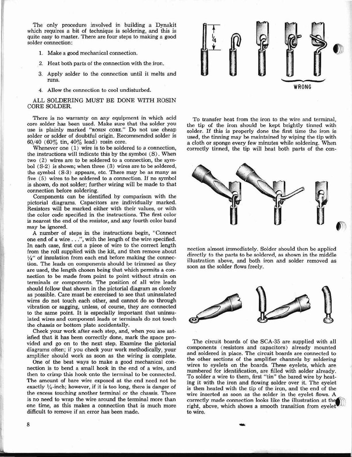
The
only
procedure involved
which requires a
easytomaster.
quite
solder connection:
1.
Make
a good mechanical connection.
2.
Heat
both
3. Apply solder to
runs.
4.
Allow
the
ALL
SOLDERING
CORE
SOLDER.
in
building a
bit
of technique is soldering,
There
are
four steps to making a good
parts
of the connection with
the
connection
connection to cool undisturbed.
MUST
BE
DONE
the
untilitmelts
WITH
Dynakit
and
iron.
ROSIN
this is
and
WRONG
Thereisno
core solder
use is
solder
60/40
the
two
bol (S-2) is shown; when
the
five
is shown, do
connection before soldering.
pictorial diagrams. Capacitors
Resistors will be
the
is
may
one
In
from
plainly
or
(60%
Whenever one
instructions will
(2)
symbol (S-3) appears, etc.
(5)
Components
color code specifiedinthe
nearest
be ignored.
A
numberofstepsinthe
endofa wire
each case, first
the
%" of insulation from
The
tion.
are
used,
nection to be
terminals
should follow
as
possible.
wires
do
vibrationorsagging, unless, of course,
to
the
same
lated
wires
the
chassisorbottom
Check
thatithas
isfied
vided
and
diagrams often; if
amplifier should workassoonasthe
One of
nection is
thentocrimp
The
amount
exactly
the
isnoneedtowrap
one time,asthis makes a connection
difficult
lit
excess touching
to
warranty
has
been used.
marked
solder of doubtful origin. Recommended solder
tin,
40%
(l)
wires
are
wires to be soldered to a connection.Ifno
not
solder;
can
marked
the
endofthe
...
roll
supplied
leads on components should be trimmedasthey
the
length chosen being
made
or
components.
that
showninthe
Care
must
not
touch
point.Itis especially
and
component
your
work
been
go ontothe
you
the
best
to
bend
this
of bare wire exposedatthe
-inch; however,ifit
remove ifanerror
on
any
equipmentinwhich acid
Make
sure
"ROSIN
lead)
wire is to be soldered to a connection,
indicate
to be soldered to a connection,
further
be identified
resistor,
", with
cut
a piece of wire to
with
each
from
be exercised to see
each
plate
after
correctly done,
next
check
ways to
a small hookinthe
hook
onto
another
the
wire
CORE."
rosin core.
thisbythe
three
(3)
wires
There
wiring will be
by
are
either
with
instructions.
and
instructions begin,
the
lengthofthe
the
kit,
and
end
before making
that
pointtopoint
The
position of all wire
pictorial
other,
and
important
leadsorterminalsdonot
accidentally.
each
step,
and,
step.
Examine
your
work methodically,
make
a good mechanical con-
the
terminal to be connected.
is too long,
terminalorthe chassis.
around
has
been made.
the
that
the
solder
you
Do
not
use cheap
symbol
are
maybeas
comparison with
individually marked.
their
any
the
then
which permits a con-
without
diagramasclosely
cannotdoso
they
when
mark
wiringiscomplete.
end
terminal more
thatismuch
(S).
When
the
sym-
to be soldered,
many
symbol
madetothat
values,orwith
The
first color
fourth color
wire specified.
correct
remove
that
are
that
you
the
the pictorial
of a wire,
end
need
thereisdanger
band
"Connect
length
about
the
connec-
strain
leads
uninsulated
through
connected
uninsu-
touch
are
space pro-
your
not
There
than
more
the
sat-
and
To
transfer
the
tip
solder.
is
used,
a cloth
correctly tinned,
as
nection
directly to
illustration
soonasthe
on
components (resistors
and
the
wires to eyelets on
numbered for identification,
To
be
ingitwith
of
is
wire
correctly
right, above, which shows a smooth
to wire.
If
the
or
The
circuit
soldered in place.
other
solder a wire to them, first
then
heated
insertedassoonasthe
heat
from the iron to the wire
of
the
iron should be
this is properly done
tinning
sponge every few
almost
sections of
made
maybemaintainedbywiping
the
immediately.
the
parts
to be soldered,asshowninthe
above,
solder flows freely.
the
and
boards of
iron
and
with
the
connection looks like the illustrationatth
minutes
tip
will
heat
Solder
both
iron
the
SCA-35
and
cap;:lcitors)
The
circuit boards
the
amplifier channels
the
boards.
are
"tin"
flowing
tip of
the
solderinthe
and
terminal,
kept
brightly
the
first time
while soldering.
both
should
and
solder removed
are
These
filled with solder already.
the
bared wirebyheat-
solder
over it.
iron,
and
transition
tinned
the
iron
the
tip with
When
partsofthe
thenbeapplied
middle
supplied with all
already
are
eyelets, which
connected
by
The
the
endofthe
eyelet
from
mounted
soldering
eyelet
flows. A
eyelet
with
con-
are
is
as
to
8
-

fRONT
1(/)Place
are
facing you,
at
the
the
pictorial
be
sure
pilot
light
with a
lockwasher
panel
smallest
(v'>
Install
2
the
pilot
%/f lockwasher on
shaft
nut.
Before tightening
necting lugs of
)n
the
("""'"
Install
3
Place
and
secureitfrom
fore tightening
the
connecting lugs shown on
and
see
(\A
InstaIl
4
using
lugs
as
(v,
Install
5
with
%" hardware, positioning
..,.as showninthe
6(
I"}
The
switches
power switch from
out
nearest
ing lugs
diagram.
threaded
Install
fierted
VJ
The
7(
three
They
cutouts--their
NOTE:
called
lorinthe
PANEL
the
front
bottom~
that
socketatthe
#4
which
size
the
light (see
through
diagram.
the
a %" lockwasheronthe
that
the
%"
hardware
showninthe
the
power switchisthe
with
areinthe
The
anddonot
the
from
shouldbemountedinthe
The
selector
MECHANICAL
panel
before
with
the
asinthe
diagram
you
are
proceeding correctly.
screw
inserted
and
nut
from
is toward
supplied
treble control
the
the
the
panel,
the
control
bass control (167205) in
the
the
nut,
the
bass control is positioned correctly.
balance control (167754)inthe
and
pictorial diagram.
volume control (177254)inthe
pictorial diagram.
only
two connecting lugs.
the
the
pilot
light socket so
position showninthe pictorial
slide switch
require lockwashers
power switch
the
front side of
remaining slide switches
orientationisnot
switch
instructions.
should
yousothat
rectangular
pictorial diagram.
before
and
extreme left
from
the
inside
you).
The
with
the
(marked
pictorial
shaft
and
the
nut,
are
outside with a %/f
observe
positioning
only
inside,inthe
with
the
notbeinstalled
ASSEMBLY
its
"wings"
switch
after
endofthe
the
outside,
(the
#4
screws
kit.
167504) next to
diagram).
before inserting
secureitwith a %"
see
positionedasshown
the
shaft,
insert
the
the
pictorial diagram
the
the
connecting lugs
one of
rectangular
that
mounting
two
#4
panel.
three rectangular
important.
cutouts
Refer
each
step
Install
panel
and
sideofthe
are
Place
that
the
next hole.
the
shaft,
nut.
orientation
next
connecting
next
the
Install
its
connect-
holes
and
nuts.
screws in-
are
identical.
until
later.
the
the
the
con-
Be-
hole
hole
slide
the
cut-
are
when
to
to
of
4(~The
5(
~Connect
6(vrConnect one
a
7( ...,--connect one
a
8(..-)
9(
~bserve,
numbering of
the
on
red
other
trollug
trol lug
lug
lug
lug
lug
Twist
nect
#
control
which
wired to
by
modules exactly to
insulating sleeving on the leads
modules should be connected whileintheir
position.
The
the
bass control so
visible; this
the
the
flat
connected
the
like
pictorial diagram.
wiretotreble control lug
end
to bass control lug
one
#2
#2.
# 5. Connect
#6(8).
#2.
Connect
#1
(8).
together a
one
endofthe
4.
Connect
lug
on
the
PEC-555002 tone control modules
the
carefully Gutting
Lead
#1
#2
#3
#4
#5
#6
#7
PEC
modules
picture.
front panel. After
first module,
againstitin
to
controls.
the
diagram.
the
lugsonthe
Connect
end
(8).
end
end
the
#5
(8).
the
bass, treble,
2/f
1
of a 2
12"
green wire to treble con-
Connect
of a2"red
the
of a2"green wire to bass control
the
5"
same
pictorial diagram, the
the
other
other
black
and
black wire to
endofthe
and
the
leads of
the
following lengths; slip black
2"
Ph/f
1%"
1114"
2"
DO
NOT
CUT
should
Place
the
that
module
the
the
the
terminalsonthe
The
complete assembly should look
be connectedasshown
first module flat
the
numbers
connects to
all
connections
second module will be placed
same position,
controlsisshown
one
#5
#5.
other
wire to bass control
end
endtobalance control
volume controls. Begin
as
lo/i" of sleeving
1%" of sleeving
1"
1"
1"
1%"of sleeving
3%"
end
(8).
end
to balance control
a
5/f
red
balance
red
wire to balance
one
of
specified.
of sleeving
of sleeving
of sleeving
of sleeving
markedonit
terminals
and
rear
of a
Connect
to bass con-
wire. Con-
control lug
manner
the
The
against
nearest
are
made
its
sections of
2Vz"
the
in
are
circuit
PEC
final
in
the
are
to
to
leads
These
gether some wires.
tightlyorthe
twistissufficiently
will remain together;
1(
2(
3(""'f
A
~.
instructions frequently specify
0"
Twist
of one wire to
the
same
lug
#2
.)ater
v1
Twist
they
ing
ends
pd
of
Cut
each
Connect
power
to
power switch
fRONT
wire
together two9"green wires.
endofthe
(8).
be connected to
together a
are
evenatone end.
to power
the
other
leadofthe
one
switch lug
PANEL
This
twisting should
may
cut
tightaslongasthe
thereisno
pilot
light
The
opposite
12%"
switch
wiretopower switch lug
leadofthe
#1
lug
WIRING
through
need
socket lug # 1
other
wire to
ends
the
main
and
a
Connect
lug #1.Connect
.02
mid
.02
(8-2).
#2
Connect
(8-2).
that
you
twist to-
not
be done too
the
insulation.
wires
are
for excessive twisting.
Connect
(8).
pilot
light socket
of these wires will
chassis assembly.
15/f
black wire so
oneofthe
disc
capacitor
mfd
disc capacitor
the
neat
one
Connect
match-
the
#2.
to
other
The
and
end
that
same
1;2/f.
lead
10(
11("")
12(
13(
14(~Connect
15(
16(...-r
17
to
..,
Connect
Connect
"'1'
Connect
-?l
Connect
~onnect
Connect
(V)
The
remaining PEC-555002 will nowbeconnected.
First, carefully
lengths
lating
Lead
PEC
lead
PEC
lead
PEC
lead
PEC
lead#4to bass control lug
PEC
lead
PEC
lead
PEC
lead
cut
and
slip
sleeving on
#1
#2
#3
#4
#5
#6
#7
#1totreble control lug
#2
to treble control lug
#3
to bass control lug
#5
to bass control lug
#6
to balance control lug
#7
to volume control lug
its
leads exactly to
the
specified lengths of black insu-
the
leads which require it.
2"
7/s"
10/0" !
%"
%"
lI
IVz
DO
NOT
CUT
1%"of sleeving
No
3%"
the
sleeving required
of sleeving
-
#4
(8).
#6
(8).
#4
(8).
#5
(8-3).
#6
(8).
#4.
#5
(8).
following
9

18
(~
Connect
19 (
'1'
Connect
20(,)Connect
21
(~
Connect
_
22(..{
23(,,1)
24(~
25(
26(
27 (
28
29(~Connect one
Connect
Connect
Connect
v('Connect
lug
~Connect
filter switch lug
switch lug # 5.
~
Connect one
lug
trollug
(0'
Connect one
switch lug
ance
lug
control lug
30(~nnect
lug
trol lug
31 (~Connect
switch lug
stereo-mono switch lug
which this
(v)Connect one
32
#2
switch lug
switchesasshowninthe
33
(~wist
nect
#3.
ance
34(
~onnect
control lug
ume
35(vr-Connect
control
volume control lug
36(
~nnect
orange) resistor to loudness switch lug
the
37(~
38(
39M
Connect
gray-orange) resistor
9'>nnect
..,..
Connect one
loudness switch
leadtovolume control lug #
Cut
a %" piece of insulating sleevingonthis lead
connectitto loudness switch lug
nect
PEC
lead
PEC
lead
PEC
PEC
lead#4to bass control lug
PEC
lead
PEC
PEC
lead#7to volume control lug
one
lead
#1.
Connect
one
leadofthe
lead
#3
(S).
Connect
#4.
leadofanother
#6
control lug
end
#4
(S-2).
#3
one
end
#1
(S-2).
#6
(S).
one
endofan
#5
lead
end
(S-2).
one
Connect
control lug
control
other
one
the
Connect
#5,
togethera9"
endofthe
the
one
end
#3
lug#1.
one
end
lug
#4
one lead of
lead to volume control lug
one
leadofthe
other
lead
lead
leadofthe
other
# 1 to treble control lug # 1
#2
to treble control
lead
# 3 to bass control lug # 1
#5tobass control
lead
#6
to balance control lug
of a 10ofcapacitor
other
lead to filter switch
other
#4.
Connect
of a 3.3nfcapacitor
the
(S).
Connect
#3.
of a
6%"
Connect
(S).
of a
6%"
Connect
(S-2).
is positionedinthe
of a9"red
the
positioning this lead above
green
black wire to balance control-lug
same
#2
(S).
of a
(S-4).
Connect
of a 3
(S-4).
#4.
an
to volume control
of a 22oftubular
lug
#1
other
lead
to volume control lug
the
other
lead to balance con-
3.3ofcapacitor
the
green wire to filter switch
the
other
red
wiretofilter switch
the
other
1
8
12'"
green wire to filter
Conn'ect
#4.
Note
wire to filter switch lug
other
end
pictorial diagratp..
anda9"
endofthe
3Vz"
black wiretobalance
the
1
/2"
black wire to balance
Connect
18,000
other
18,000
to
loudness switch lug
(S-2).
8.
22ofcapacitor
lug
lug
to filter switch
10nfcapacitor
other
lead to filter
to filter switch
other
end
end
to volume con-
the
other
the
diagram.
to stereo-mono
black wire. Con-
green wiretobal-
other
the
other
ohm
(brown-gray-
#1.
#4
ohm
lug
capacitor
Connect the
- .
#4
(S-2).
(S).
#3
(S).
(S).
#2
(S-3).
#3
(.8).
#3.
#2
(S).
lug
#2.
to
to filter
lead to bal-
to volume
end
to
manner
endtovol-
(S-2).
# 1
to
#7.
the
end
Connect
(brown-
#4.
(S-2).
other
I".
Place
and
Con-
in
to
to
40(
~onnect
lug
control lug
41
(~Connect
switch lug
...;rme control lug
42(
1'5
Connect
orange) resistor to stereo-mono switch lug
nect
43 (0'Connect one lead of the
black-orange) resistor to stereo-mono switch
#3.Connect
lug
44
(....f
Connect
switch lug
45(v1"Connect
switch lug
This
completes
(.I)
Place
Four
with
in
diagram;
Use a
washer
When
outs,
.J)Ot touch
(~
There
with
each of
shown
from
over
diagram
on
Set
time.
REAR
nection
check to see
panel which is still
switch.
present
1
2
"-
one
end
of a2"red
#2
(S).
Connect
#8
(S-2).
one
end
#5
(S).
#7
one
lead of a 10,000
other
lead to stereo-mono switch lug
#5
the
that
aside
the
identical
four
each
#4
mounting
center
are
four screw terminals.
on
the
the
the
(S-2).
one
one
PANEL
of
-ihese
and
the
-
end
#1
(S-2).
end
#3
(S-2).
the
front panel sub-assembly.
front
panel
this has been done
empty
the
front
MECHANICAL
rear
panelsothat
input
input
sockets on it.
the
cutouts
strips
screw,
nut\
the
the
stripssothat
the
chassis.
two identical
two
the
pictorial qiagram; these
outside.
screwatthe
instead
of a lockwasher.
7 each hole.
3(V"fThere
(~ount
4
should
5(vJ
6(
~he
fits a hole
are
two AC convenience outlets.
in
of these
in
the
the
inside. Use
holder
sideofthe
against
to
fasten
B. .
lug
I~>the
two
the
position of
pressing
panel
each of
pictorial diagram.
the
fuse holder.
be fitted
beforeitis insertedinits
panel. While pressing
the
panel,
it
,in
.,.-
rubber
hum
controls
the
in
them
firmly
from
the
#4
place.
the
inside.
wire to loudness switch
the
other
end
to volume
-
1
of a 2
12"
green wire to loudnes
Connect
(S-2).
other
of a5"green wire to stereo-mono
of a
shoulld have been soldered;
will
panel
socket strips
are
inserted
for
each
two
cutouts
Be
suretomount
place
the
hardware.
against
use
Note
grommet for
are
locating lug on each control which
chassis.
into
the
other
endtovo
ohm
(brown-black-
#4
other
10,000
lead
to stereo-mono switch
4"
red wire to stereo-mono
The
later
be filled by
sub-assembly for the
its
Mount
as
shown
mounted
from
mounting hole.
stripsinthe
the
output
cutouts
The
the
terminal strips,
Mount
providedatthe
indicatedonthe
The
rubber
the
shoulder of
special
position of connecting
"snap-in"
Snap
the
mounting
ohm
Every
hole in
the
ASSEMBLY
"wings" face you.
are
supplied,
one of these
in
the
from
the
the
outside, a lock-
two large cut-
metal
portions do
one
of these
strips
the
ground lug
Use
#4
Mount
provided,asshown
outlets
the
mount
washer provided
hole, from
the
fuse holder
%"
circular
line cord in
types. Observe
theminplace
holes on the
#1.
Con-
(S-2).
(brown-
lug
con-
the
front
selector
each
pictorial
inside.
NOTE:
each
in
locations
mount
pictorial
hardware
one
from
the
fuse
the
out-
nut
its
by
10

REAR
1(
~There
\,
2(~Connect
3
(/
4(iConnect
}he
5(
tI)
6(
0'Connect
L?"Note
7(
~(.4'Connect
U"
are
a total of sixteen
panel; the
number, shown
one
end
of a
lugs between sockets
endtothe
and
#4
(8).
another
between
the
Connect
between
lugs between
between
#5
short lugs between
another
#9
one
#13
short lugs between # 15
Connect
lugs between
endtothe
lugs between # 15
remains free for
input
#2,
sockets
#
1,
#2,
and
to
to
socket # 10,
one
one
the
circuit module to
#3
and
#1
lead
lead
2 to socket
lead 4 to socket
the
the
following lugs: lead 1 to socket
the
short lugs between
to socket # 12
9(
0'
length of flat, 4-conductor cable
plied
with
one 10" long
rate
the
four wiresateach
about
11;2",
ends. Connect
lugs of
The
)pter.
10(!""')
11
(i
i.2(~
Connect
the
The
later.
(0
Connect one
(8-2).
thatitcan
gether
Connectanend
the
Brown to socket # 5
Redtosocket
Orangetosocket
Yellowtosocket
opposite
one
long lugs of
Brown to socket # 13
Red
Orange to socket # 15
Yellowtosocket
opposite
Bend
with
PANEL
center
(long) lug of each socket
in
1112"
pair
of short lugs between sockets
1
and
#6
1112"
and
# 10,
#11
more
and
end
of a
#7
and
WIRING
the
pictorial diagram. Connect
black wiretothe
#1
and
1
12"
black wire to
(8).
#7
black wire to
and
and
#12
11;2"
black wire to
#14
(8);
11;2"
#8
short lugs between
end
of a
2%"
and
# 16
the
present
method
0 to
other
the
and
input
be identified
other
of connecting
#4,
and
and
#2.
the
short lugs between # 1
#2,
#4
PEC-555003
lead
3 to socket # 11
(8).
kit.
Cut
and
the
other
strip
one
endofthe
sockets in
ends
are
endofthe
the
input
to socket
ends
are
end
of a 101;2"
the
free
endofthis
wires.
of a
101;2"
the
to
Connect
lead 3tosocket
(8).
the
If.t'' of insulation from all 16
#6
not
12" piece of flat cable to
#14
nottobe connected
later
input
sockets on
#2.
Connect
Connect
and
the
black wire to
(8-2).
black wire to
long lugs of sockets # 1,
the
#9
12"
(8).
# 7
#8
socketsasfollows:
#16
red
the
#8.
other
endtothe
(8).
and
the
and#16.
Connect
#15
and
(8-3).
time.
The
the
short lugs between
lead 1 to socket
input
circuit
and
# 10,
(8),
has
cable
into
long.
Carefully
end
of each piece for
!O"
piece to
the
following
(8).
(8).
(8).
to be connected
(8).
(8).
(8).
(8).
red
wiretolug''''#10
wire to
whenitis twisted to-
wire to
the
has
pair
of short
the
the
short lugs
other
end
the
short lugs
the
short lugs
other
end
the
the
other
#16.
the
other
PEC-555003
#3
module
#9,
lead 0
lead
and
lead 4
been 'sup-
two pieces,
the
manner:
markitso
lug
#9
(8-2).
other
short
short
short
(8),
2 to
sepa-
long
until
until
rear
#3
to
to
end
and
13 ( vt'
Connect
short lugs between sockets
Twist
a
this
nectedtolugs
14(~onnect
(8-2).
15(~
16(~Connect one
17
Connect
.
Y:;-2).
of short lugs between sockets # 1
Twist
nectedtolugs
(..-1'
The
strips
the
bare wire
of
endtooutput
18
(wi.!
Connect one
lug
minal
19(,;(Connect
in
#4
a piece of bare wire across
which correspond to
amplifier will furnish a signaltoa derived
channel
speaker
connection
20(/(
21
22(
23 (
24
25
26( )
panel sub-assembly.
soldered connections.
present.
Connect one
AC
AC
(0'Connect one
AC
of
.....,
Connect
the
lug
~onnect
the
(6Twist
end
control
to lug
(v(Twist
end
control
to lug
Insert
"GRND"
of
for
amplifier.
This
Bend
this
lugsonthe
are
pictorial
the
upper
on
the
strip
(8).
Feed
output
(8).
outlet
outlet
outletB.Connect
the
fuse holder
left
#2
right
together two 11" green wires. Connect one
of one green wire to lug
(8).
#3ofthe
together two 11" green wires.
of one green wiretolug # 1 of
(8).
#3ofthe
a sheet-metal screw
above
the
chassis.
an
external
completes
one
end
of a
12"
wire together with
#9
and
# 10.
one
endofan
the
free
one
endofan
endofan
wire
together
#1
rearofthe
numbered
diagram~onnect
to
the
ground lug on
output
lug
end
mounting
(8-2).
one
end
of a
the
other
lug
#3
On
the
speakerifthis
connected
are
coveredinanother
end
A. Connect
B.
endofa
one
end
hum
control
of
the
right
one
end
hum
control
Connect
left
Connect
the
This
ground wire when installing
the
first portion of work on
Note
8et
8%"
endofthis
8112"
11
and
#2.
from # 1 to # 8,
terrpinal strip.
ff8. '
of a
4"
screw of
2"
bare wire to
endofthe
(8)
and
outside of
#4
wire is removed
in
its place.
of a
Ph"
the
1"
the
(8).
of a2"black wire to lug
(8).
hum
of a
10"
(8-2).
the
hum
the
right
hum
input
will furnish a connection
that
aside
black
wire to
#9
and
# 10
the
two
red
green wiretolug
wiretomark
green wiretolug
%" black wire to
and
with
the
green wires con-
output
black wire to
connectitto
the
the
and
#8
black wire to lug
other
black wire to lug
other
Connect
control.
black wire to lug
same
control
same
control
in
sockets, from
there
this
screw
as
one
end
the
mounting
Connect
the
upper
output
wire
through
back
panel
two screw
output
Instructions
section.)
end
to lug
endtoterminal
the
other
#1ofthe
endofthe
(8).
Connect
the
endofthe
(8).
the
hole
are
several non-
assembly for
the
pair
(8-3).
wires con-
the
# 2
(8-3).
terminal
shown
of a l,,%"
screw
the
other
the
ground
output
lug
the
output
connect
terminals
lugs.
center
and
a loud-
for
#2
#1
#2
#2
end
#2
left hum
other
right
other
marked
the
outside
point
the
of
#2
it.
#1
pair
on
ter-
#7
hole
lug
(The
this
of
of
of
B
of
to
of
wire
one
hum
wire
'.
the
rear
the
1-

MAIN
1
(~ss
Z-565 through
front of
the
are
leads which pass
five
Before
four
with
cable clamp
screwsasindicatedonthe
the
and
lug,
nut
2(V)
Pass
through
of
the
in
the
with
on
diagram.
NOTE:
outside
assembly
3(....-)Use
transformeratthe
tion
black
closest to
.
~ds
4(V)
Before
stall
V-8onthe
components
sockets
tion. Refer to
tion.
bottom
washer
5
(~Mount
bottomofthe
gram,
board.
~ween
6tv"'5
Mount
position shown
hardware, from
v5"
Install
7(
the
the
secure
8
(1,1'
The
1(0)
the
chassis; note
on
the
pictorial diagram.
in
this
provided, from
diagram
located.
%-turn
firmly
12
CHASSIS
the
leads of one of
the
correct
in
two groups:
other
leads which
attaching
setsof#8
the
kit),
MECHANICAL
the
two holes provided
chassis (see
location).
through
the
hardware
mount
under
two of
the
the
The
leads of
the
orange, black,
the
pass
transformertothe
(the
a 5-lug terminal
the
pictorial diagram.
lockwasher between
between
and
under
the
the
nut
under
all
the
the
cable clamp.
leads of
the
two holes providedatthe
chassis, observing
pictorial diagram.
#8
hardware,
one
of
the
mounting
Instructions
the
instructions.
#8
hardwaretomount
United
for
States.
indicatedonthe
and
yellow leads should pass through
the
rearofthe
through
mounting
the
on
four
each
the
sockets
top
of
are
mounted).
boarddonot
the
the
the
Use
#4
hardware;
of
the
circuit
and
nut
from
the
two
PC-lO
the
and
terminal
other
nuts.
the
power transformer PA-774
the
Mount
and
install
screws
PB-028. a 120/240
willbefoundatthe
rear
of the chassis,inthe
pictorial diagram.
chassis,
other
hole. .
two
PC-lO
supplied
boards
pictorial for
insert
board
the
top.
circuit
chassis,asshownonthe
using
four
setsof#4
Note
their
orientation,
the
boards.
the
PC-11 preamplifier
on
the
the
bottomofthe
the
two filter
bottom of
rear
corner, using two sets of # 4
each
wafer.
capacitor
the
chassisinthe
four-section filter
mountsinthe wafer
the
position of the symbols
underside
.of
the
The
position.
Then,
with
against
Insert
the
top of
to
'see
that
twist
pliers, while holding
the
wafer from above.
hardwaretomount
pictorial diagram, using
capacitor
nearesttothe
capacitor,asshownonthe
capacitor
the
mounting
the
markings
each
ASSEMBLY
output
transformers
nearest
pictorial
rear
through
diagram
the
transformer
and
chassis hole;
the
front hole.
yellow
chassis with
largest
transformer
size
strip
mounting
supplied
and
Insert
nut
and
cable clamp,
strip
mounting
Do
not
tighten
rear
corner
lead
orientation
the
shown
transformer
a 5-lug terminal
as
the
volt
other
shown
transformer
endofthe
Z-565
The
in
for
regular
output
orange,
the
and
the
remaining
circuit
for V-5, V-6, V
(the
side on which
Note
that
faceinthe
the
the
and
boards in-
-7
the
pairs
same
direc-
correct orienta-
screws from
install
the
boards from
pictorial dia-
and
leave
air
space
circuit
boardinthe
chassis.
mounting wafers from
cutouts
provided
hardware
(marked
60/40/20/
center
stamped
must
be
mounted
lugsinthe slots
the
chassis; check
are
correctly
of
the
mounting
the
capacitor
the
for
and
the
the
strip
the
use
posi-
holE!
~d
the
the
lock-
the
each
#4
at
to
of
the
lugs
~The
9(
same procedureasin
to install
50/50)
symbols
are
differently positioned
capacitor.
inserting
The
leads of
than
longer
with
former
proper
is necessary to
lead
lead
connection point, following
diagram. After
%"ofthe
the
end
insulation
by
heatingitand
vents fraying
cal bond before soldering.
1(
..('
Connect
former to
section filter capacitor.
position.
2 (
\t
Connect
former to lug
section filter capacitor.
"'position.
3
(V'J
Twist
white leads from
front
of
to
pin
leadtopin
4 (
~Twist
output
chassis. Connect
(S).
of
5
(V"')
Connect
Twist
white leads from
to
the
white
and-white lead to
6( vf
Twist
put
transformer nearest to
Connect
nect
the
7
(vr--Twist
transformer
leads to
8(
~Connect
.
~
#5
9 ( J.1""Connect
Jp-mounting
10(0"Twist
from
the
the
cable clamp,
lug # 1 of terminal
and-white
NOTE:
into
the
thereby
other
11
(prTwist
from
the
the
cable clamp,
the
the
two-section filter
in
the
remaining wafer.
stampedinthe
undersideofthe
than
Mount
and
MAIN
the
positioning. In
the
two-section filter
twisting
its
CHASSIS
transformers
make
mounting
WIRING
may
the
each
is to be connected, first
the
path
cutting
the
from
proper
the
endofthe
length of
applying
strands
the
lug
and
red
#4
ensures
lead from
(square
a more secure mechani-
the
See
the
red
lead
from
the
#4
(square
See
together
the
#7
together
transformer
together
rear of
leadtopin#7of V-5
together
the
blue-and-white
the
output
chassis. Connect
of V-7
#9
(S).
of V-7
the
blue
Connect
(S).
nearest
the
blue lead to
the
green
the
blue-and-white
the
output
the
chassis.
pin
#9
the
blue
transformer
the
and
leadtopin
Connect
(S).
of V-5
and
the
the
blue
leadtopin
green
together
leadtopin
the
two red leads from
#9
PA-774. Connect
lug
#4
of terminal
the-
other
red power transformer
of terminal
the
red-and-yellow power transformer lead
strip
lug.:Aofthe
together
the
brown
strip
TS-l.
four-section filter capacitor.
and
power transformer.
and
connect
strip
TS-2.
leadtolug
These
transformer leads
eyelet
providing
wires
tobeconnected.
together
the
power transformer.
that
and
#2
holds
more
green
connect
of TS-2.
the
space
and
Pass
-
preceding
capacitor
stepisused
Note
(marked
that·
the
capacitor
for
the
other
filte
capacitor
lugs.
often be somewhat
connections required
case where a trans-
run
the
lead to
showninthe
lead,
the
pictorial
lead,
and
strip
"tin"
solder to it; this pre-
rear
output
symbol) of
the
trans-
four-
pictorial for wire
front
output
symbol) of
the
trans-
four-
pictorial for wire
and
green-and-
nearesttothe
blue-and-white lead
the
green-and-white
green leads from
to
the
front of
pin
#7
#9
of
and
green-and-
transformer
nearest
the
Connect
the
the
of
N-
V-B.
blue-and-
the
green-
(S).
green
leadsofthe
rear of
#7
of V-6
the
chassis.
(S).
out-
Con-
of V-6.
the
power
either
one of
the
red
TS-l.
lead
brown-and-white leads
Pass
the
leads
under
the
brown lead to
Connect
the
brown-
shouldbeinserted
terminal to
on
the
lug
the
for
strip,
the
green-and-white leads
these leads
the
green
lead
unde
to lug
b
its
to
to
\
I

#4
of
terminal
white
lead
NOTE:
into
thereby
other
12
(nhe
with
types
although
they
nect
one
#2
the
#4
IMPORTANT:
shown
hold
the
sive
13(""""Connect
diode to
other
14( """-Connect
terminal
excessive
end
section filter capacitor.
15
V)
Connect
lug
capacitor
~6(
v1"'Connect
17
(Vf
watt
section filter
to
Connect
red)1watt
the
other
two-section filter capacitor.
(square
These
the
eyelet
providing
wirestobe connected.
silicon rectifier diodes
the
shown
are
the
of
the
of
terminal
other
of
terminal
in
pliersonthe
solder
heattothe
leadtolug#5of
to
lug
#3
(semi-circle
symbol)
resistor
lug
#1
four-section filter
leadtolug
~~onnect
-====
19(
20(
21
22(
(semi-circle
tor.
Connect
PC-lO
circuit
~Connect
Ih
watt
resistortolug
the
two-section filter
other
leadtolug
capacitor.
\1"'Connect
(triangle
(S-2).
PC-l1
(0'Connect
mounting
Connect
the
"'fConnect
lug B of
nect
section filter
Connect
circuit
same
the
strip
TS-2.
to lug#5of TS-2.
transfonner
that
holds
more
kit
maybeanyofthe
in
the
different
electrically
cathode
rectifier diodes
lead
the
connection to avoid
the
cathode
lug
#2ofterminal
one
endofa7"red
strip
heatingofthe
#3
one
leadofthe
(S-2).
one
lead
to lug
capacitor
(triangle
one
leadofthe
resistortolug
one
symbol)ofthe
the
one
lead
one
symbol)ofthe
board
one
leadofthe
lug
the
other
capacitor.
one
end
the
four-section filter
other
capacitor.
in
equivalent. Con-
(or
plus)
strip
TS-l.
of
the
diode
strip
TS-1
Arrange
pictorial diagram.
lead
between
diode.
(or
terminal
TS-1
(S-3).
(semi-circle
symbol)ofthe
Connect
of
the
of a 2200
#4
(square
(S-4).
symbol)ofthe
capacitor
#2
(semi-circle
end
of a 61!z" red wire
other
endtoeyelet
board
end
B of
(S).
of a 22,000
#2
capacitor
# 1
(triangle
of a 61!z"
the
~ther
(S).
the
four-section filter capacitor.
leadtolug
of a
2"
endtomounting
Connect
leads
the
space
supplied
illustration;
appearance,
lead
to
Connect
to
(S-2).
the
diode
plus)
strip
wire to
Use
diodes.
symbol)
50 ohm, 5
the
other
same
ohm
Connect
other
#1
two-section filter capaci-
ohm
(semi-circle
two-section filter
endtoeyelet
95 ohm, 5
black wiretomOlmting
capacitor
the
green-and-
shouldbeinserted
tenninaltothe
on
the
lug for
three
~
UJ
Cl
O~Cl
.~~~.
U
of
lug
~
"
lug
leads
exactly
When
the
application
leadofthe
TS-l.
strip
caution
Connect
four-section filter
capacitor.
symbol)ofthe
2200
(triangle
(S-2).
(S-3).
symbol)ofthe
red
#2
lug D of
soldering,
diode
body
of exces-
Connect
TS-l
(S-2).
lug
# 2 of
to
the
of
the
watt
resistor to
leadtolug
(red-red-red)
the
othef..lead
same
capacitor.
ohm
(red-red-
symbol)
Connect
symbol)
to
lug
#5ofthe
(red-red-orange)
symbol)
Connect
wire
to
lug
capacitor
#12
watt
resistor
(no
symbol)
(S-2).
the
strip,
the
UJ
<t
as
and
second
the
the
avoid
other
four-
#4
four-
of
the
of
the
#2
rear
of
the
same
#1
on
the
to
of
ton-
two-
23( 0
24(
25 (
26(
27(
28(,0Connect
29
30
31
Connect
lug
D of
nect
the
cuit
board
v(Connect
on
the
wireisalready
insert
eyelet
V"'Connect
lug
C of
the
other
cuit
board
W"'Connect
lug
C of
nect
the
eircuit
~onnect
V-7
(8).
V-8
(8-2).
(U
Co~p.ect
V-6
(S-2).
(VConnect
(8-2).
of
the
(~Connect
V-7 of
JP.
eyelet
32(~Connect
of V-8 of
endtoeyelet
33(
1
~Connect
V-5 of
to
eyelet
34(
~onnect
V-6 of
to
eyelet
35(
'1""
Connect
V-8 of
to
eyelet
36( ....,..-connect
V-6 of
to
eyelet
37(
1>'Connect
of front
#10
38(
~onnect
of rear
#10
39(A'"
40
Twist
3"
#3
of
(8).
#5ofV-5.
wiretopin
(V!.wist
2%"
#5ofV-5
wiretopin
of
endofthe
long.
on
the
the
one
end
of a 61!z"
the
two-section filter
other
endtoeyelet
(S).
one
end
of a
rear
PC-lO
the
second
#5
on
one
end
the
endtoeyelet
(S).
one
end
the
four-section filter
other
board
one
Connect
one
Connect
.
one
Co~.he
one
end
Connect
four-section filter capacitor.
one
end
the
front
#9
one
the
one
endofa 1Yt" green wiretopin
the
rear
#9
(S).
one
the
rear
#8
one
end
the
front
#11(S).
one
the
rear
#11(S).
one
PC-10
(S).
one
end
PC-lO
(S).
togetherapairofblack
Connect
the
rear
green wiretoeyelet
Connect
Connect
#4
togetherapairofblack
long.
Connect
(S-2).
#4
black
wiretopin
green
circuit
connected;
wire.
the
front
of a 4
four-section filter
of a 6
endtoeyelet
(8).
endofa
the
end
of a
the
end
of a 1
'of a
the
other
of a 11;4" green wire to
PC-lO
(S).
e~d
of a 1Yt" green wiretopin
front
PC-lO
#8
(S).
PC-lO
end
of a 1
PC-lO
(S).
of a 1
PC-lO
end
of a
PC-lO
end
of a 41!z" green wiretoeyelet
(S).
Connect
of a 4Yz" green wiretoeyelet
(S).
Connect
one
PC-10
the
other
the
of V-5.
one
Connect
of V-5
wiretopin
black
2Y2"
red
board
reheat
Connect
PC-lO
1
h"
black
#6
of
1
/2"
black wiretomounting
#6
11;4"
red
other
endtopin
21!z"
red
other
1
14"
red wiretopin
other
7."
red
.fmdtolug
(S).
Connect
-
(S).
(S).
Connect
J
14"
green wiretopin
(S).
Connect
Y2"
green wire to
(S-2).
Ph"
green wire to
(S-2).
the
the
endofthe
(S).
Connect
#4
endofthe
remaining
endofthe
the
(S-2).
# 5 of V-6,
#4
wiretomounting
capacitor
#4
circuit
capacitor.
the
capacitor
on
wire to
endtopin
encLt.9-Pin..#3 of-V-5,-
wiretopin
Connect
Connect
other
other
and
black wire to
on
and
same-end of
Connect
of
(S-2).
on
the
PC-ll
wire to
the
wire to
wire to
Connect
eyelet
(S-2).
green
black wire to
endofthe
green wires,
black wiretopin
Note
the
eyelet
other
board
mounting
rear
PC-lO
(S-2).
the
front
pin
#3
pin
#3
# 3 of V-5
#2
(no
symbbl)
pin
the
other
the
the
other
the
other
pin
the
other
pin
the
other
endtoeyelet
endtoeyelet
wires,
the
same-end
the
rear
the
the
other
and
the
end
(S).
Connect
PC-lO
# 3 of
of V-8.
#3
of V-6.
# 3 of
# 2 of
# 2 of
#2
# 9 of
# 9 of
eyelet
PC-10
green
green
V-G.
Con-
cir-
#5
one
and
cir-
Con-
end
other
end
end
end
end
each
pin
each
end
other
to
of
#2
of
#2
#2
13
--
--
--------------
-----

41
(vf
Twist
together a
2%"
long. Connect one
lug
#1
of terminal
to
pin
#5
green wire to lug
Jof
the
green wire to
42(~Twist
j to lug
43 (.,J)
j!!
V!wist
44 (
45(Vf'Twist
/!.f V-8
46
(1'>
WIRING
The
of
the
switch.
when
itisdone
are
connectedtothe
gram shows exactly which wires
the
eyelets.
wiresinplacebyheating
while
checkin~
been
insertedinthe
\
1(
Vl
2('£{
3(
4(0
together a
10%"
long. Connect one
eyelet
the
the
strip
Twist
3"
#3
of
2%"
wire to
of
endofthe
3"
the
endofthe
nect
Twist
12" long. Connect
let
green wire to
other
strip
wire
following wires
#9
green wire to
other
endofthe
T8-2. Connect
#2
of T8-2.
together a
long.
Connect
on
the
the
green wire to
(8).
Connect the
# 5 of V
# 5 of V-7(8-2).
#4oftenninal
PC-11 preamplifier circuit board to
To
-7.
pin
#4
together a
long. Connect one
pin
the
black wire to
together a
long. Connect one
green wiretolug
the remaining
(8-2).
together a
#15onPC-11
endofthe
T8-2.
to
lug # 5 of T8-2.
TO
make
Insert
the
LENGTH
5(a
6(
7(~
8('
9(
~
10(~
H(
12(
)
pair
of green
strip
of V-6
on
front
Connect the
of V-7.
#4
green wiretopin
black wire to
Connect
the
laterinthe
the
eyelet
1%"
2"
2%"
1%"
4"
H
5
1%"
4"
51,4"
1%"
2%"
2"
(8-2).
#2
of T8-2'. Connect
pin
pair
of green
PC-11
eyelet
THE
proper
(8).
eyelet
#10onPC-ll
black wire to lug # 1 of
the
pair
of black
one
end
PC-lO
eyelet
other
pair
of black
Connect
of V-7
strip
are
wiring to
circuit
(8-2).
pin
pair
of green
endofthe
T8-2. Connect the same
#5
endofthe
pair
of green
one
endofthe
(8).
Connect the
# 13onPC-11
black wire to lug
the
PC-11 CIRCUIT BOARD
all
to be connected from
assembly process,
board
wires from the top,
the
eyelets from below
numbers to be
eyelets.
and
black wires,
endofthe
T8-2;
connect
Connect one
#4
of V-6
and
endofthe
Connect
other
endofthe
and
of the black wire to
(8).
Connect
#4
end
of the black wire to
other
endofthe
and
end
of the black wiretopin
the
same
Connect the
# 5 of V-8,
# 4 of V
and
of T8-2.
pin
#5
green wiretopin
and
remaining
the
selector switch easier
now.
are
connectedtoeach
COLOR
red
red
red
red
red I
black
green
green
black
green
green
green
black wire to
the
end
the
(8-2).
bla<;k
wires,
black-wire to
the
same
(8).
green wires, each
the
on
the front PC-lO
green wires, each
endofthe
and
-8.
black wires, each
black wire to lug
Connect
of V-8
sure
(8-2).
black wires each
black wire to eye-
same
(8).
Connect
#4
of
endofthe
the
The
pictorial dia-
and
that
each
other
end
of the
other
end
each
end
of
Connect
tenninal
green wire
eyelet
same
end
pin
green wire
green
other
end
the
other
end
of
the
other
Con-
#4
endofthe
the
tenninal
green
the
top
selector
the
wires
of
solder
the
the
board,
they have
EYELET
#16
#17
#14
#19
#20
#5.
#2
#3
#1
#8
#11
#7'
FINAL
The
top of
With
the
a locating lug
diagram shows the
wafersasA
location has separate lugs
wafer, be
1
(n
Connect one lead of a 1.5 megohm (brown-greengreen) resistor to selector switch lug B-2. Connect
2
(Y5
Connect one lead of a 3.3nfcapacitortoselector
switch lug B-5
lug B-2.
3
(VConnec1
green-green) resistor to selector switch lug A-2.
"connect
(v'f Connect
4
switch lug A-5
5("-'r"Attach
chassis with four
each
the
6
(\IfCarefully install the selector switch
panel
the
selector switchismarked
shaft pointing toward you,
protrudes
tenninal
(front)
sure
you
solder each wire to
the
other
lead to lug B-5. .
one
lead of
the
other
one
lead
lug A-2.
the
front
sideinthe
two wires from
under
the
chassis.
as
showninthe
%" lockwasher
switch,
front
indicates
the panel.
front of
the
with a
7(
~Connect
circuit board to lug A-7onthe
B(
if
Connect
circuit
9(
lI"I
Connect
>-J;.
lOvP0sition
red
Position
wafer A (between the wafer
the
(8).
11
(~onnect
A-2
C0
12
13( lIIf
14(~Connect
15(
16
17
Connect
B-7
Connect
B-9
fi-6
"'1'
Position
green wire from
Position
wafer B (between wafers B
Connect
black wire to B-3
C,j)
Connect
B-2
(\l'.Connect
to lug
insert
panel
and
the
In
the
switch should engage
front panel.
%"
nut.
the
red
the
red
boardtolug A-9onthe
the
(8).
the
black wire from
wire from
the
twisted
main
chassis).
Connect
the
(8-3).
the
(8).
the green wire from
(8).
the
(8).
the
black wire from
the
twisted
the
green wire to lug B-4
the
(8-3).
the
red wire from
A-l.
ASSEMBLY
and
from
the
left front.
numbers,
andB(rear).
on
(8-2).
the'
lead to lug A-5.
ofa.3.3nfcapacitor to selector
(8-2).
panel
sheet
holes provided.
the
on
the
the
switchinthe
rotateitso
top of
the
this position
Fasten
wire from
wire from eyelet
red
wire 'from
eyelet
the
red
green wire from eyelet # 8 to lug
green wire from
green wire from
# 20
pair
Connect
black wire to lug A-3
wire from
'
eyelet
#3
pair
(8).
Wheneveraterminal
the
front
Connect
other
Connect
sub-assembly to the main
metal screws, using two
stereo-mono switch
pictorial diagram.
bushingatthe
that
switchistoward
the
the
switch securelyinplac
eyelet
eyelet
and
in
front of selector switch
and
the
eyelet#lover
and
in
front of selector switch
andA,but
the
with a red dot.
the
dotatthe
The
and
identifies
and
backofthe
both
lugs.
the
other
1.5 megohm (brown-
the
other
Note
that
on
frontofthe
hole providf'donthe
the
red
locating lugonthe
the
small hole
#16
on
selector switch
#17onthe
selector switch
eyelet
twist
red
eyelet
twist them together.
eyelet
stereo-mono switch •
# 19 to lug
#5
over to
them
the front flange of
wire to lug A-4
#14
eyelet
eyelet
(8).
# 7 to lug
#2
closetoB).
Connect
# 11 to
top,
pictori
th
lead to
lead to
all
but
pass
the
front
Place
dot
which
the
top
the pc-n
(8).
PC-11
(8).
the
together.
(8).
to lug
to
lug?
to
the
the
lu
on
a
of
in
14
-

18(y(Connect
19
(~Connect
a
,'.
to
pair
front
the green wire from
lug
B-lo
the
black wire of
from
the
PC-10
(8-2).
balance
control to eyelet
Thisisthe
. nected to this eyelet. Connect
pair
to eyelet
20(~Connect
twisted
on
the
. connected
.)his
pairtoeyelet
21(""'Feed
the
light socket through
of these wires to
...£onnect
"1'"
Place
22 (
the
panel faces you. Bring
close
to
do
not
four
conductor
wires from
chassis. All
.
23
~tom
(~~nnect
between
fasten in placeatthis
the
pair
rear
twisted
the
main
the
of
the
the
input
#7
(8).
black wire of
from
the
balance controltoeyelet
PC-10
to
(8-2).
this
eyelet. Connect
#7
(8).
pair
of green wires from
the
lug
#4
other
green wire to lug
chassis
upside
cable clamp. Connect one
the
proper
the
the
position (also upside
cables
input
and
socketsonthe
other
wires will be connectedonthe
chassis.
black wire from the
sockets # 15
lug A of the four-section filter
24
(Y1'"
Connect the black wire from
tt
output
terminal
25(
"'~onnect
y 774) leads to lug
the
the
NOTE:Ifu.inl<
this
26(A
Connect the longer black wire of
terminal
strip
one of
other
black power transformer
fuse holder
steP
with
the
strip
T8-l
the
#1ofAC
(8).
the
120/240
steps
specifiedonPage
mounting
(8).
black power transformer
volt
power
power switch to lug # 1 of
other
27
( \-("Cut
black wire of this
B
(8-2).
;;able
put
chassis to
the
black
Position these twisted wires
clamp.
the
black, orange
transformer Z-565
3/1
leadtooutput
leadtdlug
each.
#2
Twist
(8).
pair
and
nearest
these together
lug
Connect
Jug #1.
28 (
'ItI'f
Connect
lug # 1
/to
29
(./)
Twist
from
the
Connect the black
Connect
.
yellow
30("A'"Connect one
lug
eyelet
31
(itConnect
-hum
section filter
.
r1
~
~he
32(11Connect one of
control to lug
Connect
(8-4).
one
end
(8·2).
eyelet
#1
on
together
the
output
chassis.
Place
the
orange lead to lug
leadtolug
end
#5
(8-2).
Connect
# 1onthe
the
black wire from
controltolug
capacitor
rear
panel.
the
other
Position these wires
of a 7112/1
Connect
the
the
the
rear PC-lO
black, orange
transformer
these leads
leadtooutput
# 5.
of a
9"
the
front
PC-10
#2
(8·3).
the
green wires from
#1
of terminal
green wire to lug
the
stereo-mono switch
the
red-and-black twisted
#6
second wire con-
the
red
wire of
the
green-and-black
Thisisthe
of terminal
second wire
the
green wire of
strip
#5
down so
rear
that
panel sub-assembly
down),
time. Position
the
twisted three sets of
top side of
ground
and
# 16 to
capacitor
the
(8-2).
ground lugonthe
screwtolug
outletB(8-2).
lead
to lug A
transformer,
16.
AC
outletA.Connect
to lug
PB-028.
the
pair
#2ofAC
under
yellow leads from
to
the
rear of
and
#8.
Connect
the
green wire to
other
the
yellow
output
endofthis
(8).
and
yellow leads
nearesttothe
under
the
cable clamp.
strip
lug
#8
#6
(8).
Connect
red wiretooutput
other
end
of this wire to
(8).
lug
#2
of
(no
symbol)ofthe
Place
this
wire
the
strip
T8-2
#2
under
the
cable clamp.
on
the
this
#6
the
pilot
-'1'8-2.
of TS-2.
the
front
but
the
flat
the
lugs
mounting
#3
(PA-
Connect
on
replace
from
the
the
outlet
the
the
out-
the
connect
orange
lead
strip
wire
front
(8-3).
the
strip
the
right
four-
against
left
hum
(8-4).
of
T8-2
33
34(.,t
35
36
37(vj
of
38(~ist
to
39 (
40(
41(""') Connect
of
42~
43
44(JConnect
45(
46
THE
THE
V
Connect
control to lug
Connect
(8·5).
Now
Attach
one of the green wires from
#4
of terminal
the
other
green wire to lug
Position
tighten
the
these
wires
the
hardware
rear
panel sub-assembly to
holding
under
the
strip
the
the
T8-2
#5
cable clamp.
cable clamp.
chassis with four sheet-metal screws, using two on
each
side in
(~Pass
mounted
enough to tie a
Then,
for 2".
~
ends
(VConnect
to
lug
conductor to lug
tum
the
Twist
#9
and
between them. Connect
viously
cuit
board
shown on
of
the
connect
circuit
nected
wire to lug A-8 of
these wires from
the
holes provided.
the
line
cord
in the
rear
panel,
knot4"from
separate
Cut
the
two conductors of
'h" from one of them,
through
the
and
pushitthrough far
the
end.
and
of both.
the
#2
of AC
shorterofthe
outletA(8-2).
#1
of
two line
Connect
AC
outletA(8-2).
chassis over.
together the two red wires from
#10
and
the
black wire from
the
red
wire with
bent
endtoeyelet
(8).
(Note
the
pictorial diagram.)
black wire
the
board
to
around
black wiretoeyelet
(8-2).
this
eyelet. Connect
the
the
#18
on
the
correct wire position
Twist
the
remaining
Thisisthe
the
selector switch
rear
panel
#5
second wire con-
against
rubber
Tie
the
strip
cord
input
the
the
another
red
on
remaining
(8).
conductors
chassis.
together
sockets
short
with
PC-ll
#1
lugs betweeft them. Connect
the preyiously
circuit
position shown
another
tum
green wire
the
on
PC-ll
wire connected to
ing
green wire to lug B-8 of the selector switch
Position these wires from
main
chassis.
eI
Connect
)he
the
rear
panel to lug A-I of
D(Connect the orange wire from
/Iug
A-12
(8).
the
A-ll
(8).
Connect the brown wire from
lug A-lO
(v{
Connect
lug B-1
lug B-12
VConnect
B-ll
(J
Connect
lug B-lO
This
completes
AC CORD
COVER
(8).
AND
(8).
the
(8-2).
the
(8).
the
the
(8).
UNTIL
BO'ITOM
the
two
gr~en-·Wires
and
#2
and
the
bent
endtoeyelet
board
of
and
circuit
on
the
the
connect
board
(8).
pictorial
black
the
this eyelet. Connect
the
yellow wire from
the
red
wire from
yeUow wire from
orange wire from
red
wire from
brown wire from
the
wiring of the..-ubit. DO
THE
TUBES
HAVE
PLATE
ARE
from
black wire from the
the
(Note
the
correct wire
diagram.)
wi,re
on
the
black wire to
(8-2).
Thisisthe
the
rear
panel
against
input
socket # 16 on
selector switch
input
socket
input
socket
input
socket
input
socket # 8 to
input
socket
input
socket
input
socket # 5 to
NOT
BEEN
INSTALLED
SECURELYINPLACE.
right
hum
(8-5).
of
T8-2
the
main
grommet
the
knot
line cord
and
tin
the
longer
Now
sockets
short
lugs
the
pre-
PC-ll
cir-
tum
wire
and
the
PC-ll
red
Position
the
main
input
green wire
#6
on
the
Twist
remaining
eyelet
# 1
second
remain-
(8).
the
(8-2).
#15
to
#14
to lug
#13
to
#7
to
#6
to lug
PLUG
IN
AND
.
15

PLACES
Be
sure
Compare
showninthe
securely soldered, with enough space between connections
to
the
tube
ofanaccidental short-circuit.
Compare
to
that
showninthe
see
that
lead
length
to
the
chassis.
Examine
that
noneofthem
to touch
terminal
Check
panel, to be
Check
soldered to see
shorted
a
been
applied
twisted too tightly.
going to
V-B,
and
T8-2.
The
wires to
shown below.
and
A4,
the
front surface of
TO DOUBLE-CHECK
that
all
mounting
the
wiring of each of
pictorial diagram. All connections should be
socket connecting lugs so
the
wiring to each lug of
pictorial
all connections
has
not
caused
all
connections with
have solder blobs which
the
bottom
strips
each
sure
the
twisted wiresatthe
condition.
when soldering these wires
pins
#4
to lugs
Note
and
to lugs B3
plate
and
the
lug on
that
that
the
This
Pay
and
#1,
the
selector switch
particularly
each
screws
have
been soldered,
any
whenitis installed. Check
filter capacitorsinparticular.
eachofthe
all of them
insulation has
will occuriftoo
particular
#5
of tube sockets V-5, V-6, V-7
#2,
#4
and
B4.
wafer.
AFTER
and
the
that
diagram. Check carefully to
connection to short-circuit
particular
controls
have
ends
where
attentiontothe
and
#5
should
the
twisted
These
WIRING
nuts
are
tube socketstothat
there isnochance
the
filter capacitors
and
care,tobe sure
project
been soldered.
they
not
melted
much
and
they have been
of terminal
be positioned
pairstolugs A3
should
tight.
that
on
the
have been
to cause
heat
be close
excess
enough
the
front
has
leads
and
strip
as
to
The
bottom
time, by
which fits outside
cover
onto
are
fastened together by four
the
sides of
panel
is installed.
Install
sertingitfrom
gripping
to squeeze
spring over
place.
The
over
the
placedonthe
hold
the
attaching
the finish of
if necessary,
the
All
secure
required.
shaft
and
shaft
has a flatted portion,
should be tightened
rotated
is
knob
should
The
balance control
setsothat
7 o'clock
will correspond to 5 o'clock.
balance control
operation. However,
offset if desired so
average volume
The
bass control knob should be
clockwise
that
full clockwise isat6 o'clock.
will
thenbethe
plate
and
the cover
setting
the
the
control shafts,
panel
them
The
on
the
amplifier chassisonthe
the
main
the
chassis.
the
cover.
pilot
the
jewel
it
open,
the
panel
control
the
nuts
the
panel.
without
knobs of
to
two large knobs go
the
volume control shaft.
fully counter-clockwise,
pointto"Tape
the
full counter-clockwise
a clock face,
point
isat6 o'clock,
The
This
light
jewel
front of
spring
and
jewel
to
should
in
and
electrically "flat"
thenbeplaced
and
shaft
place.
Use
to avoid scratching
The
removing
the
8CA-35 use small
the
shafts. A small tip screwdriver is
against
and
and
to 12 o'clock for nominally
either
that
the
balanceinyour
and
are
attachedatthe
bottom plate,
chassis,
chassis, bottom
should be done before
the
with pliers
sliding
holditin
%"
bushings
cover
and
the
head".
volume control knobs should be
This
of these knobs
12 o'clock position represents
the
and
then
plate
sheet
metal screws throu
by
in-
panel,
the
nuts
to
care
in
can
afterward
the
front panel.
set
on
the
selector switch
The
selector switch
the
set
screwinthe
flat.
Then
when
the
index
point
corresponds to
then
full clockwise
makes
the
canbeinstalled
individual system.
setsothat
treble control knob
The
12 o'clock position
setting
for each.
lowering
mark
index on
full counter
same
the
and
cove
the
fron
be removed,
screws to
knob
the
knob
on
the
rotation
the
balanced
set
so
Tum
the
chassis upside down,
dislodge
torial
TANT:
first time,
chassis to avoid
tight
tubes
tubes; one of each is
closest
6BQ5;EL-84/7189 tubes,
PC-10 sockets.
holes of
machine screwinthe
it
16
any
The
tubes
diagram
When
fit of
and
to
The
four
the
witha#6
wire clippingsorbits of
and
the
fuse should now be mstalled.;
shows
inserting
the
socket should be
new
are
installedinPC-ll.
the
PC-ll
rubber
bottom plate.
nutonthe
the
strainonthe
sockets.
installed
board. V-5, V-6, V-7
Insert
the
feet should be
recessed
and
shakeitvigorously to
sol~er.
location of each tube.
the tubesintheir
supported
circuit
V-I
and
on each
and
pilot
To
mount
inside of
board
V-2
are
V-3
and
PC-10inthe
they
go
lampinits
installedinthe
each foot,
endofthe
the
bottom
in
the
pIC-
IMPOR-
sockets for
from below
because of
12AX7;ECC-83
V-4
and
the
socket.
inserta#6
foot,
and
plate.
the
the
the
are
7199
socket
V-8
are
remaining
corner
secure
.
Dynakit
transformer PB-028
or 240 volt, 50
For r
1( ) Connect
2( )
3( ) Connect
4(
) Connect
SPECIAL
120-240
INSTRUCTIONS FOR OPTIONAL
VOLT POWER TRANSFORMERS
BLACK
•
VIOLET
aWHITE
BLACK
aWHilE
I
.
VIOLET
120·Yol'
8CA-35 amplifiers
canbewired for
or
60 cycle,
20
Volt
Operation
the
black lead from
#1
of AC
to lug
Connect
transformer to lug #
fuse holder
the
the
the
outlet
black-and-white
violet lead to lug A on
violet-and-white lead to lug A on
(8-2).
,
1 of AC
BLACK
VIOLET
a
BLACK
aWHITE
t
VIOLET
240·yolt
supplied
AC
B.
with optional power
use
with
power sources,asfollows:
the
power transformer
lead
from
outletB(8-3).
the
fuse hoide
WHITE
either
the
.
120
power
the

for
240
Volt
Operation
1( ) Connect
minal
) Connect
minal
3( ) Connect
B
4( ) Connect
. holder
When using
blo fuse should be
recommended for
Although
assembly, sometimesanerror
ponent
may
difficulty
matic
approachisused.
the
inter-relationship between
circuit,
and
circuit will be helpful in achieving
suggestions for servicing which follow
the
strip
strip
violet-and-white
TS-l.
the
black-and-white
TS-1
(S-2).
the
black
lead
lead
lead
to
lug # 1 of
(S-2).
the
violet lead to lug A on
(8).
the
240 volt connection, a one
used
insteadofthe
the
120 volt connection.
IN
CASE
your
SCA-35 should function
OF TROUBLE
of wiringora defective com-
require trouble shooting.
can
be determined most efficiently if a syste-
This
is based
the
reference to
the
section which describes
The
different sections of
this
understanding.
are
to localize the circuit section which isatfault.
Naturally,
ing
as
a first
you
should
step
check
and
double check
in trouble shooting.Itis goodtohave
somebody else checkitthrough for you,ashe
error
which
you
be done with
the
step instructions.
check
on
the
accuracy
ires
and
componentsgoto
that
all
see
parts
or
bit
of solder will
solder connections
touch spots where
overlook consistently.
pictorial diagramsorwith
If
you
use both,
of wiring. Look
the
correct points,
are
they
run
from one
pointtoanother
This
you
will have a double
not
good
should not. Sometimes a
connection is desired. Sometimes a lead is left
and
hangs out, touching
should be examined
Another
tightly together
cause
source of trouble is
that
short
circuits -
with
they
this
or
another
in mind.
break
the
point. All connections
that
wires
through
wire itself
within the insulation if twisted too tightly.
made
One general test should be
shooting begins.
in
the
SCA-35orin
nections to
the
pickup cartridge is
Pilot
If
turning
see whether
tubes.Ifthe
then
the
Light
and/or
after
plugging
the
power switch on,
there
tubes glow while
the
fault
loudspeakers
is in
should be replaced socket.
connections
If
wiring to
two sets of
~hich
\
....
to TS-2 to see
some of
hite.
This
wiring should be traced to see whether
are
correct
the
tubes light,
the
unlighted
heater
is brown
These
and
should be traced from
if
This
is to determine whether
associated equipment. Sometimes, con-
areatfault,orit
not
connected properly in
TubesDoNot
the
SCA-35
the
is a
normal
the
pilot
orinthe
and
soldering makes good contact.
but
others
tubes
wires, a
set
brown-white,
the
wiring compares with
before serious trouble
light
into
an
pilot light does
glowinthe
the
pilot
light does
light itself -
wiring to
do not,
should be traced.
for
each
the
other
the
PA-774 transformer
diagram.
to lug # 1 of ter-
to lug
two
properly
#1
AC
the
ampere
ampere
of ter-
outlet
fuse
slo-
fuse
after
location of a
on
understanding
the
the
The
based on
checking
only
and
thatnowires
your
may
the
step-by-
to see if
but
trying
wir-
see
can
also to
where no
too long
are
twisted so
the
insulation
may
the
and
be broken
fault
maybethat
the
player.
AC
outlet
and
notgoon,
centerofthe
not
light,
and
the
bulb
the
pilot
light
the
then
the
heater
There
are
channel, one of
green
and
green-
the
pictorial
If
all
the
tubesinone
channel,
interchange
brown-white with green-white
whether one of these sets
example,ifthe
were formerly
the
with
interchange
not
wiring to the tubes,
something wrong with
(which should be
mentinthis
for locating
If
neither
to check is
rating
models).Ifthe
volt
to
determine
replace fuses.
higher rating be used.
Siown
The
ment.
should be
capacitor
each section of
of
these
case).
the
source of trouble.
tubes
the
fuse.Ifthis is blown,
should be used, 2
the
Under
fuses
fuse will blowifthere
If
an
ohmmeter
made
terminals.
the
measurements.
over 50,000 ohms
the
of
ohms. Any lesser resistance values indicate
an
failureora
nect
four-section
path
wires to each
All sections should
disconnected - if not,
all
If
one of
installed
ably
have been
if
the
four-section
failure of
diodes
are
Blown fuses
former
the
silicon diodes is defective,orifithas been
backwards,
permanently
the
silicon diodes. Therefore, if
found to beatfault, both should be replaced.
can
(though
thisisa
channel
the
light,
but
noneinthe
brown with green wires
temporarily
of
windings is defective.
should
lighted,
the
returnedtoDYNA
This
principle of
nor
pilot lamp light,
make
tubes
then
thereisnothing
hut
most probably there is
wiring from
the
Company
substitution
then
anotherofthe
ampere
second fuse blows,
reason for this
no circumstances should. a fuse
(except1ampere
thenitis essential
instead
is a
short
circuit in
of continuing to
is available, resistance measurements
at
the two
Unplug
capacitor
on
all sections except
capacitor
and
four-section electrolytic
the
power cord
to ground before making
The
resistance to ground should be
the
whereitshould be
either
to chassis which
capacitor
read
high resistance once wires
the
the
four-section
should
not
section to isolate
capacitorisat
capacitor
damaged.Insimilar
capacitor
is defective,itmay
either
also indicate a defective PA-774 trans-
rare
possibility).
this, disconnect all leads of the PA-774 except the two
primary
black
they touch
in
the
is
unit
dition, the trouble is definitely in
is proven satisfactory
capacitors
except
the
four-section filter capacitort leaving
capacitor
on
then
ated,
anditis necessary to seek a
in
the
circuit.
The
output
fuses by removing
sockets.Ifthis cures fuse blowing,
probably bad.
one, twoorthreeofthese
the
remaining tubes is probable.
bottom of each tube is normal,
black metal
a probable
put
tube
the
heater
leads;
and
with these leadsinposition where
neither
and
by
wire from lug
each
other
turniton.Ifthe
in
this test,
disconnecting all wires to
#2
terminals.Ifplugging in
does
not
blow a fuse, these components
tubes
can
be testedasthe
all
the
6BQ5's
The
unit
should
four tubes
part)ofthe
shortinthe
sockets,ora
output
tubeorat
shorttothe
wiring.
nor
other
components, plug
fuse blows
the
PA-774.Ifthe·PA-774
test
the
on
TS-l
to lug
the
resistors on
the
unit
short
circuit elsewhere
source of blown
simultaneously
then
one of
never be
operated
insertedordamage to
Heater
butifthe
glowatthe
plate
tubes glows reditindicates
pin
#3ofanyofthe
chassis of some
to
determine
light which
wrong
transformer
for replace-
is helpful
the
first
for 240
the
equip-
and
discharge
blank
terminal
about
capacitor
exist. Discon-
the
capacitor.
fault.
will prob-
fashion,
cause the
capacitor
To
check for
under
this con-
diodes
the
capacitors
#3
of
and
turning
are
exoner-
from
them
with
top
(the
part
other
and
For
thing
same
of
any
95
are
or
and
the
the
it
their
is
only
and
large
out-
of
17

Both
Channels
Should
thatasimilar
Thisisan
sides.
by visual comparison of
Generally,
together lies
mon to both channels this
section is covered earlier.
It
is also possible
other
high level
this is
supply
checked,
nels in
One
must
changed between
upafaulty
dently
necessary to determine whether
(the
inputissatisfactory while
is
inputs,orin
front panel wiring which includes the tone control sections,
or
former which connects to
front
channels.
change
faultison
the
However, a fault
and
but
trouble is in
switch
through
preamplifier sectionsina parallel
parison visually of wiring
thereisany
appearance
fully.
see if one is
Hum
noise,
SCA-35orassociated equipment.
checked alone, with all
disconnected,
SCA
other
what
equipmenttoreduce
from chassis to chassis
ful. Reversing line plugs on associated
helpful.
when associated
is
true
wiring which connects to
as
the
Channel
If
tubesinone
be checkedasdescribed above.
the
If
itisnotatube
PC-ll)
in
the
PC-ll
If
no
inputs
in
the
panel
the
Z-565
this should be triedasa
If
both
only
orinthe
the
Each
section of
The
and
If
the
the
secured in place.Ifthe
equipment,
kind
It
not
a problem of
Not
Working
neither
preamplifier section.
faulty tube has been located.
mustbecarefully
It
output
channels workonradioorother
one works
12AX7's on
Noise
unit
first
mustbeunderstood
channel
mistake
unlikely situation,
the
cause of
in
the
input,
for
both
this is
PC-lO
one of these.Itis also possibletointerchange
and
of ground connections
the
Not
Working
channeldonot
the
tube.Ifthis cures
or
the
section which
the
wiring associated with
function,
section
is possible to re-do
two PC-lO
transformerstotrytoisolate
in
the
either
front
front panel controls.
difference between these sections.
the
in wiring.
at
fault.
is working,
step
and
with
thenitwill be necessary to determine
equipment
the
function,
has
been made in
the
wiring with
malfunction
one section of
the
power supply.
that
the
but
not
channels
only
element
two sides to see if
which causes
amplifier section
phono
then
or
that
compared
boardstodetermine
output
on
phono or tapehead
the
PC-ll
panel
and
selector switch should be identical
These
the
PC-ll
but
is to see whether
other
equipment
the
cover
the
hum. Sometimes connecting wires
are
good, sometimes
is disconnectedorturned
SCA-35.
thereisthe
the
butitshould be checked
the
of
the
unit
unit
is working on
on phonoortape
together, then
the
PC-ll
common to both chan-
light,
the
Tubes
substitution
the
bad
channel,
the
trouble,
itisin
handles
the
in
channel.
transformer is most unlikely,
last
wiring from selector switch
The
parts
there
hum is reduced
that
the
(the
is not,
phono
the
difficulty is
the
Z-565
The
on bothleft
the
wiring
resort.
boardorin
PC-ll
arrangement,
should
should be compared careshould be interchanged to
is excessive
the
The
SCA-35 should be
except
and
bottom
are
necessary between
equipment
hum
which disappears
possibility
wiring to both
diagrams.
both
channels
whichiscom-
The
checking of
the
board should be
heater
can
be inter-
then
thenitis
preamp
PC-lO).Ifradio
then
the
and
tapehead
selector switch.
either
output
wiring of the
and
and
whether
the
high level
input,
then
the
board has
indicate
trouble is in
the
speakers
plateonthe
without
they
are
radio
head.
circuits
section
trouble
to inter-
trouble.
selector
so com-
whether
hum
may
power
shows
evi-
in the
trans-
right
the
input,
the
both
the
the
harm-
be
off,
Hum
which persists
as
a source of troubleisgenerally a
or
wiring
showninthe
particularly
transformer, since these wires
may
If
appear
with
or
to be associated with
If
or
tapehead
itismost
the
checked
An
defective resistor
with
7199
the
of
affected.
turned
circuit.
Some
speaker
negligible
some noise will always be audible,
masked
minimum, noise with a
millivolts across
mum,
Sometimes,
former
audible
placing a' small wedge of fibreboard
transformer, betweenitand
Distorflon
If
make sure
nected
speaker
taneously,
cartridge is
if a
overloading of
If
itisin
if
in
circuitry
supply
the
If
described previously
lem
or
cause of it.
should
identical.
Voltage
The
be of considerable
vacuum
Voltages
with this chart. Deviations
abnormality,
tioning of
helptolocate defective
a faulty tube. Wires which
diagrams,
true
for
the
be a source of hum.
a
tube
causes
in both
the
volume control
inputs
likely to be associated with
channel which shows
by
substitutinginthe
objectionable level of hiss is
the
volume
circuit
distortion is encountered,
tape
the
6BQ5 tubes.
only
and
-itcan
resistor (using insu]ated pliers) to see if
If
it
up,
then
hum
efficiency
at
normal listening levels.
by
the
it
should
may
cause some vibration of
as
a buzzing sound.
that
and
properly
have
frayed cables
this
inserted
amp
trouble seems to beinthe
one channelorboth.Ifin both channels,
common to
and
the95ohm
one
tubes should be
Inspectionofpartsonthe
be
made
Measurements
voltage
tube
voltmeterorsimilar
through
but
the
the
channels
with
onaprinted
turned
is on
phonoortapehead
the
same possibility
and
hiss will always exist -
and
loud sound.
the
not
exceed 40 millivoltsatthis point.
the
magnetic field
all
inputs
can
be a source of distortion.Ifa ceramic
goesinthe
the
input
channel
to see if both sides of
chart
shown with
aid
the
past
circuitatthat
after
other
equipment
resultofeither
are
may
be a
cause
wires which lead from
carry
problem, thenitis
simultaneously.Ifthe
turned
.down,
the
7199 tube.Ifit
the
volume
the
down,itis likely to be
often be located by wiggling
other
factors. However,itshould be
With
shorted
16 ohm
functioning.Ifthe
into
both
should be used to localize
circuit
output;
This
the
and
and
the
magnetic
tapehead
and
severe distortion.
channels is
resistor in
has
distortion, tests similar to those
interchangedtosee if they
in troubleshooting if
should
up
this
range
point.
parts,
miswiring,orbad
thenitis most likely
turnedupa bit,
hum.
These
other
channel.
most
circuit
input
cover.
touch
board.Ifitisheard
appliestothe
At
but
of course this will be
the
should be less
with volumeatmaxi-
around
can
or
the
first thing to do is to
outputs
several screws simul-
input)
SCA-35,
the
printed
the
schematic diagram will
test
instrument
be compared carefully
to 20%
they
Such
is eliminated
not
positioned
of hum.
AC
currents
not
occursonphono
the
12AX7 tube for
tubes
likely caused by a
input,
the
woodontop of
cartridge
indicate a malfunc
with volume
depending
very
volume control
the
PA-774 trans-
cover which is
be e]iminated by
are
properly con-
leads to a loud-
there will be
then
thatofthe
cathode circuits of
circuit boards
the
are
not
measurements
faulty
This
the
PA-7
which
likely to
hum
is loud
can
part
of the
the
the
hiss is
12AX7
high
levels,
than
input
determine
the
power
the
circuit
there
available.
signs 0
tubes.
as
then
be
body
on
th
(or
only
probare
are
is
can
.
at
2
a
a
18
-

1.2 megohms
R 1
R 2
150,000 ohms 1 watt 5%
R 3
5,600 ohms 5%
120
_i
120
1.2
R 7
47,000
R 8
390 ohms
R 9
18,000 ohms 5%
R10
100,000 ohms 5%
R
11
47,000 ohms
R 12
1.5
1.2
R13
R14
150,000 ohms 1 watt
R15
5,600 ohms 5%
R16
120
R17
120 ohms 1 watt 5%
ohms
ohms
1 watt 5%
megohms
ohms
megohms
megohms
ohms
1 watt 5%
1 watt 5%
5%
R
18
1.2
R19
R20
R21
R22
R
23
R24
R25
R26
R27
R
28
R29
R30
R
31
R32
R33
R34
megohms
47,000 ohms
390 ohms
18,000 ohms 5%
100,000
4~000
1.:>
megohms
10,000 ohms
10,000 ohms
18,000 ohms
18,000 ohms
megohms
4.7
270.000 ohms 1 watt
560 ohms 5%
22,000
120,000
27,000 ohms 1 watt 5%
ohms
ohms
ohms
ohms
5%
1 watt
5%
All
resistors are
5%
5%
Y2
watt, 10% unless otherwise noted.
R35 470.000 ohms C 9 330pfmica
R36 470,000 ohms C10 3.3
R
37
82,000 ohms 5% C
R38 22.000
R39 2200 ohms 1 watt C13 3.3
R40 2200 ohms 1 watt C14 3.3
R
41
R
42
C 1
.1.
C 2 22 nf @400v. C19
C 3
.1
50
ohms
95
ohms
mfd @ 16
mfd
ohms
5 watts C
5 watts
@4oov.
5~
..
v.
C 4 330 pf mica 5% C
11
C12 10nf10%
lS
C16 22 nf 10%
C17
C18 1 mfd
C20 1 mfd 400 v
21
nf
10%
10 nf 10%
nf
10%
nf
10%
22 nf 10%
.lmfdI16V.
.1
i2
250v.
mfd 400
pf @ 600v.5%
c 5 3.3 nf 10% C22 .02 mfd @ 500
C 6
.1
C 7
C 8
mfd @ 16
22nf@400v.
.1
mfd @ 400
v.
v.
C23
50/50
C2460/40/20@450v.j
mfcl@450
100 @ 25
v.
5%
v.
o
D 2
volume
balance
bass
co
treble c
co
hum
V 1 1
V 2 1
V 3 •
v.
v.
V 4
V 5
V 6
V 7
V 8
e
TO
FROM
FROM
TO
FROM
PHONO
TAPE
RECORO(~----~!-o'-"';";_
SPARE~
TAPE
HI
LEVELlQ1'---+,
LO
LEVEL(~--+J~
TAPE
TAPE
RECORD(Ot~-----r1""'-""-""'--:
SPAREl~----o
TAPE
HI
LEVEL(ot'---+;
LO
__
AMPfoT------<>AII
RAOIOCo}------<>
HOll»---.I-<lU
AMP(~-----()
RAOIO(~---o
LEVELl
C»--'-.IJ'--o
---()
112
III
110
ST~"EOI
"0"0
7
Ri5
PIN
via
V2
(12AX7)
V3aV4
( 7199)
V-5-6-7-8
(68Q5)
TS-I
LUG
C24
LUG
C23
LUG
~
tlNtlSED PINS
SOME
TtlBES
PEARATTHESE
VOLTAGES
CII
0:
~
:1
"V
CI2
VOLTAGE
I 2 3
-.2
180
255
0"
0
...
380
...
320
MAY
(DEPENDINGONBRAND),
MEASUREf)WITH
CI3
~~
tr
.5
32
55
16
0
380
0
.to
•
370
350
•
250
HAVE
INTERNAL
POINTS.
or
r
~I
0
V.
I
:1
z
gl
'"r'
31
1
I
I
l
CHART
4 5
6d
r----l
6.3
AC
r----l
6.3
A
315
-
14
Tv.
M.
."
:II
31
g,
R271
315
CONNEI
MAYI
/
'r/
(
I
'
..
' •
•
•
:
I
..
..
..
I
"-
"
"-
,
::
:
•
•
E
I
,
FROM
TAPE
HO(Q'~-""""-o
..
-
19

Silicon rectifier, 500
1000 PIV
2 Silicon rectifier, 500
1000 PIV
'olume control-250,OOO ohms
lalance control-750,OOO ohms
lass
control-2
reble control-500,OOO ohms
lum control-l,OOO ohms
, 1 12AX7/
, 2 12AX7/ECC-83
, 3 7199
, 4 7199
, 5 6BQ5/ EL-84
, 6 68Q5/EL-84
, 7 68Q5/
, 8
6BQ5/El-84
megohms
ECC-83
El-84
ma,
ma,
SCHEMATIC
DIAGRAM
~_-.-'V..::.:[L~
)o-_+,O=.::A~
16il
8il
c
IART
5 6
10~
i.3
At
--,
.7
U
AC
--,
0*
;,3
At
315
~
IL
CONNECTIONS,
lOJ,
AlAYHAVE
V,M.
7
8 9
0 .25
0
70
0·
360
THEREFORE
VOLTAGES
365
AP-
'----;f-8,LK
55
TO
EYELET
12
PC-II
C23
J
~24
~----'T"""'"
C22
~
BLJ:
J20
AC
PA-774
Q:
W
111:
ce
W
...
en
Q:
...
...
z
...
v
ac
0
Q:
...
...
:.
:::)
...
....
v
....
z
~
v
4
...
".-_-t-'v",n'-f2}
>--_+-,O!.!!.A~
16il
ao
c
20

FACTORY
The
SCA-35isdesignedtoprovide
perfonnance
assembled
120-volt
AC
and
power
for a long
ationsofseveral
no
pronounced
the
nonnal
if
it
is
your
suggested
guarantee
operated
local
poweristhis
thatavoltage
installedtoprotect
All
parts
usedinthe
of
one
year
from
carry
the
standard
ranty.
Defective
are
returned
the
dealer
guarantee
any
non-standard
standard
purchased
n
itisbelieved
be
disconnectedbyunsoldering,
so
short
prepaidtothe
from
period
(resistors,
from a local
thatitcannotbere-used. Warranties on the trans-
formers are void
If
the
kit
has
madetofunction
a
short
periodofuse,
chargeof$10.00,
side
the
warrantyorhave
SERVICE
installed.Itis
suppliedtomost
volts
aboveorbelow
effect
upon
on
with
AC
the
amplifier.
the
dateofpurchase
electronic
parts
willbereplacedatno
whom
has
passed,
parts
capacitors,
thatatransfonner
if
the leads are
been
completely
properly,
plus
the
AND
WARRANTY
reliable,
period
of time,
intended
when
for
homes.
this
figure will
performanceorcomponent
the
equipmentisnot
inputs
high
greater
or
than
higherinvoltage,itis
regulatingoradjusting
SCA-35
are
guaranteed
except
industry
factory
the
kit
DYNACO,
usedatnet
electronics
was
either
purchased.
prices.
tubes)
supply
(EIA)
directlyorvia
Inc.
Parts
can
store.
is defective,itshould
neverbycutting
cut
too sJwrt for re-use.
assembled,
orifdifficultyisapparent
we will service
costofthe
been
damaged
the
parts
kit
by
trouble-free
properly
use
with
Although
the
varihave
life,
applicable
130 volts.
device
for a
period
tubes,
which
gO-day war-
chargeifthey
After
the
will
supply
which
are
generally
its
leads
yet
cannot
after
for a fixed
which
are
out-
the
user.
Factory
assembled
rantyonlaboraswellasparts.
Fixed-charge
for
kits
If
be
which
solder
other
electrically
The
serial
book
mustbementionedinall
case
where
the
factory
It
is
the
to
one
year
When
service,
and
kit.
attachanote
addressofthe
The
are
than
modified
number
parts
for
service.
factory
from
shipping
kit
should
abusesofhandlingintransit.
protected
removed.
rounded
packing
be
fierissuppliedissuitable
are
Shipment
possible;
C.O.n.
charges
be
METHOD
NOTBEUSED
The
bility
withaplasticorwax
The
unit
by
several
material.
properly
used.
shouldbemadebyprepaid
repaired
for
freight
have
been
FOR
THE
FOR
DYNA
for
Company
damages
operationofthe
amplifiers
service
incompletely
rosin
without
on
and
core
the
includeaone-year
maintenance
wiredorkits
type,
prior
factory
front
coverofthis
correspondence
are
returned,
or
kits
prerogativetolimit
the
dateofpurchase.
the
amplifier
specifying
sender,
be
securely
to
the
and
the
packedtowithstand
The
front
paper
shouldbeplacedina
inches of
The
original
kits
and
prepaid).
SHIPMENTOFASSEMBLED
THIS
PURPOSE.
or
shredded
for
shippingifthe
will
then
service
PARCEL
assumes
injuries
cartoninwhich
be
charges
no
sustained
Dynakit.
war-
are
not
available
wired
with
or
kits
physically
authorization.
instruction
andinany
sentorbrought
the
service facility
DYNACO,
symptoms,
serial
plate
covering,orit
rugged
number
should
carton
Inc.,
the
name
of
may
paperorother
the
ampli-
original
EXPRESS,
returned
(unless
POSTISNOTASAFE
KITS,
inserts
where
EXPRESS
these
AND
SHOULD
liabilityorresponsi-
in
assembly
or
to
for
the
the
be
be
sursoft
or
PARTS
Partsofsimilar
as a matter
Reslsfors
1¥""50 ohms, 5 watts,
~
95 ohms, 5 watts,5%- R42
0. 2200 ohms (red-re<!-red), 1 watt, 20% - R39, R40
IV
10,000 ohms (brown-black-orange), 'hW, 10% - R25, R26
,jl-
18,000 ohms (brown-gray-orange).
J-
22,000 ohms (red·re<!-orange), lhW, 10% -
.%' 1.5 megohms (brown·green-green), %W, 10% - R12, R24
Capac/for.
~2
n!
(.02
'9-"10n!(.01
......
3.3
oJ...-'.02
YTwo-section
J...-
Four·section filter capacitor, 6Oj40nO @ 450V; 100 @ 25V - C24
Hardware
57
49
49
4
.
4
~
12
12
12 #8 Lockwashers
111':
i('
"f"
k'
..
'lY"Rubber
l'"
#I'
mid)
mid)
n!
(.0033
mid
#4
#4
#4
#6
#6
#6
#8
#8
%" Control mounting
%" Lockwashers
Ground lug
Pilot
Pilot
Cable clamp
Rubber
mid)
500V disc - C22
filter capacitor,
Machine screws
Nuts
Lockwasbers
Machine screws
Nuts
Sheet
metsl
Machine screws
Nuts
light jewel
light jewel spring
grommet
feet
type which do not change performance may sometimes be included
of
expediency. This
10%
- R41
10% - C15, C16
10%-Cll,
10% - C5, CI0, C13, C14
screws
C12
50/50
nuts
will
account
'/2
W, 10% - R27, R28
R38
@ 450V - C23
LIST
for
slight
variations in va,lueorappearance.
CDnfrols
,y
V Volume
J,..
.v
IV
12""
fY
Y"SPST
.... Fuse holder with rubber washer
or' Fuse, 2 ampere, Slo·Blo
8"
.t'"
.:.Y
~
\l.o
~
'"
.....·4 socket
~
IY
..
~
""
_.L
~Irisulating
u,...
Y'Chassis
",",PA-774 power transformer
Q'
,z..--PC-I0 circuit
~
yOutput
e--
02"
• Large knob
'8 Small
\l/
-r
.):-
Selector switch - 134601
control-177254
Balance control - 167754
Bass control - 167205
Treble oontrol - 167504
Hum
oontrol - 147102
DPDT
slide switch (six lugs)
slide switch (two lugs)
and
circular
PEC
tone control circuit module(7leads) - 555002
PEC
input
Silicon rectifier, 500 rna 1000 PIV
Mounting wafers for filter capacitors
Pilot
Pilot
AC outlet
4 screw terminal
5 lug terminal strip
9 pin tube socket
Hookup wire(Ieach
Flat
Line cord with plug
Z-565
PC-ll
Driver tube 7199
Preamplliler tube 12AX7
Front
Instruction manual with pictorial diagrams
Warranty
circuit module(5leads) - 555003
light socket
lamp
#47
input
socket
strip
strip
4-conductor cable
sleeving (black) r
assembly(5pieces)
output
circuit
tube 6BQ5/EI.r84/7189 (matched)
kn.ob
panel
card
red, green, black)
transformer
board
assembly
board
assembly
jECC-83
nut
21
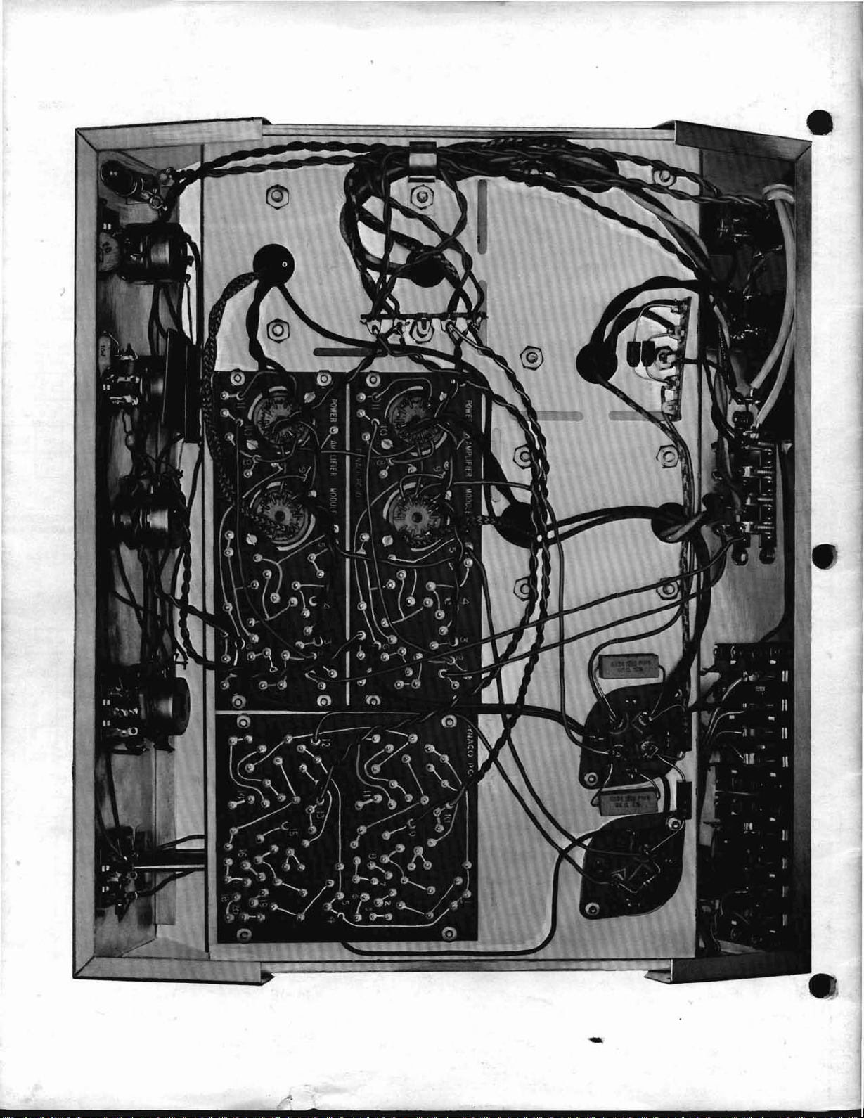
-
s
 Loading...