

Page 1

™
Page 2
N T O W N E R ’ S M A N U A L
W W W . D Y E P A I N T B A L L . C O M
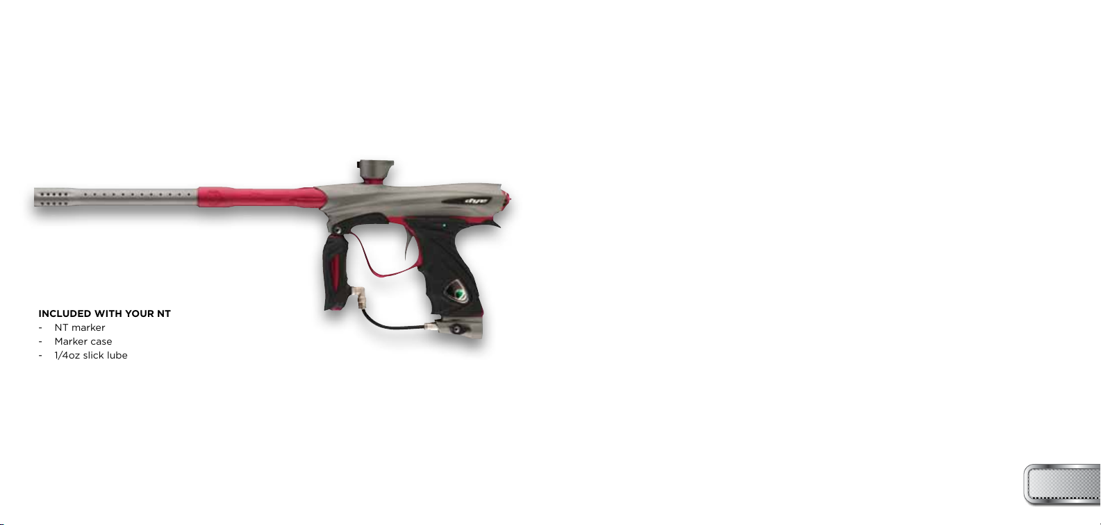
INCLUDED WITH YOUR NT
- NT marker
- Marker case
- 1/4oz slick lube
- Parts kit
- DYE Multi-Tool set
- Shot chamber spacer kit
- Bolt flow insert
- Barrel sock
- Owners manual
- Warranty card
TABLE OF CONTENTS
IMPORTANT SAFETY INSTRUCTIONS AND GUIDELINES . . . . . . . . . . . . . . . . . . . . . . . . . PAGE 02
QUICK REFERENCE . . . . . . . . . . . . . . . . . . . . . . . . . . . . . . . . . . . . . . . . . . . . . . . . . . . . . . . . PAGE 04
ON / OFF AIRPORT-BASIC OPERATION . . . . . . . . . . . . . . . . . . . . . . . . . . . . . . . . . . . . . . PAGE 06
CLAMPING FEEDNECK . . . . . . . . . . . . . . . . . . . . . . . . . . . . . . . . . . . . . . . . . . . . . . . . . . . . . PAGE 06
BOARD SETTINGS AND FUNCTIONS . . . . . . . . . . . . . . . . . . . . . . . . . . . . . . . . . . . . . . . . . PAGE 07
BOOST BOLT OPERATION . . . . . . . . . . . . . . . . . . . . . . . . . . . . . . . . . . . . . . . . . . . . . . . . . . PAGE 13
BOOST BOLT MAINTENANCE. . . . . . . . . . . . . . . . . . . . . . . . . . . . . . . . . . . . . . . . . . . . . . . . PAGE 15
PERFORMANCE AND EFFICIENCY TUNING . . . . . . . . . . . . . . . . . . . . . . . . . . . . . . . . . . . PAGE 20
HYPER3™ . . . . . . . . . . . . . . . . . . . . . . . . . . . . . . . . . . . . . . . . . . . . . . . . . . . . . . . . . . . . . . . . . PAGE 21
STICKY GRIP REMOVAL . . . . . . . . . . . . . . . . . . . . . . . . . . . . . . . . . . . . . . . . . . . . . . . . . . . . PAGE 23
ULTRALITE FRAME . . . . . . . . . . . . . . . . . . . . . . . . . . . . . . . . . . . . . . . . . . . . . . . . . . . . . . . . PAGE 25
TRIGGER ADJUSTMENT . . . . . . . . . . . . . . . . . . . . . . . . . . . . . . . . . . . . . . . . . . . . . . . . . . . . PAGE 27
RUBBER CONTACTS / BUTTON COVER . . . . . . . . . . . . . . . . . . . . . . . . . . . . . . . . . . . . . . . PAGE 29
ANTI-CHOP EYES/ BALL DETENTS . . . . . . . . . . . . . . . . . . . . . . . . . . . . . . . . . . . . . . . . . . PAGE 31
ON/OFF AIRPORT SERVICE . . . . . . . . . . . . . . . . . . . . . . . . . . . . . . . . . . . . . . . . . . . . . . . . PAGE 33
TROUBLE SHOOTING GUIDE . . . . . . . . . . . . . . . . . . . . . . . . . . . . . . . . . . . . . . . . . . . . . . . PAGE 35
WARRANTY INFORMATION . . . . . . . . . . . . . . . . . . . . . . . . . . . . . . . . . . . . . . . . . . . . . . . . PAGE 39
EXPLODED VIEWS . . . . . . . . . . . . . . . . . . . . . . . . . . . . . . . . . . . . . . . . . . . . . . . . . . . . . . . . PAGE 40
DYE Precision, Inc. U.S. AND INT’L PATENTS PENDING.
Covered by one or more of the following U.S. Patents,
5,613,483; 5,881,707; 5,967,133; 6,035,843 and 6,474,326.
W W W . D Y E P A I N T B A L L . C O M
1
Page 3
W A R N I N G
IMPORTANT SAFETY INSTRUCTIONS AND GUIDELINES
W A R N I N G
IMPORTANT SAFETY INSTRUCTIONS AND GUIDELINES
• The NT marker is not a toy. Misuse may cause serious injury or death.
• Please read, understand and follow the directions in the NT
Owner’s manual.
• Eye protection that is designed specifically for paintball and meets
ASTM/CE standards must be worn by user and persons within range.
• Recommend 18 years or older to purchase. Person under 18 must have
adult supervision.
• Always treat the NT marker as if it were loaded and able to fire.
• Only use compressed air or nitrogen gas in the NT marker.
DO NOT USE CO2.
• Do not exceed 850 psi input pressure.
• Ensure all air lines and fittings are tightened and secured before
gassing up the NT.
• Always chronograph the NT marker before playing paintball.
• Never shoot the NT marker at velocities in excess of 300 feet per
second, or at velocities greater than local or national laws allow.
2 3
• Never look into the barrel or breech area of the NT when the marker
is switched on and able to fire.
• Always fit a barrel blocking device to your NT when not in use on the
field of play.
• The owner’s manual should always accompany the product for
reference or in the event of resale and new ownership.
• Do not point the NT marker at anything that you do not intend to
shoot.
• Do not shoot at people, animals, houses, cars or anything not related
to the sport of paintball.
• Do not fire the NT without the Boost™ bolt screwed in completely.
• If you read these instructions and do not fully understand them or are
unsure of your ability to make necessary adjustments properly, call
DYE or your local pro shop for help.
W W W . D Y E P A I N T B A L L . C O MW W W . D Y E P A I N T B A L L . C O M
Page 4
QUICK REFERENCE
USING YOUR MARKER
QUICK REFERENCE
USING YOUR MARKER
AIR SUPPLY
The NT should be operated using air/nitrogen gas only. This air needs to be supplied to the
Hyper3™ in-line regulator at a regulated pressure of no more than 850 psi. The Hyper3™ in-line
regulator comes factory preset at 130psi.
GASSING UP YOUR NT
Screw in your air system to the ON/OFF airport and rotate the side lever counter clockwise
until the internal stop is reached.
TURNING ON YOUR NT
The NT’s power is controlled by two buttons. The top button turns the marker on and off, while
the bottom button turns the eyes on and off. Hold the power button for 3 seconds to turn the
marker on. The LED in the grip will illuminate during the boot sequence.
NOTE: If the eye is not working properly, try replacing the battery.
Blue:: - Boot sequence
Red: - Breech is clear, no ball (eyes on)
Green: - Ball in breech, ready to fire (eyes on)
Blinking Red: - Eyes are off
Blinking Green: - Eye failure (see page 36)
Blinking Blue: - Indicates a low battery, battery should be changed
as soon as possible
HOPPER
To get the best performance out of your NT, it is recommended that you use a motorized
loader, preferably the Rotor™ loader.
4 5
ADJUSTING VELOCITY
The velocity is adjusted through the Hyper3™ in-line regulator. The Hyper3™ in-line is preset from
the factory at approximately 130 psi. This pressure setting should have the marker shooting at
about 285fps. Your paint-to-barrel fit will also have a noticeable effect on your velocity. Make sure
that the paintball fits into the barrel and does not drop through.
NOTE: For the Hyper3™, turning the adjustment screw clockwise, or in, will lower the output
pressure, decreasing the velocity. Turning the adjustment screw counterclockwise, or out, will
raise the output pressure, increasing the velocity.
CHANGING THE BATTERY
The battery is housed on the right side of the grip frame. To access the battery, unhook the
tool-less grips from the grip frame and open to expose the circuit board and battery. For detailed
instructions on how to open the tool-less grips please see page 23. Carefully lift the battery out
of the frame. When inserting a new battery, notice the + and – marks engraved on the gripframe.
The positive lead of the 9V battery goes to the right. The battery should be inserted leads first
and then the bottom of the battery pressed firmly into the frame.
• A low battery will not be able to power both the ACE eye and the trigger
switch, causing ACE eye failure.
• If the battery is low, it may not be able to power the solenoid correctly.
This will affect the NT’s velocity, causing it to become inconsistent and/or low.
W W W . D Y E P A I N T B A L L . C O MW W W . D Y E P A I N T B A L L . C O M
Page 5
ULTRALITE AIRPORT - FEEDNECK
NT BOARD
SETTINGS AND FUNCTIONS
ON/OFF ULTRALITE AIRPORT
The NT comes equipped with an ON/OFF Ultralite Airport
attached to the bottom of the frame. To turn on the gas
supply, rotate the side lever counter clockwise until the
internal stop is reached. To turn off the gas supply, rotate
the side lever clockwise until the other stop is reached. As
you rotate the side lever past the mid point, the residual gas
between the Hyper3™ and the ON/OFF airport will vent. See
page 33 for service information. To remove the UL Airport
from the UL frame see page 26.
CAM LEVER FEED NECK
The Cam Lever Feedneck is adjustable to fit any standard
loader. To adjust the cam locking system, lift the cam lever
away from the feed collar, and rotate the lever clockwise
to tighten or counterclockwise to loosen the grip on the
loader. Once the cam lever is facing in the forward direction,
press the cam lever down against the feed collar to secure
the loader in the feedneck. To loosen the locking system
and remove the loader, lift the cam lever away from the
feed collar. Take care not to over-tighten the cam locking
system. The lever should not be overly difficult to lower into
the locked position.
NOTE: Even with the air supply removed the marker may
have gas inside. Be sure to vent this gas. Make sure there are
no paintballs in the breech and dry fire the marker in a safe
direction.
NOTE: The eye is always activated
when you turn the marker on.
6 7
FIGURE 1
W W W . D Y E P A I N T B A L L . C O MW W W . D Y E P A I N T B A L L . C O M
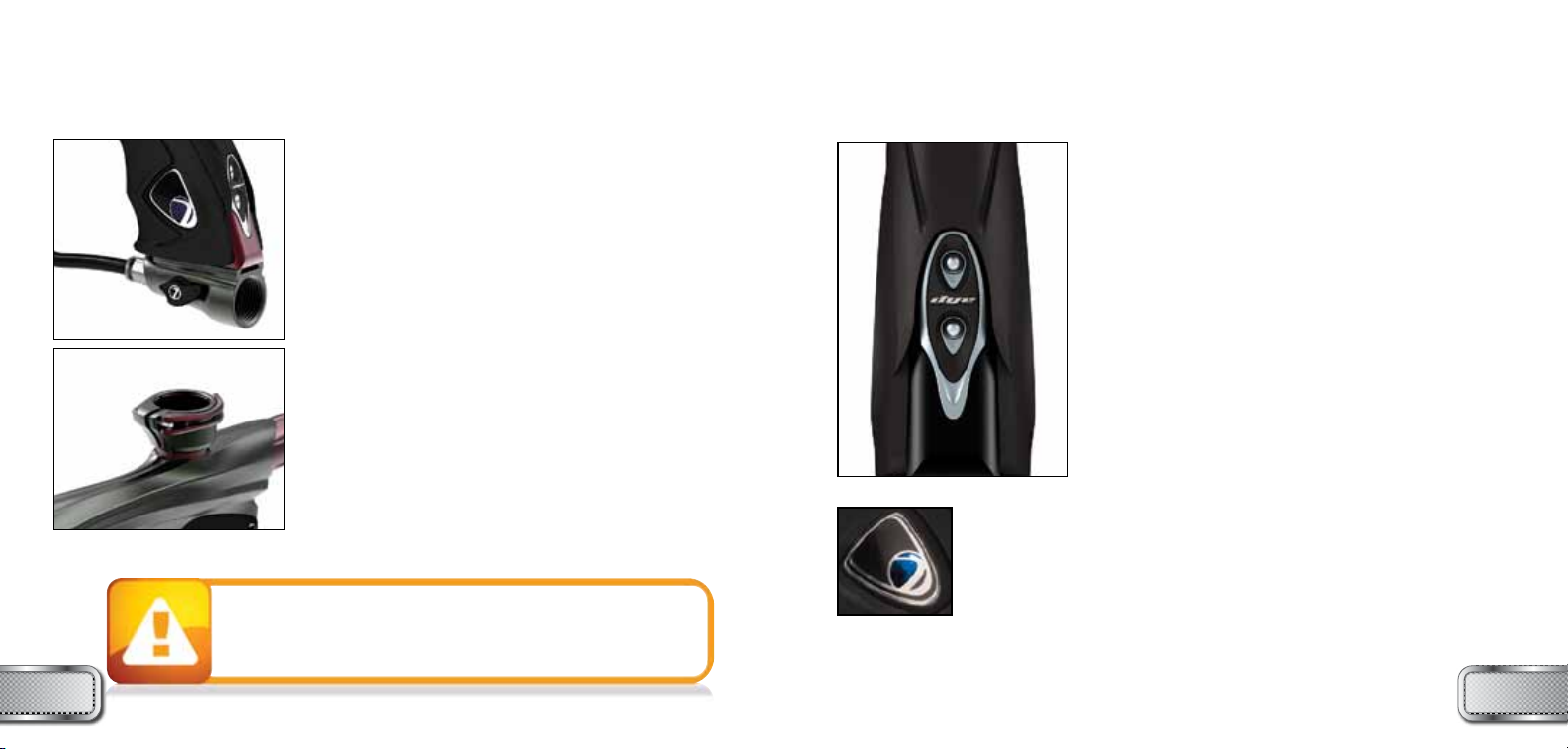
TURNING THE NT ON AND OFF
To turn on the NT, press and hold the power button for 3
seconds (see figure 1) until the LED’s turn blue. The blue
light indicates board boot up. After the boot up sequence,
the LED’s will turn either RED (no ball) or GREEN (ball ready
to fire). To turn the NT off, press and hold the power button
until the LED’s turn off.
NOTE: The NT automatically switches off after 10 minutes
of non-use.
FIRING THE NT
As soon as the marker is turned on and the LED’s turn from
blue to either red or green, the NT is ready to fire. If there
is no ball and the LED’s are RED, you need to hold the
trigger for 1 second to force the NT to fire once. If there is a
paintball inside the breech and the LED is green, just press
the trigger to fire the marker.
LED LIGHT INDICATOR
The NT uses two super bright LED’s mounted on the circuit
board inside the grip frame. These two lights are used to
provide information to the user about the NT. They will
always show the same information and it does not matter
which LED you look at. One is mounted behind the NT logo
on the left side of the grip panels. The other one can be seen
by looking at the top left side of the grip frame while holding
the NT in the position you would while playing a game.
Page 6
NT BOARD
SETTINGS AND FUNCTIONS
NT BOARD
SETTINGS AND FUNCTIONS
BLU E
RED
GRE EN
8 9
When you turn on the marker in normal operation mode with the power
button, the light colors mean the following:
Blue: Boot sequence
Red: Breech is clear, no ball detected inside the NT (eye is on)
Green: Ball in breech, ready to fire (eye on)
Blinking Red: Eye is turned off
Blinking Green: Eye failure, eye is blocked or dirty (see NT Eye, page 36)
Blinking Blue: Indicates a low battery, battery should be
changed as soon as possible
To turn the eyes off, press and hold the lower button until the light begins
flashing red.
To turn the eyes back on, hold the lower button until the LED turns either red
or green.
When servicing your marker:
• Make sure a barrel sock is fitted to the NT.
• Make sure your hopper is removed from the NT.
• Make sure there are no paintballs in the breech of the NT.
• Always remove the first stage regulator and relieve all residual gas pressure from the
NT before disassembly.
• The NT can hold a small residual charge of gas, typically 2 shots, with the first stage
regulator removed. Always discharge the marker in a safe direction to relieve this
residual gas pressure.
FIGURE 1
factory values outlined on pages 10 and 11 once the NT is turned on.
NOTE: User defined settings can’t be saved if DIP switch 1 is in the
down position even if the values are changed in configuration mode.
• The NT is not water resistant. Excess moisture can cause damage to electronic parts.
• Keep the board and all electrical components clean of dirt, paint and moisture.
• To clean the board, use canned air. If a more aggressive cleaning method is needed,
lightly scrub the components with a soft, dry brush.
Heavy scrubbing will damage the board.
W W W . D Y E P A I N T B A L L . C O MW W W . D Y E P A I N T B A L L . C O M
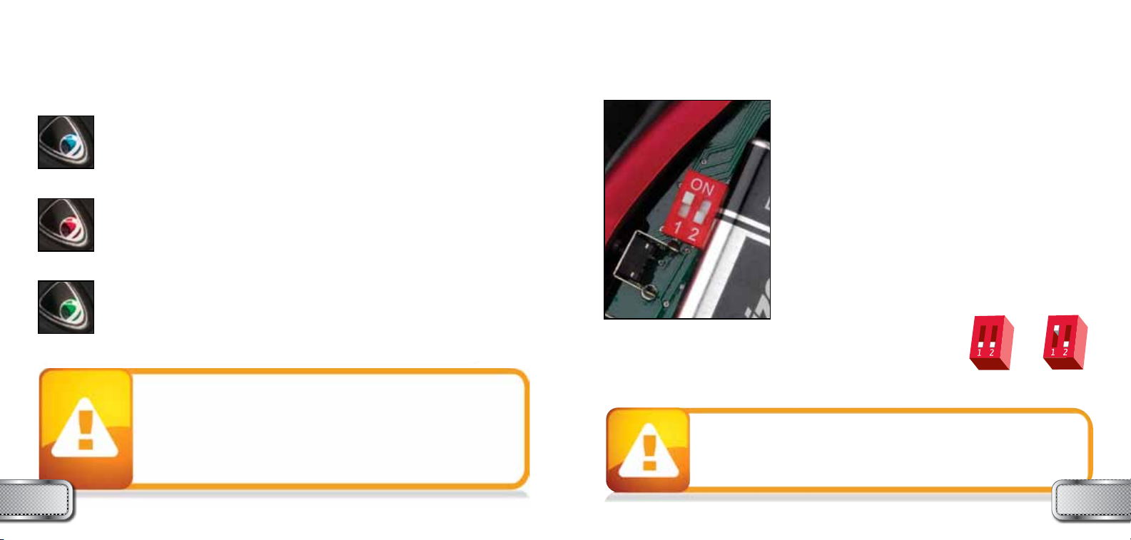
BOARD SETTINGS AND CONFIGURATION MODE
There are four settings you can alter on the NT board with the
DIP switches inside the grip frame (see figure 1):
Trigger Sensitivity - This setting adjusts the delay between
two trigger pulls.
Dwell - This is the time the solenoid is activated for.
ROF - Rate Of Fire - When the eye is deactivated.
Firing Mode - This is the firing mode the NT uses.
There are two DIP switches mounted on the board of the NT
(See figure 1). The first one is used for the factory reset and
the second one is used to access the configuration mode,
where changes to the four settings are made.
DIP switch 1 (factory settings reset) – When DIP switch 1 is
down, settings will be reset to
RESET
SETTINGS
CUSTOMIZED
SETTINGS
Page 7
NT BOARD
SETTINGS AND FUNCTIONS
NT BOARD
SETTINGS AND FUNCTIONS
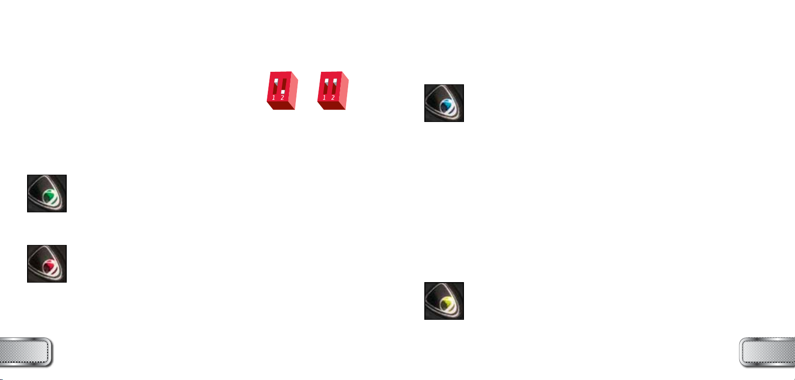
Configuration Mode -The following settings can only be modified
in configuration mode and if dip switch one is in the ON (up)
position. To activate configuration mode, turn your marker off and
set DIP switch 2 to the ON position. Next, turn your marker on.
The LEDs cycle through all colors for one second to indicate
that you have entered the configuration mode.
To cycle through different settings, pull and release the trigger. Configuration mode has 4 settings that can be changed.
Green - Trigger Sensitivity Values 1 - 20 (factory default 3)
Trigger sensitivity is the amount of time that the trigger has to be
released before the next trigger pull is allowed. In some situations
with too low of a value, the NT can register more trigger pulls than
what was actually pulled. This can cause the NT to shoot full auto,
even in semi-automatic mode. To fix this, adjust trigger sensitivity
setting higher.
Red - Dwell Values 0 - 20 (factory default 6)
Dwell is the amount of time that the solenoid will be activated during
each shot.
• It is not recommended to adjust the Dwell.
• If you choose to adjust the Dwell and use too low of setting the NT
will not cycle.
• If you choose to adjust the Dwell and use too high of setting the
NT will begin to double fire.
NORMal
MODE
CONfIGURaTION
MODE
10 11
Blue - Rate Of Fire (ROF) Values 1 - 45 (factory default 12.5 bps)
Yellow - Firing Mode Values 1 - 4 (default 1)
Value 2 - Millennium Mode
Value 3 - PSP Mode
Value 4 - Full Auto
The ROF setting is used to set the maximum rate of fire of the NT.
The values do not correspond directly to a certain Balls
Per Second.
The factory setting is 20 (12.5 bps).
This setting changes the firing mode of the NT. Default is
semiautomatic. In the semiautomatic mode, one trigger pull
shoots out one paintball. The PSP mode and the Millennium
mode follow the rules of the paintball tournament series.
Value 1 - Semiautomatic Mode
W W W . D Y E P A I N T B A L L . C O MW W W . D Y E P A I N T B A L L . C O M
1 9.80 BPS
2 9.90 BPS
3 10.0 BPS
4 10.10 BPS
5 10.20 BPS
6 10.30 BPS
7 10.41 BPS
8 10.52 BPS
9 10.63 BPS
10 10.75 BPS
11 10.86 BPS
12 10.98 BPS
13 11.11 BPS
14 11.62 BPS
15 11.76 BPS
16 11.90 BPS
17 12.04 BPS
18 12.19 BPS
19 12.34 BPS
20 12.50 BPS
21 12.65 BPS
22 12.82 BPS
23 12.98 BPS
24 13.15 BPS
25 13.33 BPS
26 13.51 BPS
27 13.69 BPS
28 13.88 BPS
29 14.08 BPS
30 14.28 BPS
31 14.49 BPS
32 14.70 BPS
33 14.92 BPS
34 15.15 BPS
35 15.38 BPS
36 15.62 BPS
37 15.87 BPS
38 16.12 BPS
39 16.39 BPS
40 16.66 BPS
41 20.0 BPS
42 22.22 BPS
43 25.0 BPS
44 28.57 BPS
45 33.33 BPS
Page 8

NT BOARD
BATTERY
NOTE: You cannot turn your marker off with the power button when the marker is in
configuration mode. You must first set DIP switch 2 to the OFF position.
TO CHANGE A VALUE OF A SETTING
1. While in the configuration mode and Dip switch number 1 is on, choose the color you wish to
change by pulling the trigger.
2. When the LED indicates the color you wish to change, pull and hold the trigger until the LED
starts to flash.
3. The LED will flash as many times as the previous setting was and it will then turn off. Now pull
the trigger as many times as you wish the new setting to be.
4. When done, the LED will cycle through all the colors again to indicate setting was saved and
• A low battery will not be able to power both the ACE eye and the trigger switch,
causing ACE eye failure.
• If the battery is low, it may not be able to power the solenoid correctly. This will
affect the NT’s velocity, causing it to become inconsistent and/or low.
turn back to green. You can now change another setting or quit the
configuration mode.
5. To exit configuration mode, set DIP 2 to the OFF position.
BATTERY
Standard 9V batteries will last for about 40,000 shots. Please be
aware that there are substantial differences in performance between
different brands of batteries. Use of high quality alkaline or lithium
ion batteries is recommended for maximum battery life. If you plan
not to use your marker for a long period of time (a month), it is
recommended that you remove the battery from the marker.
An intermittent blinking blue light indicates a low battery. A low
battery can cause the marker to malfunction.
BOOST BOLT
ASSEMBLY AND MAINTENANCE
1 2 3 4 5
BOOST™ BOLT COMPONENTS
The NT bolt has five basic components:
1. Cylinder
2. Soft-tipped Bolt assembly
3. Plunger
4. Spool
5. Backcap/ Bleed assembly
BOOST™ BOLT OPERATION
To achieve top performance from
your NT, it is important to have basic
understanding of the patented NT
bolt operation.
The design consists of three housing
components threaded together and three
floating components, two of which move
when the bolt cycles.
Air is supplied to the Boost Bolt Kit at two
points. The primary air supply is introduced to the bolt kit at the front of the Cylinder between
the two 020 O-rings. The primary air supply is responsible for three main operations: holding the
bolt in the rear position, fill the shot chamber, and fill the spool dump chamber.
The secondary air supply is controlled by the solenoid. When the trigger is activated and the
solenoid is energized, air is supplied between the two 020 O-rings on the Plunger. The secondary
air supply is responsible for driving the spool forward when the NT is fired.
When the bolt is in the rear position, the primary air supply travels from the front of the bolt kit
to the rear of the bolt kit filling the shot chamber. At the same time small transfer holes in the
Plunger behind the 014 O-ring allow the primary air supply to fill the spool dump chamber.
Forward Position
Back Position
12 13
W W W . D Y E P A I N T B A L L . C O MW W W . D Y E P A I N T B A L L . C O M
Page 9

BOOST BOLT
ASSEMBLY AND MAINTENANCE
BOOST BOLT
ASSEMBLY AND MAINTENANCE
With the bolt in the rear “at rest” position, the primary air supply produces an imbalanced
rearward dominant force, holding the bolt in the rear position. When the NT is fired the solenoid
is energized and allows the secondary air supply to enter the Plunger between the two 020
O-rings. The secondary air supply applies force on the back of the spool, driving it forward. As
the spool moves forward the primary air supply is cut off to the spool, and the air in the spool
dump chamber is transferred between the 012 O-ring and 014 O-ring on the outside of the
plunger. This influx of air is enough to create a forward dominate force on the bolt, and begins to
drive the bolt forward.
Because the primary air supply to the spool dump chamber is closed before the spool dump
chamber is transferred only a set volume of air is used each cycle which ensures no air is wasted.
When the bolt begins to move forward the 016 bolt sail O-ring seals inside the cylinder, cutting
off the primary air supply to the shot chamber. The bolt continues moving forward and drops off
the 014 O-ring on the Plunger, which creates a boost in forward force and greatly increases the
speed on the bolt. As the bolt reaches it’s most forward position it drops off the 012 O-ring on
the Plunger, and releases the shot chamber down the bolt and fires the paintball.
The self-closing valve is activated before all of the gas in the shot chamber is used,
thus increasing efficiency.
As the shot chamber is released behind the ball the forward force drops and the rearward force
created by the primary air supply quickly becomes the dominant force, and the bolt begins to
return to the rear “at rest” position. At this time, with the spool dump chamber empty and the
solenoid no longer delivering air to the back of the spool, the spool is returned to its rear position
by the spool return spring. With the bolt and spool in the rear position the Boost Bolt Kit is ready
to be cycled again.
14 15
BOLT MAINTENANCE
Regular Boost bolt maintenance is vital to the performance of the NT. Dirt or debris can reduce
O-ring life and ultimately cause the NT to malfunction or leak. The NT will continue to function
without lube for a short period of time, however the NT’s efficiency and performance may be
affected, and o-ring life will be shortened.
Bolt maintenance should always be performed with the gun de-gassed.
STANDARD MAINTENANCE
Remove the bolt with a 1/4” Allen wrench. Only one and a half counterclockwise rotations are
required so that the bolt kit can be pulled out. Check and remove any foreign debris, such as dirt.
Check that there is a thin layer of lube coating all visible O-rings. Apply a small amount of DYE
Slick Lube™ as necessary, excessive lube will not help the NT’s performance.
It is also recommended to inspect the detents, eye pipe, and eye assembly. Make sure the eye pipe
is clean of any dirt or broken paint that may cause the eyes to function improperly. Inspect the
ball detents; look for any excessive wear that may prevent the detents from working as intended.
See pages 18-19 for detailed information.
When servicing your marker:
• Make sure a barrel sock is fitted to the NT.
• Make sure your hopper is removed from the NT.
• Make sure there are no paintballs in the breech of the NT.
• Always remove the first stage regulator and relieve all residual gas pressure from the
NT before disassembly.
• The NT can hold a small residual charge of gas, typically 2 shots, with the first stage
regulator removed. Always discharge the marker in a safe direction to relieve
this residual gas pressure.
W W W . D Y E P A I N T B A L L . C O MW W W . D Y E P A I N T B A L L . C O M
Page 10

BOOST BOLT
ASSEMBLY AND MAINTENANCE
BOOST BOLT
ASSEMBLY AND MAINTENANCE
BOLT MAINTENANCE TIMELINE
In addition to performing regular maintenance, it is a good idea to follow the following bolt
maintenance timeline:
Shots Corresponding cases of paint Action
10000 5 Only standard maintenance required
20000 10 Only standard maintenance required
30000 15 Only standard maintenance required
40000 20 Only standard maintenance required
50000 25 Replace 111 Bolt Bumper O-Ring
60000 30 Only standard maintenance required
70000 35 Replace 016 Sail O-Ring, 012 and 014 Plunger
O-rings
80000 40 Replace 017 Cylinder O-ring
90000 45 Replace 010 Spool O-rings
100000 50 Replace 111 Bolt Bumper O-Ring
There are seven static O-rings in the Boost Bolt Kit (5x 020, 2x 011) that should be replaced if the
bolt kit is removed and installed frequently. During standard maintenance check these O-rings for
damage, but for regular use these O-rings rarely need to be replaced.
After 150,000 shots (or 75 cases of paint) it is a good idea to remove all of the O-rings in the
Boost Bolt Kit, and rinse bolt parts in warm water. Once the parts are dry, assemble the Boost Bolt
Kit using all new O-rings. Apply a small amount of DYE Slick Lube™ to all parts. At this time,
it is important to check the spool bumpers as well as the Bolt Flow Insert for excessive
wear.
COMPLETE BOLT DISASSEMBLY
To separate all Boost bolt parts begin by removing the Boost Bolt Kit with a 1/4” Allen wrench.
Only one and a half counterclockwise rotations are required so that the bolt kit can be pulled out.
• Remove the 014 Bolt tip O-ring with a pick supplied on the DYE Multi-Tool
• Unscrew the Cylinder from the Plunger by rotating it counter-clockwise and set aside
• Pull the bolt off the plunger
• Remove the Bolt Flow Insert, use a 1/4” Allen wrench or dowel to push the
Bolt Flow Insert through the Bolt Soft Tip towards the back of the bolt
• Once the Bolt Flow Insert is removed, pull the soft bolt tip out the front of the bolt
• Separate the Plunger and Spacer Rod by using a 7/16” wrench One is included in the DYE
Multi-Tool. Secure the Spacer Rod with the wrench, and unscrew the Plunger by hand, rotating
he Plunger counter-clockwise. If the threads are locked together, a 5/64” Allen wrench can
be inserted into the Solenoid air transfer holes on the Plunger, to get a better grip
• The Spool can be removed by pulling it from the Plunger with a pair of needle-nose pliers, or
by inserting a long Allen wrench or dowel into the front of the Plunger. Simply shake or gently
knock the Plunger against the table to remove the Spool Spring
• Remove the Backcap from the Spacer rod, use a 7/16” wrench to hold the Spacer Rod and
insert a 1/4” Allen wrench into the Backcap. Rotate the Spacer Rod counter-clockwise until
released from the Backcap
• The Bleed Button can be removed from the Spacer Rod with a pair of needle-nose pliers
• To separate the Backcap and Backcap Cover use a 3/32” Allen wrench, and unscrew the three
retaining screws. This level of disassembly is not needed for any maintenance
W W W . D Y E P A I N T B A L L . C O MW W W . D Y E P A I N T B A L L . C O M
1716
Page 11

BOOST BOLT
ASSEMBLY AND MAINTENANCE
ASSEMBLY
• Insert the Bleed Button into the Spacer Rod and screw the Spacer Rod into the Backcap using
a 1/4” Allen wrench and 7/16” wrench to tighten snugly. Take care not to over-tighten the two
pieces together. Excessive force may twist, warp, and ultimately break the Spacer Rod.
• Insert the Spool Spring and Spool into the Plunger. Make sure that the Spool is facing the
correct direction (see page 19).
• Screw the Spacer Rod into the Plunger. It is only necessary to hand tighten the Spacer Rod
and Plunger.
• Insert the Bolt Soft Tip into the front of the Bolt.
• Insert the Bolt Flow Insert from the back of the bolt, with the larger diameter of the insert
facing rearward.
• Push the bolt onto the Plunger and screw on the Cylinder only hand tight. Replace the 014 Bolt
tip O-ring, and screw the Boost Bolt Kit back into the body using a 1/4” Allen wrench.
BACKCAP/ BLEED ASSEMBLY
The Bleed assembly consists of the Spacer Rod, the Backcap, Backcap Cover, and Bleed Button.
The purpose of the bleed assembly is to offer a way to de-gas your NT without having to fire a
shot. It also acts as safety mechanism so that a tool cannot be used to unscrew the bolt kit while
there is gas in the NT.
To completely de-gas the NT, simply deactivate the ON/OFF UL Airport located on the bottom of
the gripframe and then press the Bleed Button until all gas is released.
NOTE: LOW OR ERRATIC VELOCITY MAY BE DUE TO A LOW BATTERY NOT SUPPLYING
AMPLE ELECTRICAL CURRENT TO THE SOLENOID. IN THIS CASE, CHANGE THE BATTERY.
H D
I
E F
3
Component:
1 Cylinder 4b Spool Spring
2a Bolt 5a Spacer Rod
2b Soft Bolt Tip 5b Bleed Button
2c Bolt Flow Insert 5c Backcap
3 Plunger 5d Backcap Cover
4a Spool
I
4b
1
B B C
4a
BOOST BOLT
ASSEMBLY AND MAINTENANCE
FI
2b 2c
O-rings:
A. 005 F.
B.
C.
D.
E.
2a
5a 5b
010
011
111
012
G
C
A
G.
H.
I.
I
5c 5d
014
016
017
020
W W W . D Y E P A I N T B A L L . C O MW W W . D Y E P A I N T B A L L . C O M
1918
Page 12

PERFORMANCE & EFFICIENCY TUNING
HYPER3™ IN-LINE REGULATOR
ADJUSTMENTS AND MAINTENANCE
From the factory the DYE NT is tuned to give you a balance of efficiency, consistency, and
shooting comfort. The NT comes with a shot chamber spacer kit and two bolt flow inserts to help
you tune your NT to your specific requirements.
The NT with a stock shot chamber of 2.23 cubic inches has a standard operating pressure
of about 130psi @ 285fps. A factory tuned NT will yield approximately 1500 shots off a
68ci/4500psi compressed air tank. Your air efficiency can easily be increased if your playing
needs require it.
To increase air efficiency :
1 - Remove the bolt kit
2 - Start with mounting the spacer body onto the spacer rod
3 - Add as many spacers as you wish to achieve your desired performance level.
4 - If you choose to use more than the spacer body and one volume ring it is recommended to use the Blue bolt
flow insert. (See pages 17-19 for details)
5 - Make sure the bolt kit is assembled properly before installing it into the body (See pages 17-19 for details)
As you reduce the air volume in the shot chamber the Hyper3 regulator pressure will need to be
raised to maintain velocity. By doing so there will be a change in shooting comfort, the NT’s recoil
will increase, and it’s sound signature will become modified.
As you tune your gun for increased air efficiency you may notice a small decrease in your velocity
consistency. The less air that is used, the more ball to barrel fit, and paintball quality will affect
your velocity. At this point the difference in barrel friction from ball to ball will result in a more
noticeable fluctuation in velocity. Generally a tighter fitting ball to barrel match will give you a
more consistent amount of friction and velocity.
Changing the flow insert will aid in increased efficiency and help maintain shooting comfort.
Note: If you intend on using the NT at velocities lower than 250fps it is recommended
to use all four shot chamber spacer rings, and the blue Flow Insert in order to
maintain sufficient forces in the bolt for proper function.
010 BN 70 007 UR 90 011 BN 70
SEAT RETAINERSWIVELBOTTOM CAP TOP CAPBODY
USAGE
Carefully connect the 1/4” macroline from the airport fitting into the Hyper3™ elbow fitting.
The macroline should be cut straight with a sharp knife to prevent leaks.
ADJUSTMENTS
The Hyper3™ regulator is adjusted by using a 3/16” Allen wrench. With the seat retainer screwed
completely clockwise, the Hyper3™ will be set to 20 psi. Each 180 degree turn counterclockwise
will increase the pressure between 15-20 psi. The stock setting is 130 psi
(about 3 complete 360 degree turns out), which should result in the NT shooting velocities of
about 285fps.
MAINTENANCE
The Hyper3™ regulator requires little maintenance from regular use. The seat should be replaced
every 6 months or 60,000 shots. Shooting the NT a few times between each small adjustment
to the regulator, will lengthen the life of the seat. Also, O-rings and the seat may wear rapidly if
excessive dirt or sand is allowed into the regulator, so the Hyper3™ should be kept clean.
W W W . D Y E P A I N T B A L L . C O MW W W . D Y E P A I N T B A L L . C O M
013 BN 70
REGULATOR SEAT
2120
Page 13

HYPER3™ IN-LINE REGULATOR
ADJUSTMENTS AND MAINTENANCE
NOTE: For the Hyper3™, turning the adjustment screw clockwise, or in, will lower the output
pressure, decreasing the velocity. Turning the adjustment screw counterclockwise, or out, will
raise the output pressure, increasing the velocity.
HYPER3™ REGULATOR DIS-ASSEMBLY INSTRUCTIONS
The rubber sleeve on the outside of the Hyper3™ does not need to be removed to disassemble
the seat assembly, but may make the process easier. Begin by inserting a
into the topcap and a
the Hyper3™. If the topcap begins to unscrew, try tightening the regulator back together and
unscrewing again. Sometimes it is necessary to use a vice to hold the Hyper3™ body to remove
the bottom cap. The brass seat retainer and swivel can now be removed from the regulator. If the
swivel is stuck, the elbow fitting may need to be removed.
To change the seat, remove the seat retainer from the regulator body. Use a dental pick or sharp
object to remove the old seat from the retainer and replace it with a new one. Use a flat object to
press it into place.
Any further disassembly should be performed by a trained tech. If you have any questions please
call the DYE tech line.
REASSEMBLY
Grease the 010 O-ring on the seat retainer and the two 013 O-rings on the Hyper3™ body. Insert
the seat retainer being careful to not screw it in too tightly. Slide the swivel gently back onto
the body and screw on the bottom cap. If the elbow fitting was removed, use thread sealant and
snugly screw it back into the swivel making sure that the swivel can rotate freely.
5
⁄16” Allen wrench into the bottom cap. Unscrew the bottom cap from
• The Hyper3™ can hold a small residual charge of gas, typically 1 shot.
Always discharge the marker in a safe direction to relieve this residual gas pressure.
• Improper stacking of shims will cause failure of the regulator and possible damage
to the NT.
• Excessive dirt and debris can affect the Hyper3™’s performance and increase the
need for service.
22 23
3
⁄16” Allen wrench
1. Pull the upper back corner of the grips away from
the gripframe with your thumb. Allowing the rear tabs
to clear the frame.
3. The top portion of the grips should be free from the
gripframe.
W W W . D Y E P A I N T B A L L . C O MW W W . D Y E P A I N T B A L L . C O M
2. While pulling with your thumb, using your index
finger, to push the grips toward you.
4. Grab a hold of the inside of the grips with your
fingers, using your palm on the outside
surface of the grip.
STICKY GRIP
GRIP REMOVAL
Page 14

STICKY GRIP
ULTRALITE FRAME
GRIP REMOVAL
REMOVING ULTRALITE FRAME FROM THE NT
If there is ever a need to remove the Ultralite frame from the NT make sure to follow these steps.
• Unhook and open the right side of the tool-less grip to expose the circuit board.
• Disconnect the solenoid wire and the eye wire from their sockets by GENTLY pulling them out.
• Using a 3/32” Allen wrench, turn the front frame screw counterclockwise 2 full turns.
• Finally, using a 3/32” Allen wrench turn the rear frame screw completely out, by turning it
counterclockwise. The frame can now be removed from the NT.
INSTALLING THE ULTRALITE FRAME ON THE NT
To reinstall the Ultralite grip frame on the NT make sure to follow these steps.
• Make sure the solenoid and eye wires are secured to the under side of the body by the two
5. Push the grips toward the barrel tip. 6. In doing so, you will have released the last three
7. Repeat instructions for reverse side and slide the
grips off the frame.
locking tabs that are under the molded finger grooves.
INSTALL NT STICKY TOOL-LESS GRIPS
• Insert the bottom rear locking hook into the
retaining hole at the bottom rear of the UL
frame.
• Lock the hook into place by sliding the grip
panel forward.
• Press the three locking tabs under the
molded finger groves into the corresponding
slots on the frame’s front strap.
• Pull the top of the grip panel back in order
to allow the front top locking hook to drop
into the frame.
• Push the top of the grip panel forward to
lock the top front hook into place.
• Press down on the upper rear corner to seat
the upper retaining post into position.
24 25
orange retaining clips. Route the eye wires under both clips. Route the solenoid wire over the
top of the solenoid and under only the rear-retaining clip. This will help ensure the wires do not
get pinched between the body and frame, and feed smoothly into the frame.
• Feed the eye and solenoid wires through the grip frame, and slide the gripframe into place. It
may be necessary to slide the front frame screw into the frame if it has fallen out during frame
removal.
• Push the back of the frame onto the body taking care not to pinch either the eye or solenoid
wires between the gripframe and the body.
• Use a 3/32” Allen wrench to screw in the rear frame screw by turning it clockwise.
• Use a 3/32” Allen wrench tighten the from frame screw by turning it clockwise.
NOTE: For exploded view
of UL Frame and parts list
see page 40
W W W . D Y E P A I N T B A L L . C O MW W W . D Y E P A I N T B A L L . C O M
Page 15

ULTRALITE FRAME
TRIGGER ADJUSTMENT
INTEGRATED LOCKING DOVETAIL FEATURE
The Ultralite frame comes equipped with an integrated locking dovetail. There is a horizontal
locking screw located on the bottom right side of the Ultralite frame. It can be accessed with a 1⁄8”
Allen wrench through a hole in the grip panel. To unlock the UL Airport attached to the dovetail
of the frame, turn the locking screw counterclockwise one full turn and slide the part off the rail.
To attach a part to the rail, slide the part on and turn the locking screw clockwise until the part
is firmly locked in place. If you choose to use a drop forward or other kind of airport mounting
system there are standard 10-32 mounting screw holes located on the bottom of the UL frame.
There is no reason to disassemble the dovetail locking system if you choose not to use it.
NOTE: Be sure that the frame and trigger assembly are kept clean. If there is excess dirt or
paint build up around the trigger, the trigger will no longer move freely. In addition, paint and
dirt can cause the microswitch to not function properly or fail.
NOTE: Be sure you do not pinch the wires between the frame and the body when reattaching
the frame and body.
NOTE: The frame screws should not be overly difficult to screw into the body. If strong
resistance is felt, stop, back the screw all the way out, and try again to avoid stripping either
the threads or the head of the screw.
26 27
ADJUSTING YOUR TRIGGER
The trigger’s forward and over travel, spring tension, and
reach are fully adjustable so that you can fine-tune the
trigger to your exact liking. You do not need to remove
the frame or grip from the gun in order to adjust the
trigger pull.
There are two adjustment screws located on the left side
of the Ultralite frame and one adjustment screw behind
the trigger. The two screws on the side of the frame
adjust the travel of the trigger.
The one located behind the trigger is used to change the
tension of the trigger spring.
TO ADJUST TRIGGER TRAVEL (SEE FIGURE 1)
5
⁄64” Allen wrench to make the desired adjustments.
Use a
• The lower screw controls the forward travel. Screwing it in will shorten the trigger’s length
of pull.
NOTE: If this screw is adjusted too far, the switch will be held down at all times and the marker
will not fire.
• The upper screw controls the over travel. By turning this screw you can adjust how far the
trigger will travel after it reaches the firing point.
NOTE: If this screw is adjusted too far, the trigger will not be allowed to travel far enough to
depress the switch and fire the marker.
TO ADJUST SPRING TENSION (SEE FIGURE 1)
5
⁄64” Allen wrench to make the desired adjustment. The adjustment is made by pushing
• Use a
the Allen wrench through a hole in the trigger .
• To make the trigger pull stiffer, turn the Allen wrench clockwise, or in.
• To make the trigger pull lighter, turn the Allen wrench counterclockwise, or out.
1
2
3
W W W . D Y E P A I N T B A L L . C O MW W W . D Y E P A I N T B A L L . C O M
3
FIGURE 1FIGURE 1
2
1
Page 16

TRIGGER ADJUSTMENT
CONTACT PADS & BUTTON COVER
FIGURE 2
4
NOTE: The spring tension adjustment (outlined on page 27) should be set while the trigger’s
reach is situated in either the rear position or the loose position so the spring tension adjust
screw can be externally accessed.
• Be sure the trigger is not adjusted to the point where it is too
sensitive and may cause accidental discharge of the marker
• Removing the trigger spring may cause premature wear on the
microswitch, resulting in failure.
ULTRALITE REACH TRIGGER
The NT has a new external reach adjustment
for the Ultralite trigger.
This adjustment changes the angle that the
trigger sits without the need to take off the
gripframe or Sticky Grip.
TO ADJUST TRIGGER REACH
(SEE FIGURES 1 AND 2)
To adjust, simply loosen the two 6-32
4
screws using a 1/16” Allen wrench. You
do not have to remove the screws from the
trigger. Now the front of the trigger (shown
in green) should rotate freely while the
back of the trigger (shown in blue) remains
relatively stationary. When the desired reach
angle has been achieved, tighten the two
6-32 screws snugly. Be careful not to over
tighten and strip the Allen wrench or screws.
CONTACT PAD, CONTACT GRIP AND BUTTON COVER
The front rubber Contact Pad and Contact Grip are mounted to the Ultralite frame. It is not
necessary to remove the two contact pads when removing the frame from the body. The only
reason to remove the contact points is for general cleaning of built up dirt or paint.
REMOVAL OF CONTACT PADS
• Remove frame from body. Follow frame removal instructions on page 25
• Use a 3/32 Allen wrench to remove the front contact pad
• Use a 1/16 Allen wrench to remove the contact grip
W W W . D Y E P A I N T B A L L . C O MW W W . D Y E P A I N T B A L L . C O M
2928
Page 17

CONTACT PADS & BUTTON COVER
ANTI CHOP EYES/BALL DETENTS
MAINTENANCE AND CHANGING
BUTTON COVER REMOVAL
It may become necessary to remove the button cover if the buttons get stuck due to built up
paint or dirt.
• Unhook and open both sides of the tool-less sticky grips.
• Remove Hyper3™ regulator.
• Remove battery; use a small Phillips screwdriver. One can be found in the DYE Multi-Tool
that is included with the NT.
• Unscrew the mounting screw found on the inside of the frame; use a Phillips screwdriver.
• To access the screw insert the screwdriver through the middle slot on the frame’s front strap.
• Once the screw is removed it may be necessary to push the button cover out from the back.
Apply force to the lower button. This will push the cover out from the center and help prevent
binding.
• Take care not to lose the buttons as you remove the cover.
• Once removed, clean the button cover, buttons, and frame.
• When assembling the button retaining cover make sure the rounded ends of the
buttons face outward.
30 31
ANTI CHOP EYES
The Anti Chop Eye (ACE) system will prevent the NT from chopping paint by not allowing the
marker to fire until a ball is fully seated in front of the bolt. The eyes use a light beam across the
breech. On one side there is a transmitter, and on the opposite side a receiver. In order for the
marker to fire with the eyes turned on, the signal between the two eyes must be broken. After
every shot, before the next ball drops in the breech, the eye transmitter and receiver must see each
other. If there is a malfunction, the LED’s on the board will start blinking green. This means that the
receiver and the emitter do not see each other. If this is the case, there are normally two reasons.
Either there is dirt, paint or grease blocking the beam, or the battery is so low there is not enough
power to create a strong enough light beam.
NOTE: IF THE BATTERY IS LOW, THE MARKER MAY ACT AS IF THE EYES ARE DIRTY OR NOT
FIRE AT ALL. IN THIS CASE, REPLACE THE BATTERY.
SELF CLEANING EYE FEATURE
The NT is equipped with a self cleaning eye feature. There is a clear poly-carbonate sleeve mounted
inside the breech of the gun covering the eyes. When the bolt tip O-ring passes through the eye
pipe, it sweeps off any dirt, grease or paint that could be blocking the eyes. Normally, it is enough to
just fire the NT to clean anything blocking the eyes. If this does not clear the blockage, use a swab
to clean the inside of the breech.
For a more thorough cleaning, pull the eye pipe with the ball detents out the front of the breech.
With the eye pipe out, use a swab to clean the breech. This should be enough to clean the eye
system. If the system needs further cleaning, pull out the eye carrier and eye wires through the feed
neck. To prevent damaging the eye wires, it is best to remove the frame and disconnect the eye
wires from the board. Use a soft rag and q-tips to clean off any built up paint or grease.
When re-assembling the eye pipe assembly, work backwards from disassembly. The eye pipe is
keyed into the breech and can only go in one way.
W W W . D Y E P A I N T B A L L . C O MW W W . D Y E P A I N T B A L L . C O M
Page 18

ANTI CHOP EYES/BALL DETENTS
ON/OFF AIRPORT DETAIL
MAINTENANCE AND CHANGING
CHANGING BALL DETENTS
The ball detent system is clipped to the outside of the eye pipe. The ball detent system needs little
or no maintenance. The detents should easily flex out of the way with little force, such as a paintball
moving past. If you are experiencing
double feeding or chopping, check
the condition of your ball detents
with your finger to make sure they
are not broken and that they move
in and out of the breech freely. If
excessive broken paint or dirt has
jammed your ball detents, remove
the eye pipe/detent system from
the front of the NT and unclip the
detents for a thorough cleaning.
Reinstall the detents and eye pipe
after you have sufficiently cleaned
the detents and breech.
Be careful not to over-flex the
detents when handling them.
Excessive flexing could break or
damage the detents.
NOTE: TAKE CARE WHEN REPLACING THE EYE PIPE. BE CAREFUL THAT THE DETENT
CLIP IS FULLY SEATED ONTO THE EYE PIPE
.
32 33
ON/OFF AIRPORT DISASSEMBLY AND ASSEMBLY
Remove Pin housing assembly
To disassemble the NT airport use the airport tool included on the DYE Multi-Tool included
with the NT.
• Insert the airport tool into the Pin Housing and turn counterclockwise 3-4 revolutions. Note
that the airport lever must be in the OFF position for the tool to grab the housing. Remove
housing out of the airport body.
• The pin and 005 O-ring may or may not come out with the housing, if necessary use a pair of
needle-nosed pliers to pull the pin out and a dental pick to remove the 005 O-ring.
Install Pin housing assembly
• Coat the 005 O-ring in lube and drop it into the airport body. Use a 1/4” Allen wrench to fully
seat the O-ring in place by pushing gently on it.
• Insert the Pin into the Pin Housing from the backside.
• Place the housing onto the airport tool and insert the housing into the airport body.
• Turn clockwise until the Pin Housing fits snugly into the airport body.
*If the airport tool is not available, a pair of needle-nose pliers can be used to unscrew the
Pin Housing. Just take care to not scratch or damage the threads or Pin Housing.
W W W . D Y E P A I N T B A L L . C O MW W W . D Y E P A I N T B A L L . C O M
Page 19

ON/OFF AIRPORT DETAIL
Remove the airport lever and internal cam
• Remove the DYE sphere jewel located in the middle of the airport lever.
• Use a 1/16” Allen wrench to unscrew the retaining screw and remove the screw and lever.
• Insert a dental pick into the small slot to pull out the 010 retaining O-ring. If the Pin and Pin
housing have been removed, the cam should come out with no resistance. If the Pin and Pin
Housing are installed in the airport body, the cam must be in the ON position so it can be
removed.
Install airport lever and cam
• Make sure that the Pin is not protruding into the area where the Cam sits.
• Use a dental pick or small Allen wrench to push the pin out of the bore if necessary.
• Drop the Cam into the airport body such that the slot face upwards and rotate it clockwise until
it drops in place and hits the internal stop.
• Insert the 010 retaining O-ring into the groove and gently work it in place with a dental pick or
small screwdriver.
• Push the Lever into the Cam slot so that the Lever is facing down, or in the OFF position.
• Install the retaining screw with a 1/16” Allen wrench and tighten firmly. Turn the Lever counter clockwise until it hits the internal stop. Replace the jewel on the Retaining Screw so that the
Dye sphere is correctly oriented.
NOTE: For exploded view of airport and parts list see page 41
TROUBLE SHOOTING GUIDE
AIR LEAKS
AIR LEAKING FROM THE BACK OF AIRPORT
• Check the O-ring on the Air system. If needed
change the O-ring and try again. The O-ring
normally used is 015 O-ring but some
manufacturers might use a different size. Consult
the manual of the air system you are using.
AIR LEAKING FROM THE FRONT OF
AIRPORT
• Check that the hose connector is tight. Remove
the hose from the connector by pushing towards
the connector and pull out hose.
Use a crescent wrench to tighten the fitting.
If needed, remove and apply thread sealant to the
thread and re-tighten. If unsure, consult expert
advice.
• Check that the end of the hose is cut
straight and is not worn out. If needed cut a small
piece off the hose with a razor blade and re-insert
the hose into the fitting. Make sure the hose goes
all the way to the end.
AIR LEAKING FROM ON/OFF KNOB OR
BLEED HOLE
• Make sure airport is in full on or off position.
• Check 005 O-ring behind pin housing.
• See page 33 for service details.
AIR LEAKING FROM THE HYPER3™ REGULATOR
• Locate the position of the leak.
• If the leak is coming from the bottom of the
regulator you will need to dis-assemble the
regulator and change the 010 O-ring and the seat
on the brass seat retainer mounted inside the
Hyper3™ regulator.
• If the leak is coming from the swivel piece where
the hose connector mounts you will need to
change the two 013 O-rings under the swivel
piece or tighten the hose connector.
• If the leak comes from the small hole in the middle
of the regulator there are two possible O-rings
causing the problem, the 015 O-ring on the piston
and the 007 urethane O-ring inside the body of
the regulator. These O-rings should be replaced
by a trained Tech.
• See page 21 for service details.
AIR LEAKING FROM THE ASA
• Change the 011 O-ring on the top cap of the
Hyper3™ and apply a small amount of lube to the
O-ring.
AIR LEAKING BETWEEN BODY AND FRAME
• Inspect the two 020 O-rings on the plunger, and
the 011 O-ring at the front of the spacer rod. In
addition to the leak the gun may fire upon
degassing.
• If the leak begins after the NT is fired once change
the rear most 010 O-ring on the spool. In addition,
inspect the spool plungers for excessive wear.
• Check the two air transfer hole plug screws.
• See page 25-26 for details.
34 35
W W W . D Y E P A I N T B A L L . C O MW W W . D Y E P A I N T B A L L . C O M
Page 20

TROUBLE SHOOTING GUIDE
AIR LEAKING FROM BACK OF THE NT
If the leak is coming from around the bolt back cap:
• Check that the bolt kit is tightened all the way into
the NT. If the bolt kit is loose, it will start to leak.
• Remove the bolt kit and change the 020 O-ring
on the rear cap. Lube well and re-insert the bolt
kit into the NT. Check bolt kit detail on pages
13-19 for O-ring locations.
If the leak is coming from the bleed button:
• Make sure the gun is not out of air.
• Service the 005 O-rings on the bleed button.
• Check 011 O-ring on rear of spacer rod.
• See pages 13-19 for details.
AIR LEAKING FROM FRONT OF THE NT
Determine if air is leaking from inside of bolt or
around bolt. Put your finger in breech and press
against bolt face to feel if air pressure builds up
behind your finger.
• If leak is coming from inside of bolt check the 014
O-ring on plunger, and the front 010 O-ring on the
spool.
• If the leak is coming from around the bolt check the
front 020 O-ring and 017 O-Ring on the cylinder.
• See page 13-19 for details.
LOW EFFICIENCY
• Inspect the rear 020 O-Ring on the cylinder.
• Inspect the bolt sail 016 O-Ring on the bolt.
• Inspect the 012 O-ring on the plunger.
• See page 13-19 for details.
NT DOES NOT CYCLE
• The 012 O-ring on the plunger may be damaged.
• The spool may be installed backwards.
• Front 010 O-ring may be damaged.
• The dwell may be set too low.
NT DOUBLE FIRES
• Rear 020 O-ring on cylinder may be damaged.
• The 014 O-ring on plunger may be damaged.
• The dwell may be set too high.
PROBLEMS WITH ELECTRONICS
NT WON’T TURN ON
• Make sure battery is new and well charged.
• Make sure battery is inserted in the correct polarity.
• Make sure there is no dirt or debris blocking the
button from being pressed.
• Make sure the buttons are able to activate the
switches on the board.
NT WILL TURN ON / OFF BY ITSELF OR THE
EYES WILL TURN ON / OFF BY THEMSELVES
• Both of these problems are caused because the
button(s) are being held in the down position.
• Remove the button cover and clean the area.
See page 29 for service details.
MARKER SHOOTING SLOW WHEN EYE IS ON
AND BLINKING GREEN
• The eyes are not working correctly. Clean the eyes.
You’ll know that they are clean if the LED turns red
TROUBLE SHOOTING GUIDE
when there is nothing inside the breech of the NT.
• Make sure the eye wires are not broken or pinched.
• The battery may be low. In this case, the battery
should be changed as soon as possible.
• If nothing above helps contact a store or DYE
Precision for eye replacement.
SOLENOID WILL NOT ACTIVATE / TRIGGER
NOT WORKING
• Check that the trigger adjustment is not set so that
the microswitch cannot activate. You should hear a
small click when pulling the trigger.
• If the NT fires once when turned on but not after
that, your trigger is set so that the microswitch is
always activated. Re-adjust the trigger.
• Change the battery if not positive about it’s charge.
• Check that the solenoid cable is attached to the
board and to the correct connector (solenoid
should be attached to the two prong connector).
TRIGGER BOUNCE / NT SHOOTING
MORE THAN ONE BALL PER PULL IN SEMIAUTOMATIC MODE
• Raise the trigger sensitivity level in the
configuration mode.
• Check that the trigger is not adjusted too short.
• Make sure there is a trigger spring inside the frame.
ERRATIC VELOCITY / NT WON’T FIRE
NT FIRES BUT BALLS ARE DROPPING OFF
OR NOT EVEN COMING OUT OF THE BARREL
• Make sure the battery is good.
• Raise the dwell to factory level (6).
• Make sure bolt is well lubed and moves well.
If there is too much friction in the bolt it will cause
the NT to shoot down. Replace O-rings causing
this excess friction.
• Make sure air system is screwed in all the way.
FIRST SHOT IS TOO HIGH
• Change the seat inside the Hyper3™ Regulator
• See page 21 for service Details.
VELOCITY IS NOT CONSISTENT
• Make sure the paintballs you are using fit the barrel
good and are consistent in size. The stock barrel
with the NT is .688 size. You should be able to
blow the paintball through the barrel but they
should not roll through the barrel on their own.
• Remove the bolt kit and re-lube it. Change any
O-rings causing a lot of friction. Make sure 014
O-ring in bolt tip is in place and in good condition.
• Raise the dwell.
• Change the battery.
• Check that the Hyper3™ regulator is working
correctly and that the pressure is consistent. A
separate regulator testing tool is available for this.
If needed, dis-assemble and change worn out
O-rings and the regulator seat in the Hyper3™
regulator.
36 37
W W W . D Y E P A I N T B A L L . C O MW W W . D Y E P A I N T B A L L . C O M
Page 21

TROUBLE SHOOTING GUIDE
OTHER CATEGORIES
DOUBLE FEEDING
• If more than one ball is feeding at a time into
the breech of your NT, check to see if the ball
detents are stuck behind the eye pipe. To make
sure your ball detents and eye pipe are properly
assembled see pages 31 and 32.
• Make sure the ball detents are not excessively
worn.
BREAKING PAINT
• Make sure you use high quality paintballs and
that they are stored according to the
manufacturers instructions.
• Check that the 014 O-ring on bolt tip is in place
and in good condition.
• Make sure your loader is working good and that
the rate of fire is not set higher than the maximum
feed rate of the loader.
• Make sure the ball detent system is working
properly. See page 32.
NOTES:
NT WARRANTY INFORMATION
WARRANTY AND LEGAL INFORMATION
WARRANTY
DYE Precision, Inc. warrants for one year to the initial retail purchaser, from the initial date of purchase, that the paintball marker and
regulator are free from defects in materials and workmanship, subject to the requirements, disclaimers and limitations of this warranty.
Disposable parts, normal maintenance and standard wear and tear parts such as batteries, O-rings and seals are not warrantied. The
solenoid and electronic components on the marker are warrantied for six months. This warranty does not cover scratches, nicks,
improper disassembly, improper re-assembly, misuse, neglect or improper storage. Modification to the product will void the warranty.
The only authorized lubricant for the marker is Slick Lube™. Use of any other lubricant will void your warranty. This warranty is limited
to repair or replacement of defective parts with the customer to pay shipping costs. Warranty card and proof of purchase must be
submitted to DYE Precision for warranty to be in effect. This warranty is not transferable. This warranty does not cover performance.
Paintball markers are non-refundable.
TECHNICAL SUPPORT
Our Technical Support Departments are open Monday through Friday.
DYE Precision, Inc. can be reached at 858-536-5183 from 9am to 5pm PST.
DYE Europe can be reached at +44 (0) 20-8649-6330 from 9am to 5pm GMT.
DYE Asia can be reached at 886 (0) 4-2407-9135 from 9am to 5pm GMT +8 hours.
Additional support and international contacts are available through our web site, www.dyepaintball.com.
DISCLAIMER
The specifications & photographs in this material are for information and general guidance purposes only. Our products are continually
updated and changes may be made to specification, design or appearance from time to time. These are subject to change without
notice. Contents of box may therefore vary from owner’s manual. For details of changes in design, specification or appearance consult
your local distributor or dealer. The BOOST™ BOLT, Hyper3™ and Slick Lube™ are registered trademarks. Design rights, copyrights
and all other rights reserved. All patterns, drawings, photographs, instructions or manuals remain the intellectual property of the
manufacturer.
DYE Precision, Inc. U.S. Patent # 5,613,483. OTHER U.S. AND INT’L PATENTS PENDING. Covered by one or more of the following U.S.
Patents, 5,613,483; 5,881,707; 5,967,133; 6,035,843 and 6,474,326.
All rights will be strictly enforced.
DYE Precision, Inc.
10637 Scripps Summit Ct.
San Diego, CA. 92131
DYE Europe
Dye House,
7-8 Commerce Way
Croydon, Surrey
United Kingdom CR0 4XA
DYE Asia
No. 253, Guojhong Rd.
Dali City, Taichung County 412
Taiwan (R.O.C.)
38 39
W W W . D Y E P A I N T B A L L . C O MW W W . D Y E P A I N T B A L L . C O M
Page 22

1
NT EXPLODED VIEW
NT EXPLODED VIEW
2
4
10
9
3
5
6
7
8
12
11
13
PARTS LIST
1 Clamping Feed Neck
2 Ball Detent Clip
3 Eye Seal
4 Eye Pipe
5 NT Body
6 Boost Bolt
7 Solenoid
8 Eye Wire
9 Hyper3™
10 Front Frame Mounting Screw
11 Rear Frame Mounting Screw
12 Sticky Grip
13 Ultralite Frame
14 ON/Off Airport
15 Macroline Fitting
16 Pin
17 Pin Housing
18 Cam
19 Lever
14
15
18
19
16
17
40 41
14
W W W . D Y E P A I N T B A L L . C O M
 Loading...