

Page 1
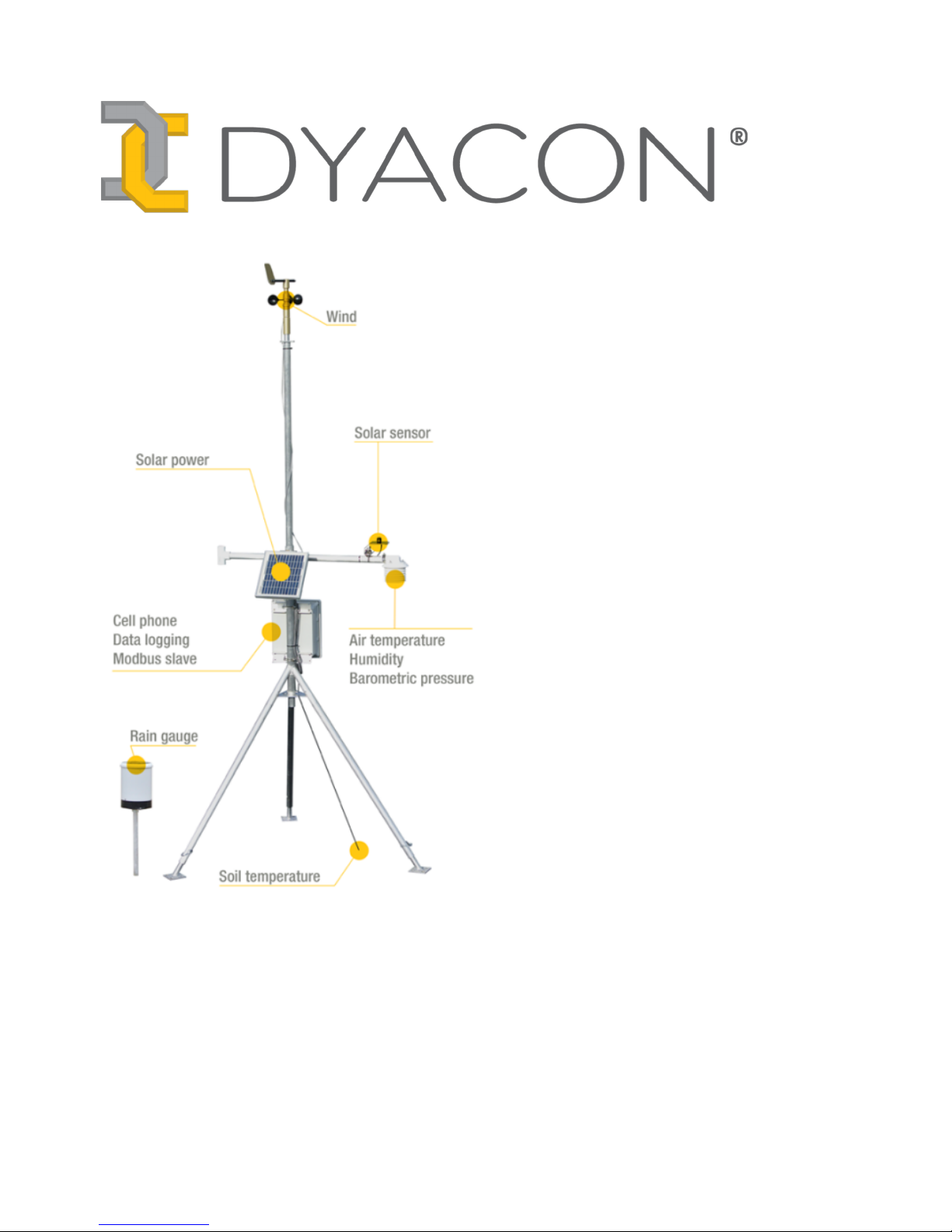
MS-100
Weather
Station
Quick-start
Guide For WiFi Stations
57-6068 Rev A
Page 2

DYACON Quick-start Guide
Intentionally left blank.
Page 2/21
Page 3

DYACON Quick-start Guide
Contents
NOTICES....................................................................................................................................................4
© Copyright 2018 Dyacon, Inc......................................................................................................4
Manufacturer..................................................................................................................................4
1.0 MS-100 INTRODUCTION..................................................................................................................5
1.1 Scope...............................................................................................................................................5
2.0 CONFIGURATION DATA FORM....................................................................................................6
3.0 MECHANICAL SETUP AND INSTALLATION.............................................................................7
3.1.1 Required Tools......................................................................................................................7
3.1.2 Mechanical Setup and Assembly Summary.........................................................................8
3.1.3 Set Vane North Position........................................................................................................9
4.0 WIRE CONNECTIONS....................................................................................................................10
4.1 Wire Stripping and Mounting.......................................................................................................10
4.2 Connection Diagram.....................................................................................................................11
5.0 CONTROLLER CONFIGURATION..............................................................................................12
5.1.1 General Settings..................................................................................................................12
5.2 Setup WiFi....................................................................................................................................12
5.2.1 Set Network Name And Password......................................................................................13
6.0 DYACONLIVE...................................................................................................................................15
6.1 Setup DyaconLive.........................................................................................................................15
6.1.1 DyaconLive User Registration............................................................................................15
6.1.2 DyaconLive Configuration.................................................................................................15
6.1.3 DyaconLive Report Interval...............................................................................................16
6.1.4 DyaconLive Test.................................................................................................................16
7.0 SITE SELECTION.............................................................................................................................17
7.1 General Principles.........................................................................................................................17
7.2 Weather Station Siting..................................................................................................................18
7.2.1 Instrumentation Considerations..........................................................................................18
7.2.2 Solar Power Considerations................................................................................................18
7.2.3 Cable Considerations..........................................................................................................18
7.2.4 Wireless (Cell Phone) Considerations................................................................................18
7.3 Airport Siting................................................................................................................................18
8.0 DOCUMENT REVISION HISTORY..............................................................................................21
Page 3/21
Page 4

Notices DYACON Quick-start Guide
Notices
© Copyright 2018 Dyacon, Inc.
All Rights Reserved
This publication is protected by copyright and all rights are reserved. Any reproduction of this
manual, in part or in full, by any means, mechanical, electronic, or otherwise, is strictly
prohibited without express written permission from Dyacon, Inc.
The information in this manual has been carefully checked and is believed to be accurate.
However, Dyacon, Inc. assumes no responsibility for any inaccuracies that may be contained in
this manual. All information is subject to change.
Trademark Acknowledgments
Dyacon® and DYACON® is a registered trademark of Dyacon, Inc, a Utah corporation.
Dyacon WSD-1TM, WSDTM, TPH-1TM, TPHTM, CM-1TM, CMTM, MS-120TM, MS-130TM, MS135TM, MS-140TM, MS-150TM and Tripod-1TM are trademarks of Dyacon, Inc.
All other trademarks are property of their respective owners.
Manufacturer
Dyacon, Inc.
1770 Research Park, Suite 168
Logan, UT 84341
US
Page 4/21
Page 5

DYACON Quick-start Guide MS-100 Introduction
1.0 MS-100 Introduction
1.1 Scope
This document is an abbreviated description of station setup and configuration. Refer to the
detailed sections in this manual or to sensor documents for further information.
The information contained in this manual is advisory only. Users are responsible for their own
safety and the installation requirements for their application.
Dyacon meteorological (met) stations are based on a control unit, or data logger, that acts as the
“brains” of the weather station. All sensors, power, and I/O devices connect to the control
module (CM).
CM-1 is a component of MS-100 series weather stations with several preconfigured version:
MS-120, MS-130, MS-135, MS-140, and MS-150. These stations differ principally by the
sensors that are pre-configured with the control module. Users may add, remove, or replace
sensors as their needs change.
This manual briefly covers site selection, station assembly, and general operation of CM-1.
Detailed information is provided in the respective product manuals.
Users should download the CM-1 Weather Station Control Module manual from Dyacon.com.
The manual is located in the documents section of the weather stations or controller page.
Videos are also available demonstrating the assembly and configuration tasks.
Page 5/21
Page 6
Configuration Data Form DYACON Quick-start Guide
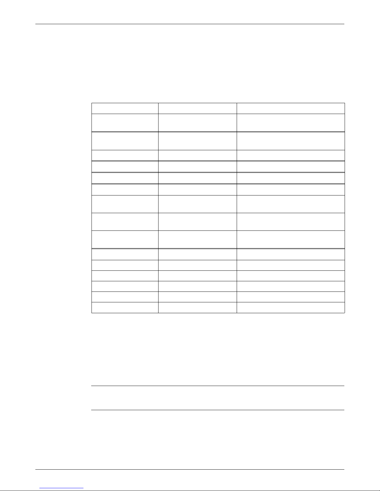
2.0 Configuration Data Form
Collecting the following information will help during configuration of the weather station
controller.
Parameter Value Notes
Station ID
User-defined text field used to identify
the station in text messages and log files.
WiFi Network Name
(SSID)
Network Password
Logging Interval 1, 2, 5, 10, 15, 20, 30, 60 min 10 min log interval = 10 months of data.
Station Altitude* meters
DyaconLive⸸ 1, 2, 5, 10, 15, 20, 30, 60 min 10 min interval recommended.
Weather Underground
ID**
Weather Underground
Password
Weather Underground
Rate
10, 15, 20, 30, 60 min
Email To**
Email From
Email User Name
Email Server
Email Password
Email Port 2525 MS-100 series does not use SSL/TLS
*Absolute air pressure is normalized to mean sea level. Altitude is required for this calculation.
Leave at zero (0) for absolute air pressure reported to Weather Underground and SMS text
messages.
⸸ DyaconLive is a webportal for Dyacon weather stations that charts measurement data and
operational parameters of the weather station. Contact Dyacon for your unique login.
** Feature implementation not required. See the respective section for more information on the
feature.
Users may find it convenient to configure the controller on the bench before placing it in the
field. To do so, merely plug in the battery and operate the unit without sensors attached.
Everything but, Set North, can be done on the bench.
Page 6/21
Page 7

DYACON Quick-start Guide Mechanical Setup and Installation
3.0 Mechanical Setup and
Installation
3.1.1 Required Tools
Installation tools depends on the mounting location. For purposes of this manual, it is assumed
that CM-1 will be used with Dyacon MS-100 weather stations and mounted on Dyacon
Tripod-1.
Control Module
8 mm (5/16 inch) socket for band clamps
Phillips #2 driver for Control Module cover
0.10” to 0.13” (2.5 mm to 3.5 mm) wide slotted driver for screw terminals
Tripod
7 mm open-end wrench for guy cable clips
Hammer for stakes or tools appropriate for other mounting method, as required.
WSD-1
Phillips #2 driver to attach wind vane and pole set screw
TPH-1
8 mm (5/16 inch) socket for band clamps
Crossover
8 mm (5/16 inch) socket for band clamps
Solar Panel Bracket
8 mm (5/16 inch) socket for band clamps
Rain Gauge
8 mm (5/16 inch) socket for band clamps on bracket
4 mm (5/32 inch) hex wrench (included with gauge) to remove rain gauge top.
13 mm (9/16 inch) open-end wrench or adjustable open-end wrench for leveling screws.
Other
Wire cutters for electrical cable prep and cable ties
Wire stripper for 24 AWG to 22 AWG wire
Page 7/21
Page 8
Mechanical Setup and Installation DYACON Quick-start Guide
3.1.2 Mechanical Setup and Assembly Summary
The following is a summarized setup procedure. Videos are available at Dyacon.com
1. Erect Dyacon Tripod-1 with only one mast segment in place.
2. Loop guy cables over top of mast.
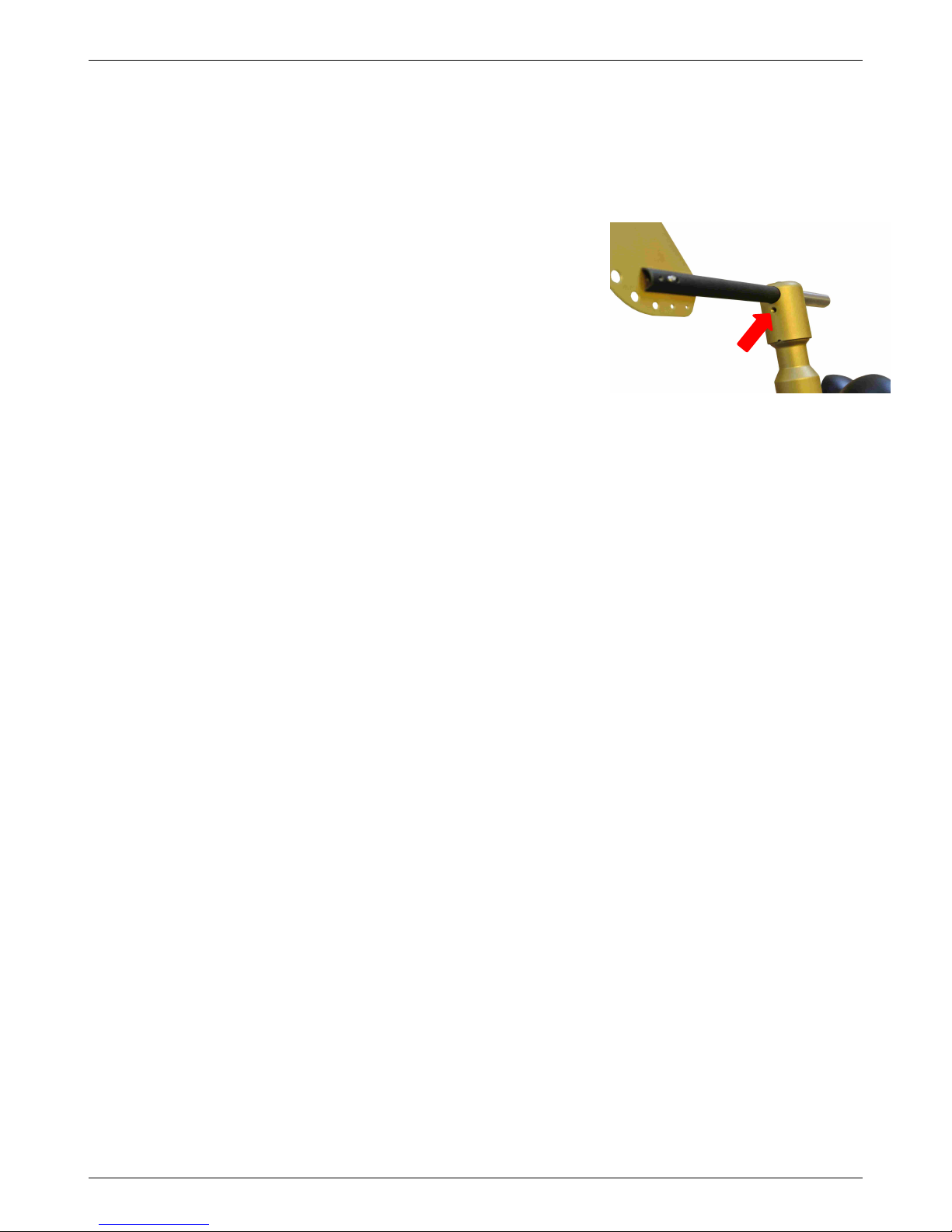
3. Assemble WSD-1 vane.
Remove the Vane axis screw.
Insert the vane and counter weight with the end
pointing away from the set screw hole.
Insert and tighten the axis screw.
4. Attach WSD-1 to top of mast.
Orientation does not matter. The North alignment
position will be set electronically, see step 20.
5. Attach crossover to the top of the center mounting pipe (tripod hub) and secure with two
band clamps.
The solar module mounting bracket can be secured on the opposite side of the pipe with the
same band clamps as used for the crossover. The solar module bracket should be positioned
toward the south, if in the northern hemisphere or toward the north if in the southern
hemisphere.
6. Attach CM-1 enclosure below the crossover using two band clamps.
7. Insert pipe into horizontal fitting of the crossover and tighten with two band clamps.
8. Fit TPH-1 onto end of horizontal pipe and tighten band clamp.
9. Attach solar sensor (pyranometer) to bracket. (Optional sensor.) The cable leaving the solar
sensor should be directed to the north.
10. Attach solar sensor bracket to TPH-1 by removing two wing nuts.
11. Seat solar power module onto mounting bracket.
12. Place soil moisture sensor and soil temperature sensor into ground and desired depth.
13. Bury rain gauge pipe.
14. Mount rain gauge to top of pipe.
15. Remove the rain gauge top and remove the rubber band securing the tipping
mechanism.
16. Open the control module by loosening the two front cover screws.
17. Feed each sensor cable through cable glands at the bottom of the enclosure and attach to
respective terminals.
18. Plug in the battery connector to the control module connecter. (For cable-powered systems,
attach 7 VDC to 24 VDC to the Battery connector.)
19. Attached the solar module to the solar power input.
20. Set North position on the wind vane before raising mast. (See instructions in 3.1.3.)
21. Attach cable ties to WSD-1 while raising the tripod mast to full height.
22. Bundle excess cable on the outside of the enclosure.
23. Secure cables with cable ties so that they route adjacent to the tripod structure.
24. Configure control module as required. (See the following section.)
Page 8/21
Image 3.1: Vane Fin On Same Side as Set Screw.
Page 9
DYACON Quick-start Guide Mechanical Setup and Installation
3.1.3 Set Vane North Position
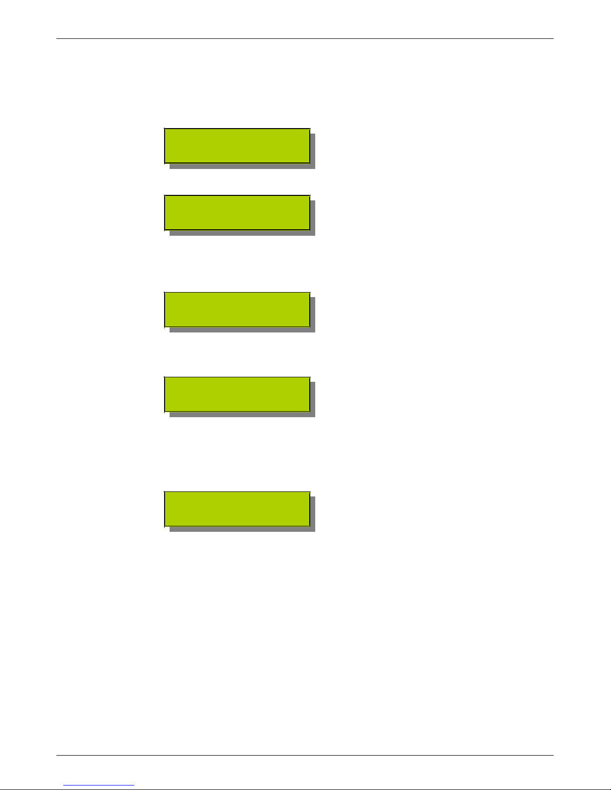
Press Select will enable Setup mode.
Press ▼ (Down) until Wind Dir is seen.
>Setup Wind Dir
Press Select to enter the Set New North configuration.
>Set New North
Manually hold or tape the vane in the desired position (magnetic or grid north, depending the
application.
Press Select to set the position as 0 degrees.
North Set
Continue holding the vane in the north position to validate the setting.
The display will show “North Set” momentarily, then return to the configuration page.
>Set New North
Clear Setting
Pressing Cancel twice will exit Setup mode and return to Acquisition mode.
By paging down one position, users will see the direction. The wind direction should show a
value near 0 or 360 deg.
Acquisition page after setting north.
1.2 m/s @ 0.1 deg
Gust: 0.0 st: 0
Page 9/21
Page 10
Wire Connections DYACON Quick-start Guide
4.0 Wire Connections
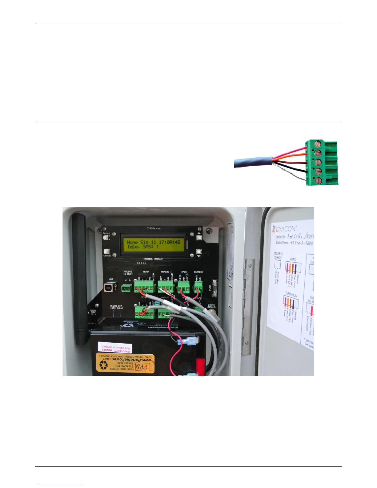
CM-1 utilizes pluggable terminal blocks. These connectors may be unplugged from the circuit
board and wired in a convenient position using a slotted screw driver.
4.1 Wire Stripping and Mounting
Wires should be stripped to about 7 mm (0.25 inch).
Care should be taken to ensure that there are no loose
strands when inserting wires.
Screw terminals should be firmly tightened and
checked as part of a routine maintenance program.
Page 10/21
Image 4.1: Wired for Dyacon Control Module
Image 4.2: Typical Installation
Page 11
DYACON Quick-start Guide Wire Connections
4.2 Connection Diagram
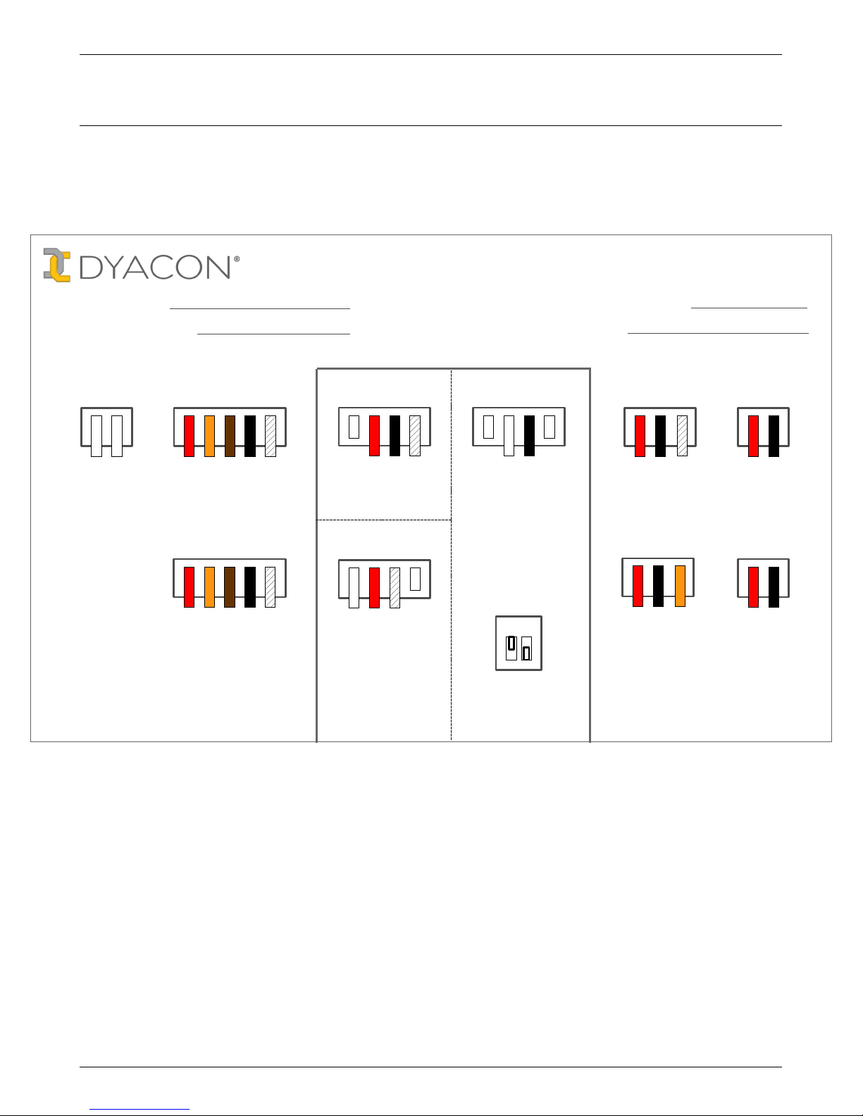
A diagram similar to the following is attached to the inside of the CM-1 enclosure. The diagram
shows common sensors that may be supplied as part of MS-100 series weather stations. This
diagram may be reproduced should the version in the station become damaged.
Page 11/21
MS-100 Series Met Station Connections
TSSP-1
Temp Probe
L
e
a
d
2
L
e
a
d
1
N
e
g
a
t
i
v
e
PSP-110
Solar Sensor
P
o
s
i
t
i
v
e
S
h
i
e
l
d
ANALOG PORTS
G
n
d
V
+
BATTERY
(DC Power)
L
e
a
d
2
L
e
a
d
1
RAIN
S
h
i
e
l
d
G
n
d
V
+
SOLAR
PANEL
Aspiration
G
n
d
1
2
V
o
u
t
FAN
S
e
n
s
e
D
a
t
a
(
A
+
)
MODBUS
TO HOST
D
a
t
a
(
B
)
Station Phone:
Station ID:
S
h
i
e
l
d
D
a
t
a
(
A
+
)
V
I
n
p
u
t
TEMP/HUM
P
w
r
G
n
d
D
a
t
a
(
B
)
S
h
i
e
l
d
D
a
t
a
(
A
+
)
V
I
n
p
u
t
P
w
r
G
n
d
D
a
t
a
(
B
)
WIND
S
h
i
e
l
d
D
a
t
a
(
A
+
)
V
I
n
p
u
t
P
w
r
G
n
d
D
a
t
a
(
B
)
G
n
d
(
B
a
r
e
)
S
e
n
s
o
r
O
u
t
E
x
c
i
t
a
t
i
o
n
SMEC-5
Soil Moisture
ON
OFF
A
n
a
l
o
g
2
A
n
a
l
o
g
1
Temp Probe
Switches
1 2
Dyacon Support
435-753-1002
dyacon.com
[email protected]
Set ON for TSSP-1
Set switch OFF for
other sensors.
Elevation (m):
GPS:
Page 12
Controller Configuration DYACON Quick-start Guide
5.0 Controller Configuration
5.1.1 General Settings
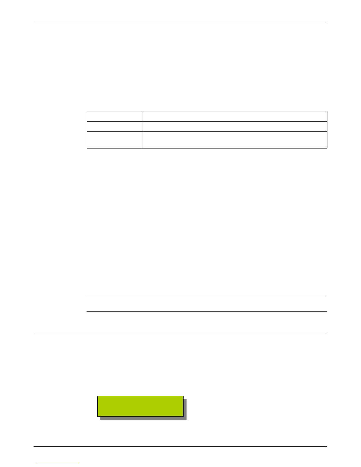
Controller configuration may be done using one of three different methods. The CM-1 manual
contains detailed instructions for each.
CM Utility A Windows application. The PC is connected to the USB port on CM-1
Local User Interface The controller contains an LCD and four buttons.
SMS SMS text message command may be sent from a cell phone or online
services such as Google Voice.
CM Utility is the easiest and most intuitive method. The program may be downloaded from the
weather station product page.
1. Set the station ID or name that will be transmitted in text messages and log files.
2. Assign analog port functions to pre-configured sensor options.
3. Set measurement units for wind, temperature, and pressure.
4. Set the north position of wind vane before raising the mast.
5. Set the station elevation in meters.
6. Enable logging and set the interval.
7. Set WeatherUnderground ID and password.
8. Enable WeatherUnderground.
9. Set email parameters as required.
10. Enable automatic email of log file under log settings.
All of the above settings, except North Setting, may be done through SMS text messages, if a
cell phone module is installed and provisioned.
5.2 Setup WiFi
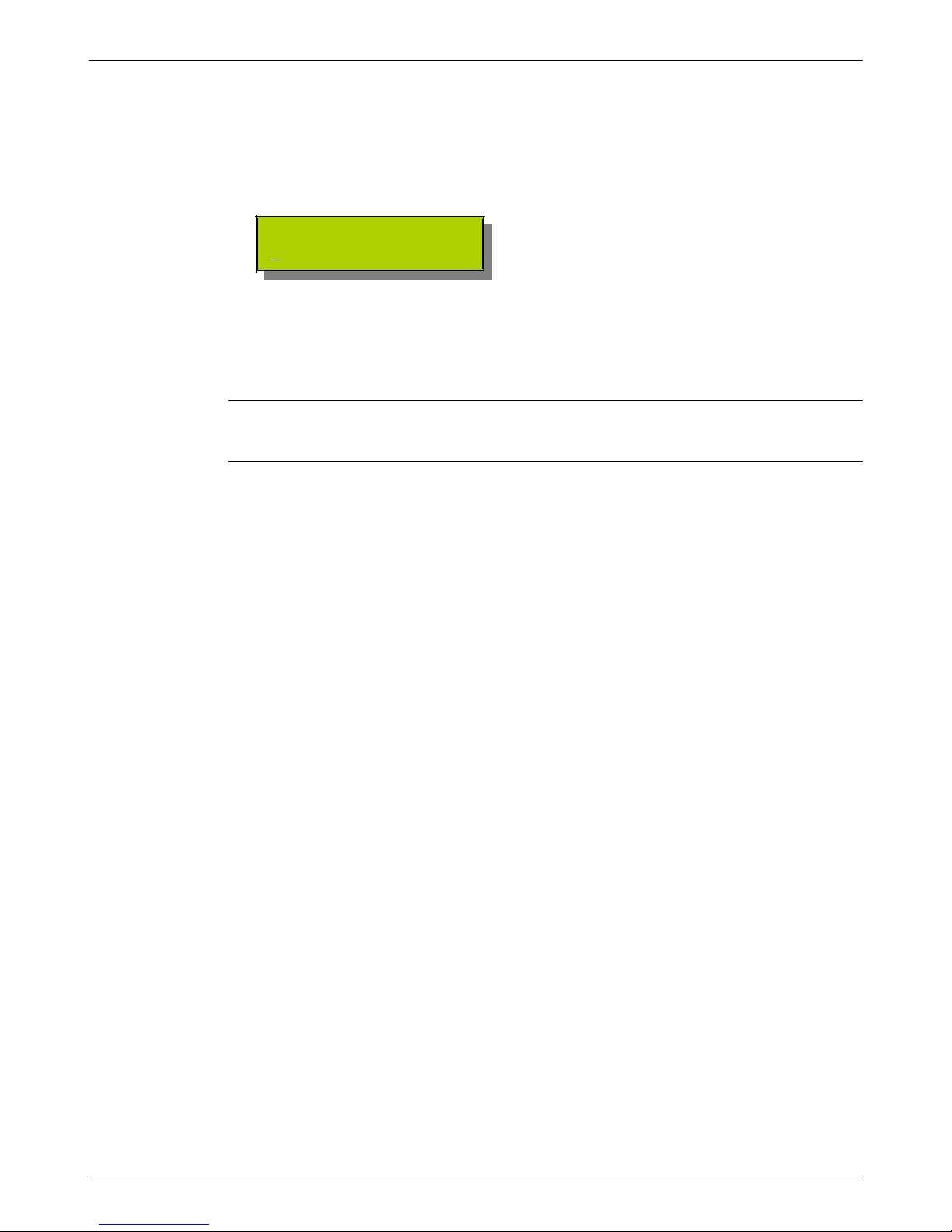
WiFi may be configured using the LCD or the Windows program, Dyacon Control Module
Utility. The LCD configuration is shown below.
The WiFi network name (SSID) and password for the access point must be set in order for the
controller to send data to DyaconLive.
>WiFi Settings
Page 12/21
Page 13
DYACON Quick-start Guide Controller Configuration
5.2.1 Set Network Name And Password
The Access Point Name, SSID, or Network Name is broadcast by the WiFi access point. This,
and the corresponding password, are available from the network administrator.
Dyacon weather stations use the 2.5 MHz WiFi band.
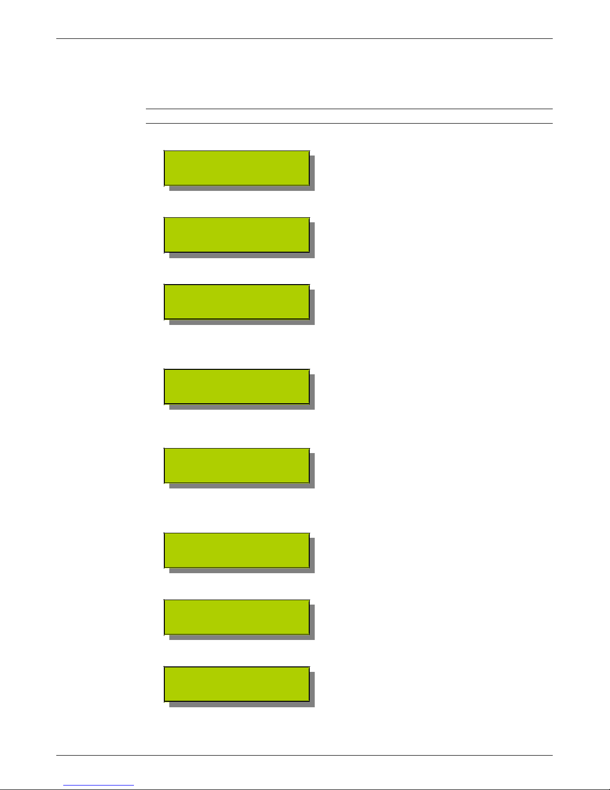
Press Select to enter the cell phone settings.
>AP:
Pass:
The weather station controller will immediately begin searching for available networks.
Searching...
A list will be shown on the LCD.
>MyNetwork
SomeOtherNetwork
Use the ▲ (Up) and ▼ (Down) buttons to find your network.
Press Select on the desired network.
>AP: MyNetwork
Pass:
Use the ▲ (Up) and ▼ (Down) buttons to advance to the password setting and then press
Select.
WiFi Password
▓
Use the ▲ (Up) and ▼ (Down) buttons to scroll to the characters of the password.
Press Select when the correct character is shown.
WiFi Password
Password123▓
Press Select again when all characters have been entered.
>AP: MyNetwork
Pass: ***********
Press Cancel to exit setup mode and a second time to return to Acquisition Mode.
>WiFi UTC 00:29:23
Signal: -37 dBm
The home screen will show the Signal strength of the WiFi (updated every 10 s) and the time in
UTC (also knows as Zulu or GMT).
Page 13/21
Page 14
Controller Configuration DYACON Quick-start Guide
Manual WiFi Setup
For networks that do not broadcast SSID, it may be necessary to setup the WiFi name manually.
Follow the same process as above. Following the search, use the ▲ (Up) and ▼ (Down) buttons
to scroll down to Manual Entry.
Press Select to enter the WiFi network name.
Enter Access Point
MyNetw▓
Use the ▲ (Up) and ▼ (Down) buttons to find the characters and Select to advance to the next
one. Press Select again when the name is complete.
Continue with the process cescribed above to enter the network password.
If the SSID is not broadcast automatically, the signal strength will update only when the weather
station controller is reset. This may affect the ability to assess the network connection and align
any directional antennas.
Page 14/21
Page 15
DYACON Quick-start Guide DyaconLive
6.0 DyaconLive
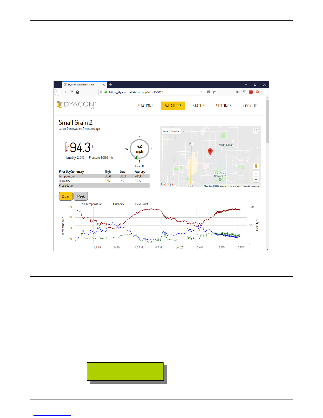
Data from WiFi weather stations is transmitted to DyaconLive (dyacon.net).
6.1 Setup DyaconLive
DyaconLive (dyacon.net) is a weather station web portal designed and programmed by Dyacon
staff.
6.1.1 DyaconLive User Registration
DyaconLive is access controlled. Users must contact Dyacon to create an admin user account.
6.1.2 DyaconLive Configuration
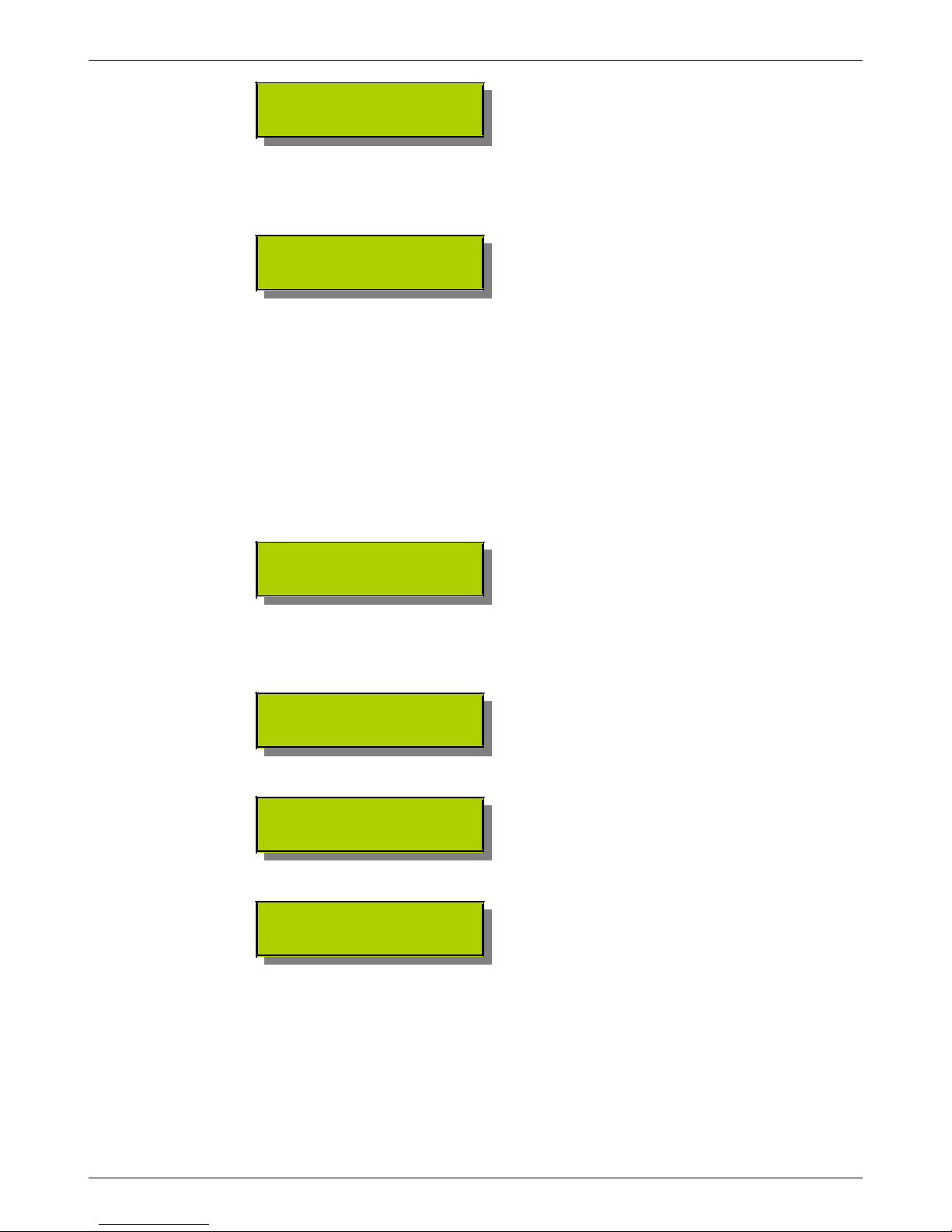
DyaconLive can be enabled or disable and the update rate specified.
>Setup DyaconLive
Rate: Off
Pressing Select will enable configuration of DyaconLive settings.
Page 15/21
Page 16
DyaconLive DYACON Quick-start Guide
>Update Rate: Off
Test Connection
6.1.3 DyaconLive Report Interval
Press Select to edit the on/off status and set reporting interval.
Set Update Rate
Off
Use the ▲ (Up) and ▼ (Down) buttons to turn the feature on at the desired interval, 1, min, 2
min, 5 min, 10 min, 15 min, 20 min, 30 min, or 1 hr. Longer intervals may be helpful at reducing
system power and data usage.
A 10 min interval is recommended.
Press Select to save.
6.1.4 DyaconLive Test
To initiate a test of the DyaconLive connection.
Use the ▲ (Up) and ▼ (Down) buttons to select the Test Connection option.
Update Rate: Off
>Test Connection
Press Select.
The display will exit Setup mode and return to the home screen and show the progress of the test
packet transmission.
WiFi UTC 17:33:51
Dyacon Connecting
WiFi UTC 17:33:51
Dyacon Sending
WiFi UTC 17:33:52
Dyacon Complete
An error message may show if the test is unsuccessful. Contact Dyacon if the error is not
obvious.
Page 16/21
Page 17

DYACON Quick-start Guide Site Selection
7.0 Site Selection
7.1 General Principles
If you are following this guide sequentially, you have probably placed your weather station in
the wrong location. However, the real geeks will read this before staking their tripod to the
ground and can now pat themselves on the back.
Weather station placement is dependent upon the role it will play. A weather station intended to
monitor an outdoor storage facility will be placed differently than one intended for
meteorological, aviation, or agricultural purposes.
Wind
While the World Meteorological Organization (WMO) specifies a height of 10 m, many
installations do not require this height.
Shrubs, trees, terrain, and structures will cause turbulent conditions that will affect the measured
wind speed and direction. Depending on the application, it may or may not be desirable to
measure this condition.
The wind sensor should be positioned at a height above the ground that captures the wind
exposure of the critical asset. For example, agricultural growers may chose to place the wind
sensor at a height that represents the crop exposure.
Aviation applications have unique requirements, see the Airport Siting section.
Air Temperature
Installers should recognize that radiant or reflected energy sources will affect the temperature
sensor. Buildings, roofs, ground surface, vegetation, and water ways will affect the measured
temperature.
The WMO standard for temperature and humidity measurements is 2 m above the ground
surface.
Similar to wind, the temperature sensor should be placed to capture the conditions of the desired
asset.
Locations that must measure still air while exposed to the sun or other radiating sources may
benefit from Dyacon's aspirator option. The aspirator is available as an upgrade kit.
Soil and Liquid
Soil temperature and soil moisture probes are placed at the desired depth for the purpose.
Measurements of seed germination characteristics would require different depths than irrigation
monitoring or seepage detection.
Dyacon's stainless steel temperature probe may be used for liquid submersion and surface
contact applications, such as evaporation ponds, watering troughs, and surface temperature.
Insolation
Solar sensors are typically positioned to capture unimpeded sunlight. This type of placement
may be appropriate for modeling solar power generation. However, other application may
require sensor placement within a shaded area, such as within the canopy of a crop.
Page 17/21
Page 18

Site Selection DYACON Quick-start Guide
7.2 Weather Station Siting
7.2.1 Instrumentation Considerations
The following are general guidelines.
Wind sensor height: 10 m
Temperature and humidity sensor height: 2 m
Distance from nearby structures: Distance to structure >= 10 times the structure height
Roof-top mounting is not recommended due to significant temperature and wind effects from the
structure and reflected heat.
7.2.2 Solar Power Considerations
MS-100 stations may be powered by 10 W solar panels. This input capacity is sufficient where
full sun exposure is available during the day. Installations that have high wireless demand and
are shaded for part of the day may require a second solar panel.
7.2.3 Cable Considerations
CM-1 may be used with a cabled connection. The differential signal (RS-485) used by the
Modbus port allows for very long cable runs. Low-capacitance cable, such as CAT-5 can be
used in excess of 1000 ft (900 m). The Modbus baud rate may be lowered to achieve even
longer cable lengths or overcome cable characteristics.
7.2.4 Wireless (Cell Phone) Considerations
MS-130, MS-140, and MS-150 weather stations have an embedded cellular phone transceiver.
Ideally, the cell phone tower must be in direct line-of-sight of the weather station.
The control module contains an antenna with better gain characteristics that the typical handset.
The station may operate reliably even in locations where handsets may not have an adequate
signal.
The control module home screen shows the cell phone signal strength. A signal level above 5 is
desirable.
The mounting mast and other obstructions may reduce the signal strength in some conditions. If
the signal strength is low or varies by more that 5, the control module may be rotated on the
mounting mast for maximum signal strength.
If this technique is inadequate, contact Dyacon for further instructions.
7.3 Airport Siting
Dyacon weather stations are for ADVISORY INFORMATION ONLY, they are not FAA
certified as ASOS or AWOS systems.
The information give here is for installer consideration only. Installers should consult
appropriate experts and authorities as necessary.
Page 18/21
Page 19
DYACON Quick-start Guide Site Selection
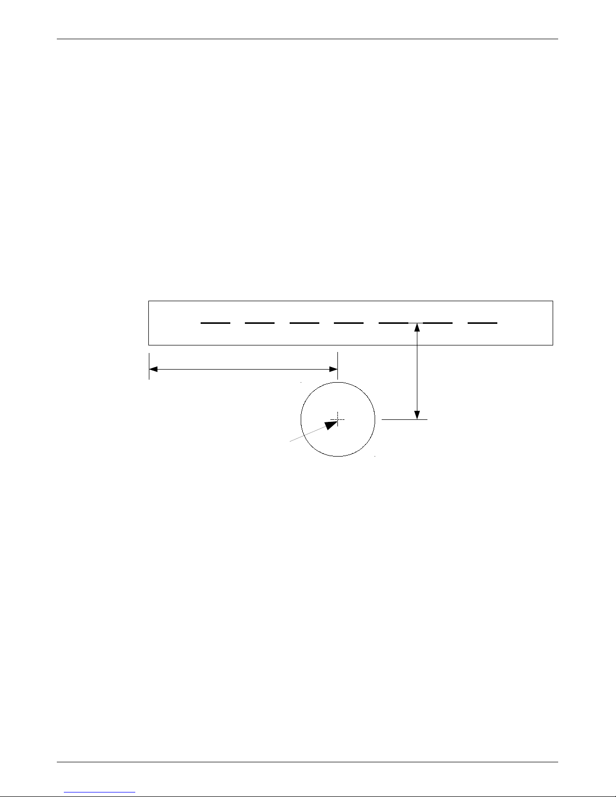
Ideally, the weather station wind sensor would be mounted on a 30 ft tower, positioned within a
clear circle of 1000 ft in diameter the center of which is offset from the center of the field by 500
ft to 1000 ft. (See the diagram below.)
Rural and private airports may not have sufficient area to meet this ideal, especially if a 30 ft
rigid tower is used. For small aircraft (<12,500 lbs), a setback from the centerline of the runway
of 125 ft plus 7 times the height of the wind sensor structure should be considered a minimum.
If the Dyacon 7-segment tripod is used, the weather station would be placed at mid-field at least
244 feet from the runway centerline. (7 x 17 ft + 125 ft = 244)
Airport owners should use their best judgment of prevailing wind directions, nearby
obstructions, and surface characteristics to position the station for best indication of surface
conditions while observing setback guidelines.
The Dyacon tripod would be considered “frangible” in that it would be knocked over if struck
by an aircraft.
Visual or Non-precision Runway Diagram
Ideal weather station placement. (FAA Order 6560.20B, Siting Criteria For Automated Weather
Observing Systems(AWOS), 7/20/98. Also, see ICAO Doc 9837 AN/454, Fig. 3-1)
Manual on Automatic Meteorological Observing Systems at Aerodromes (ICAO Doc 9837 AN/
454) states:
3.6.1 Measurements cannot of course be taken on the runway, and it is important to follow
the obstacle clearance rules in Annex 14 — Aerodromes, Volume I, Chapter 8, and the
Airport Services Manual (Doc 9137), Part 6. The minimum distance of a 10-m frangible
mast in relation to the runway centre line is 90 m. The mast must be placed in this zone only
if absolutely necessary; in most circumstances, a 10-m mast should be at least 220 m from
the runway centre line. These criteria are shown in more detail in Figure 3-1.
The Dyacon tripod is less than than the 10-m mast referenced above and may be placed closer to
the runway.
Page 19/21
2
3
5
500 ft to
1000 ft
1000 ft to 3000 ft
Weather station inside of
circular clearing of 1000
ft diameter.
Page 20
Site Selection DYACON Quick-start Guide
Non-airport Heliport Siting
The location of the station should be outside of hover and taxi operations. For medium-weight
helicopters, 100 ft separation from the landing site may be adequate to avoid affects to the
weather sensors from rotor downwash and dust.
Ideal weather station placement. (FAA Order 6560.20B, Siting Criteria For Automated Weather
Observing Systems(AWOS), 7/20/98)
Page 20/21
H
Weather Station
100 ft to
700 ft
Page 21
DYACON Quick-start Guide Document Revision History
8.0 Document Revision History
Rev Description Author Date
A Initial release. E. Bodrero 20 Jul 2018
Page 21/21
 Loading...