

Dyaco YR001 User Manual

CW800
Rower
OWNER’S MANUAL
Please carefully read this entire manual befor e operating your new rower.
Thank you for purchasing our product, please save these instructions. Please do
not perform or attempt any customizing, adjustments, repair or maintenance that is
not described in this manual, if you experience any difficulty, please contact our
website.
NOTE:
Article number: CW800
Use: Studio use
Max. user’s weight.: 150kg
1

TABLE OF CONTENTS
IMPORTANT SAFETY INSTRUCTIONS…………………………………………..……2
IMPORTANT ELECTRICAL INSTRUCTIONS………………………………………….3
IMPORTANT OPERATION INSTRUCTIONS……………………………………..…….4
ASSEMBLY INSTRUCTIONS……………………………………………………….…….5
CONSOLE OPERATION………………………………………………………………….10
OPERATING INSTRUCTION…………………………………………………………….13
USING HEART RATE TRANSMITTER………………………………………………….20
WIRELESS HANDLE PAIRING…………………………………………………….…….22
HANDLE BATTERY CHANING INSTRUCTIONS………………………..…………….23
GENERAL MAINTENANCE…………………………………………………...………….23
Exploded View Diagram……………………………………………………..…….…….. 24
Parts List…………………………………………………………………………..………. 25
Thank you for purchasing our product, please save these instructions. Please do not perform
or attempt any customizing, adjustments , repair or maintena nce that is n ot desc ribed in th is
manual.
CW800-YR001_1604A
2

Important Safety Instructions
WARNING
When using an electrical appliance, basic precautions should always be followed, including the
following:
Read all instructions before using this appliance.
DANGER - To reduce the risk of electric shock:
Always unplug this applicance from the electrical outlet immediately after using and before
cleaning.
WARNING - To reduce the risk of burns, fire, electric shock, or injury to persons, install the Rower
on a flat level surface with access t o a 110- volt, 15-amp grounded outlet with only th e Row er
plugged into the circuit.
DO NOT USE AN EXTENSION CORD UNLESS IT IS A 14AWG OR BETTER, WITH ONLY ONE
OUTLET ON THE END:
Do not operate Rower on deeply padded, plush or shag carpet. Damage to both carpet and
Rower may result.
Keep children away from the Rower. There are obvious pinch points and other caution areas
that can cause harm.
Keep hands away from all moving parts.
Never operate the Rower if it has a da maged co rd or plug . If the Rower is no t working properly,
call your dealer.
Keep the cord awa y fro m heat e d surf ac es.
Do not operate where aerosol spray products are being used or where oxygen is being
administered. Sparks from the motor may ignite a highly gaseous environment.
Never drop or insert any object into any openings.
Do not use outdoors.
To disconnect, turn all controls to the off position, then remove the plug from the outlet.
Do not attempt to use your Rower for any purpose other than for the purpose it is intended.
Use of a chest strap transmitter (sold separately) is an accurate method of hear t ra te analysis.
Various factors, including the user’s movement, may affect the accuracy of hear t rate
readings.
Wear proper shoes. High heels, dress shoes, sandals or bare feet are not suitable for use on
your Rower. Quality athletic shoes are recommended to avoid leg fatigue.
CAUTION:
To assure continued FCC compliance:
1. Any changes or modifications not expressly approved by the grantee of this device could void
the user's authority to operate the equipment.
2. This equipment complies with FCC radiation exposure limits set forth for an uncontrolled
environment. This equipment should be installed and operated with minimum distance of 20 cm
between the radiator and your body.
SAVE THESE INSTRUCTION S - THINK SAFETY!
3

Important Electrical Instructions
WARNING
NEVER remove any cover without first disconnecting AC power. If voltage varies by ten percent
(10%) or more, the performance of your Rower may be affected. Such conditions are not covered
under your warranty. If you suspect the voltage is low, contact your local power company or a
licensed electrician for proper testing.
NEVER expose this Rower to rain or moisture. This product is NOT designed for use outdoors,
near a pool or spa, or in any other high humidity environment. The operating temperature
specification is 40 to 120 degrees Fahrenheit, and humidity is 95% non-condensing (no water
drops forming o n surfaces).
Circuit Breakers: Some circuit breakers used in homes are not rated for high inrush currents that
can occur when a Rower is first turned on or even during use. If your Rower is tripping the house
circuit breaker (even though it is the proper current rating) but the circuit breaker on the Rower
itself does not trip, you will need to replace the home breaker with a high inrush type. This is not a
warranty defect. This is a condition we as a man ufact ure ha ve no abilit y to con trol. This part is
available through most electrical supply stores. Examples: Grainger part # 1D237, or available
online at www.squared.com part #QO120HM.The electr ic al o utlet us ed should h av e a ded icat ed
15 amp circuit breaker.
Grounding Instructions
This product must be grounded. If the Rower should malfunction or breakdown, grounding
provides a path of least resist ance for electric current, reducing the risk of electric shock. This
product is equipped with a cord having an equipment- grounding plug. The plug must be plugged
into an appropriate outlet that i s prope rly installed and groun ded i n acco rdan ce with all l ocal cod es
and ordinances.
DANGER - Improper connection of the equipment- grounding conductor can result in a risk of
electric shock. Check with a qualified electrician or serviceman if you are in doubt as to whether
the product is properly grounded. Do not modify the plug provided with the product if it will not fit
the outlet; have a proper outlet installed by a qualified electrician.
This product is for use on a nominal 110-volt/15 amp dedicated circuit, and has a grounding plug
that looks like the plug illustrated below. A temporary adapter that looks like the adapter illustrated
below may be used to connec t t his p lu g to a 2- pole rece pt acle as s hown below if a pr oper ly
grounded outlet is not available. The temporary adapter should be used only until a properly
grounded outlet, (shown below) can be installed by a qualified electrician. The green colored rigid
ear-lug, or the like, extending from the adapter, must be connected to a permanent ground such as
a properly grounded outlet box cover. Whenever the adapter is used, it must be held in place by a
metal screw.
4

Important Operation Instructions
NEVER operate this Rower without reading and completely understanding the results of any
operational change you request from the computer.
Understand that changes in resistance do not occur immediately. Set your desired resistance
level on the computer c onso l e and release the adjustment key. The computer will o bey th e
command gradually.
Use caution while participating in other activities while pedaling on your Rower ; such as
watching television, reading, etc.
These distractions may cause you t o lose balance which may result in serious injury.
Do not use excessive pres sure on c onso le c ontro l keys. They are precision set to function
properly with little finger pressure.
5
Assembly Instructions
PRE-ASSEMBLY
1. Using a razor knife (Box Cutter), cut the banding straps that wrap around the carton. Reach
under the bottom edge of the carton and pull it away from the cardboard underneath,
separating the staples that join the two together. Lift the box over the unit and unpack.
2. Carefully remove all parts from carton and inspect for any damage or missing parts. If damaged
parts are found, or parts are missing, contact your dealer immediately.
3. Locate the hardware package. The hardware is separated into four steps. Remove the tools
first. Remove the hardware for each step as needed to avoid confusion. The numbers in the
instructions that are in parenthesis (#) are the item number from the assembly drawing for
reference.
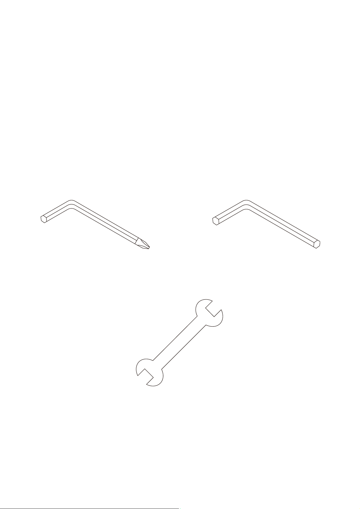
Assembly Tools
#127. Combination M5 Allen Wrench
& Phillips Head Screw Driver
(1 pc)
#126. L Allen Wrench
(1 pc)
#128. 13/14m/m Wrench
(1 pc)
6
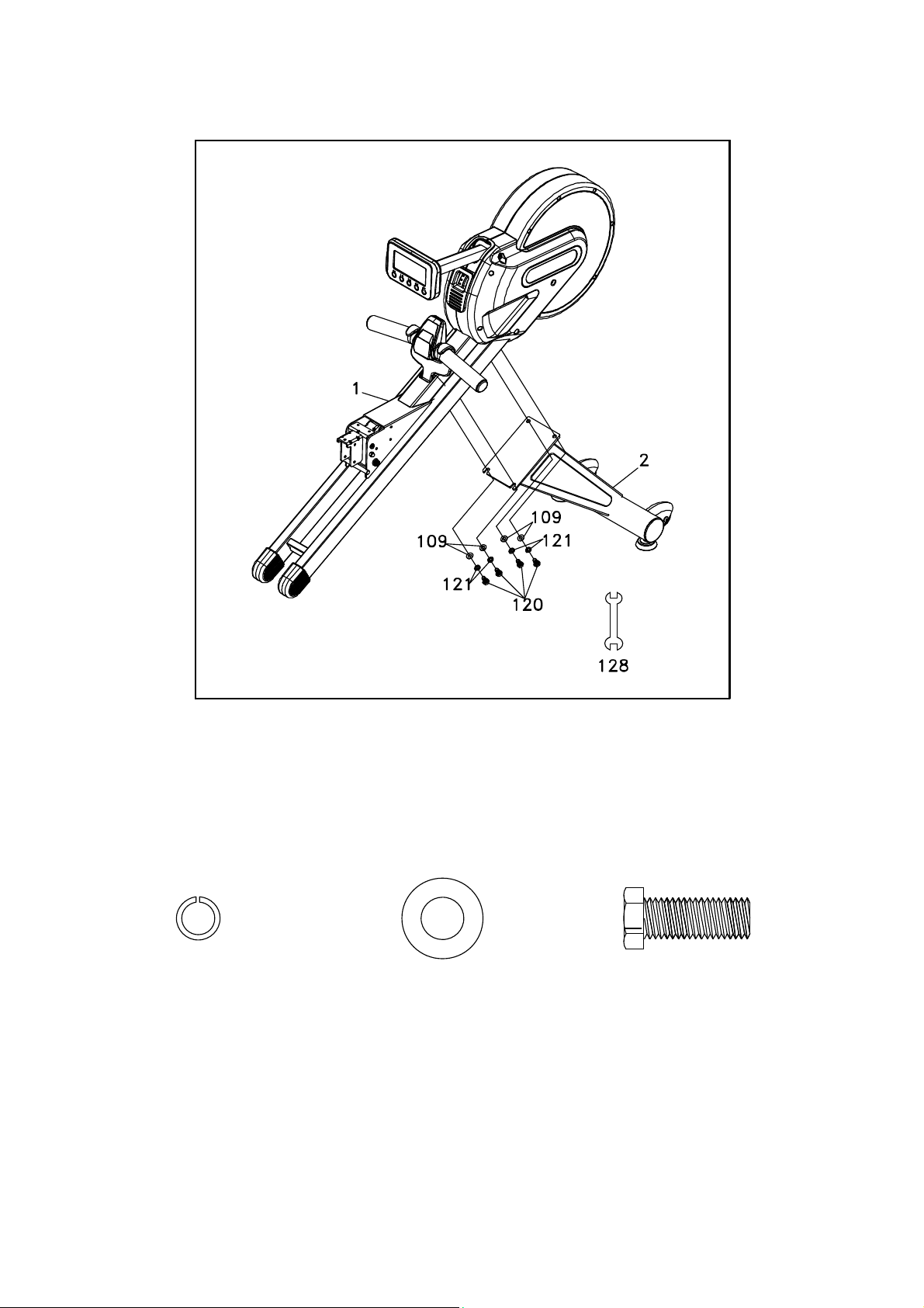
STEP 1
1. Gather HARDWARE FOR STEP 1.
2. Use the WRENCH (128) to tighten 4 HEX HEAD BOLTS (120) together with 4 SPRING
WASHERS (121) and 4 FLAT WASHERS (109) to secure the MAIN FRAME (1) and FRONT
STABI LIZER (2) together.
HARDWARE
#121. 10 × 2T
Spring Washer
(4 pcs)
#109. 3/8" × 19 × 1.5T
Flat Washer
(4 pcs)
#120. 3/8" × 3/4"
Hex Head Bolt
(4 pcs)
7
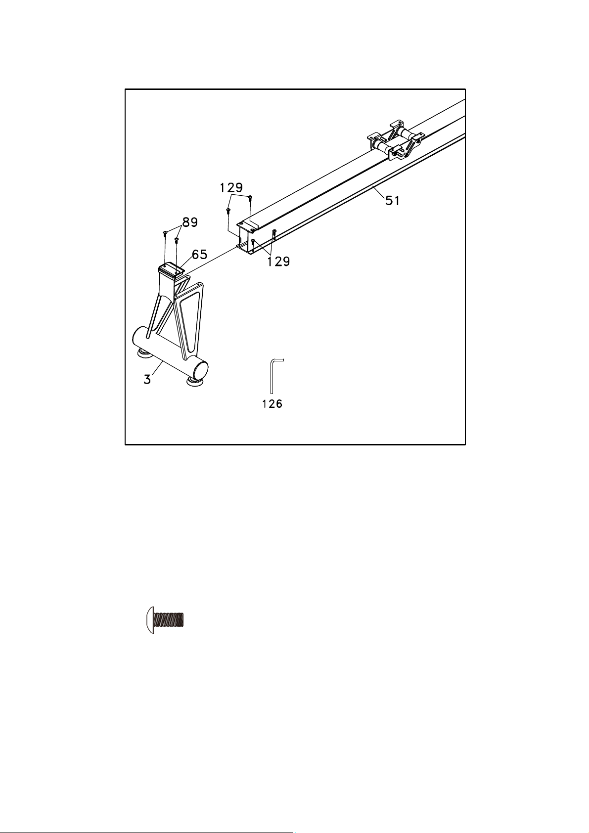
STEP 2
1. Gather HARDWARE FOR STEP 2.
2. Use ALLEN WRENCH (126) to remove 2 BUTTON HEAD SOCKET BOLTS (89) on
ALUMINUM TRACK (51), then attach SEAT STOP COVER (65) to REAR STABILIZER (3) and
install at rear end of the ALUMINUM TRACK (51). Use ALLEN WRENCH (126) to tighten 4
BUTTON HEAD SOCKET BOLTS (129) and 2 BUTTON HEAD SOCKET BOLTS (89) onto the
Aluminum Track (51).
HARDWARE
#129. M6 × 10m/m
Button Head Socket Bolt
(4pcs)
8
 Loading...