

Dyaco XE515SD-YE005 Service Manual
XE515SD-YE005
Elliptical
Service Manual

-----------------------------------------Table of Content-----------------------------------------------
1. Elliptical Outlines
2. Electronic Parts
2.1 Upper Controllers
2.2 Lower Controller and Driver
3. Electrical Configurations
4. Elliptical Operation
5. Elliptical Unit Block Diagrams
6. Elliptical Basic Connections and Wiring
6.1 Display Board Wire Connections
6.2 Display Board PCB Component Locations
6.3 The Console Interface Board Wire Connections
6.4 Amplifier Board Wire Connections
6.5 Driver Board Wire Connections
6.6 Driver Board PCB Component Locations
6.7 Driver Board LED Indicator Locations
6.8 Controller Indicator LED Debugging
6.9 Driver Board Function
6.10 Tension Motor Connector Definition Function
7. Product Safety Instructions
7.1 Important Safety Instructions
7.2 Important Electrical Instructions
7.3 Important Grounding Instructions
8. Elliptical Error Messages and Troubleshooting for electronic Issues
8.1 Error Message: E1
8.2 Error Message: E2
8.3 Error Message: INCLINE E3
8.4 Circuit Diagram
8.5 Calibration Procedure
8.6 Fuse Replacement
8.7 Troubleshooting Procedure Matrix for Electronic Issues
9. Troubleshooting
9.1 Console Problem
9.2 Side Case & Round Disk Problem
9.3 Flywheel Problem
9.4 Poly-V Belt Problem
9.5 Swing Arm Problem
9.6 Connecting Arm and Slide Wheel Problem
9.7 Controller & Incline Motor Problem

SSeerrvviiccee MMaannuuaal
l
9.8 Tension Motor Problem
10. Q & A
10.1 Noise
10.2 Slip Problem
10.3 Shaking Problem
10.4 Smooth Problem
11. Disassembling and Assembling of Parts
11.1 Console Replacement
11.2 Swing Arm Replacement
11.3 Connecting Arm Replacement
11.4 Pedal Arm Replacement
11.5 Console Mast Replacement
11.6 Side Case Replacement
11.7 Cross Bar Replacement
11.8 Idler Wheel Replacement
11.9 Flywheel & Poly-V Belt Replacement
11.10 Rear Frame Replacement
11.11 Rail & Incline Motor Replacement

1. Elliptical Outlines
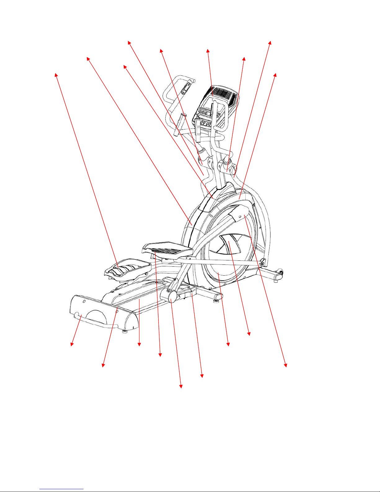
(1) Plastic parts
Front & back handlebar cover (R)
Rear cover(1)
Rear cover(2)
Middle cover
Pedal(R)
Slide wheel cover(R)
Bottom cover
Pedal arm cover(R)
Round disk cover
Round disk
Right side case
Swing Arm Bushing
Console Swing Arm Bushing
Left side case
Console mast cover
Pedal(L)
Front & back handlebar cover (L)
SSeerrvviiccee MMaannuuaal
l
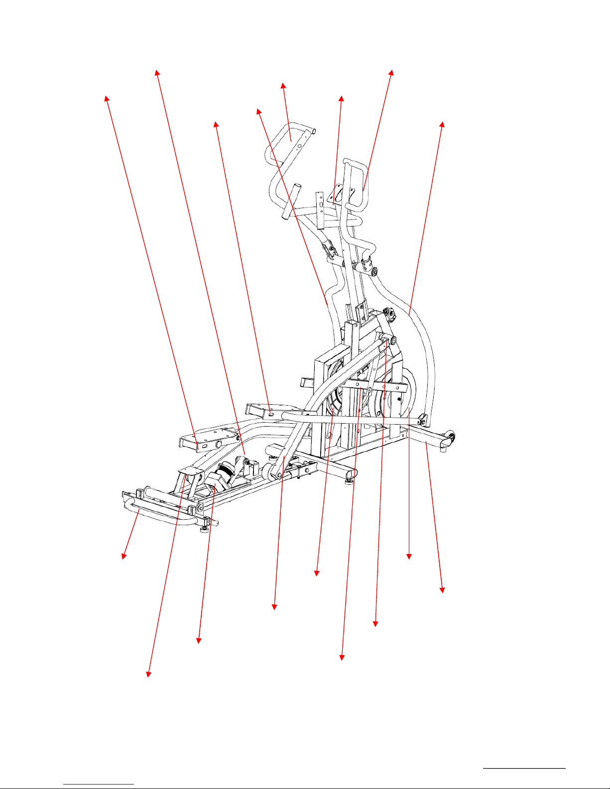
結構件 Steel parts
Main frame
Flywheel
Bushing Housing, Pedal Arm
Cross Bar
Pedal arm (R)
Drive Pulley
Incline motor
Rail assembly
Connecting arm (L)
Pedal arm (L)
Connecting arm (R)
Lower Swing arm (L)
upper Swing arm (L)
upper Swing arm (R)
Console mast
Lower Swing arm (R)
Rear frame

2. Electronic Parts
SSeerrvviiccee MMaannuuaal
l
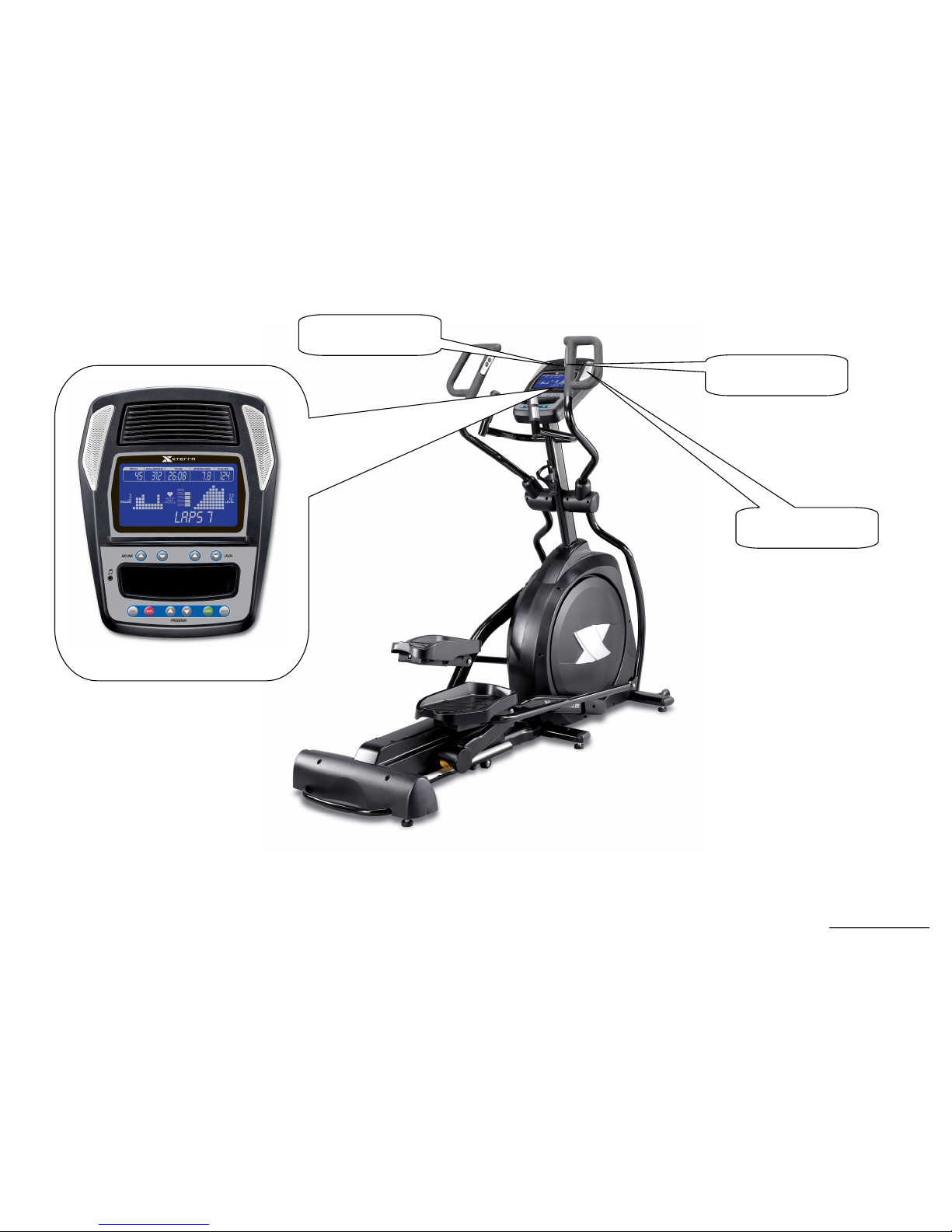
2.1 Upper Controllers
DISPLAY
Cooling FAN
THUMB SWITCH
Speaker
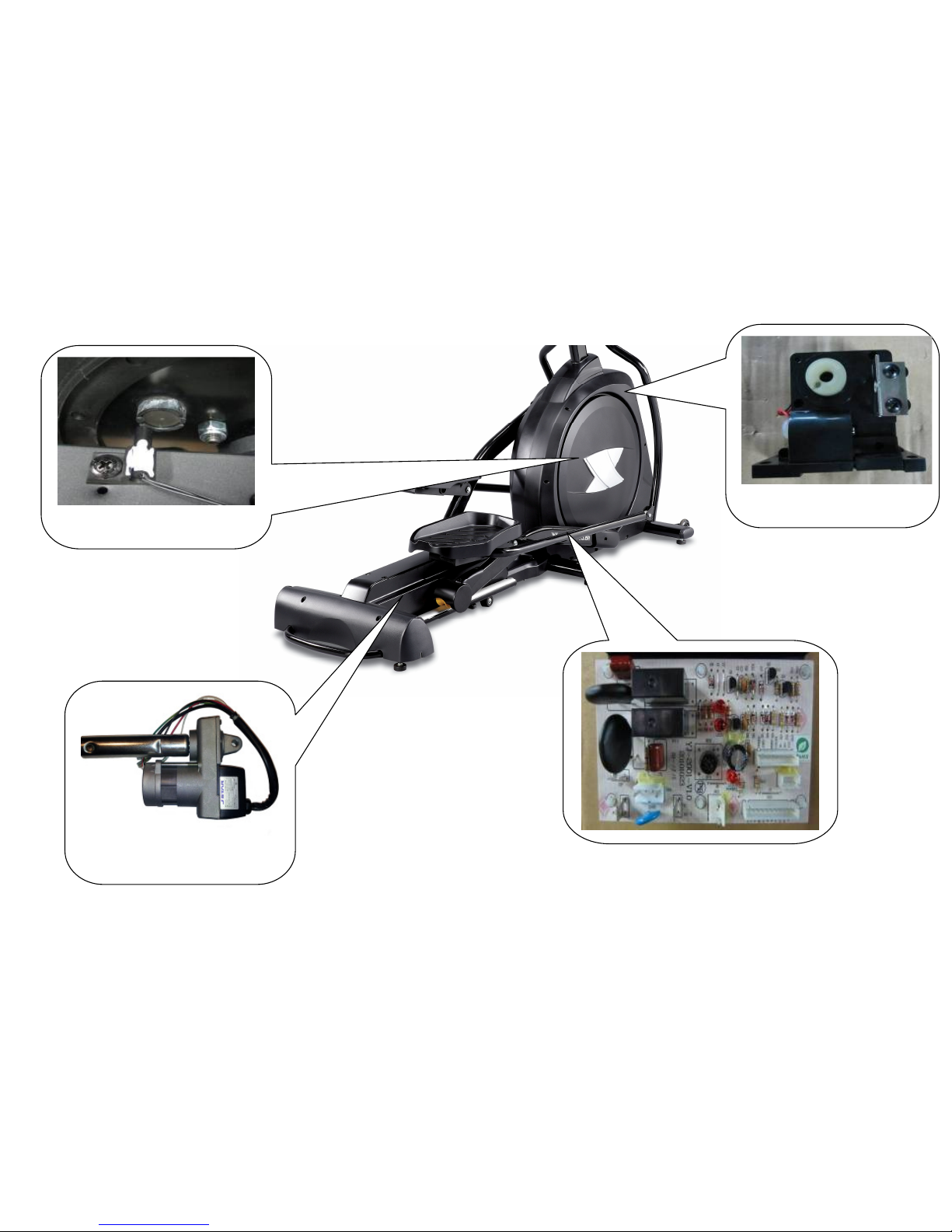
2.2. Lower Controller and Driver
SPEED SENSOR
INCLINE MOTOR
TENSION MOTOR

SSeerrvviiccee MMaannuuaal
l
3. Electrical Configurations

SSeerrvviiccee MMaannuuaal
l
C
ONSOLE:
Interface that controls all functions of the Elliptical.
M
AIN CONTROLLER
:
The circuit board consist of the DC power supply for console、incline driver and tension motor driver, link the console to output appropriate voltages
for tension motor that control the elliptical functions.
T
ENSION MOTOR
:
It can change to increase or decrease resistance level of brake.
I
NCLINE MOTOR:
This is an ac motor. User can to control variable elevation by console within main controller.
G
ENERAL INFORMATION
C
ONSOLE
Contains Key controls and LCD Display.
Main controller Include power supply 、 motor driver control circuit and incline control circuit.
T
ENSION MOTOR
Work voltage:DC 4.5~7.5V
Control resistance increases and decreases.
I
NCLINE MOTOR
This is a 120V volt AC motor.
Have four wires, red, black, white and green.
Has one 3 pins cable of position sensor.
If there is AC voltage on the Red wire (UP) the incline motor will increase the incline.
If there is AC voltage on the Black wire (DOWN) the incline motor will decrease the incline.
The White wire (COM) is neutral.
The green wire is ground.

SSeerrvviiccee MMaannuuaal
l
4. Elliptical Operation
SSeerrvviiccee MMaannuuaal
l
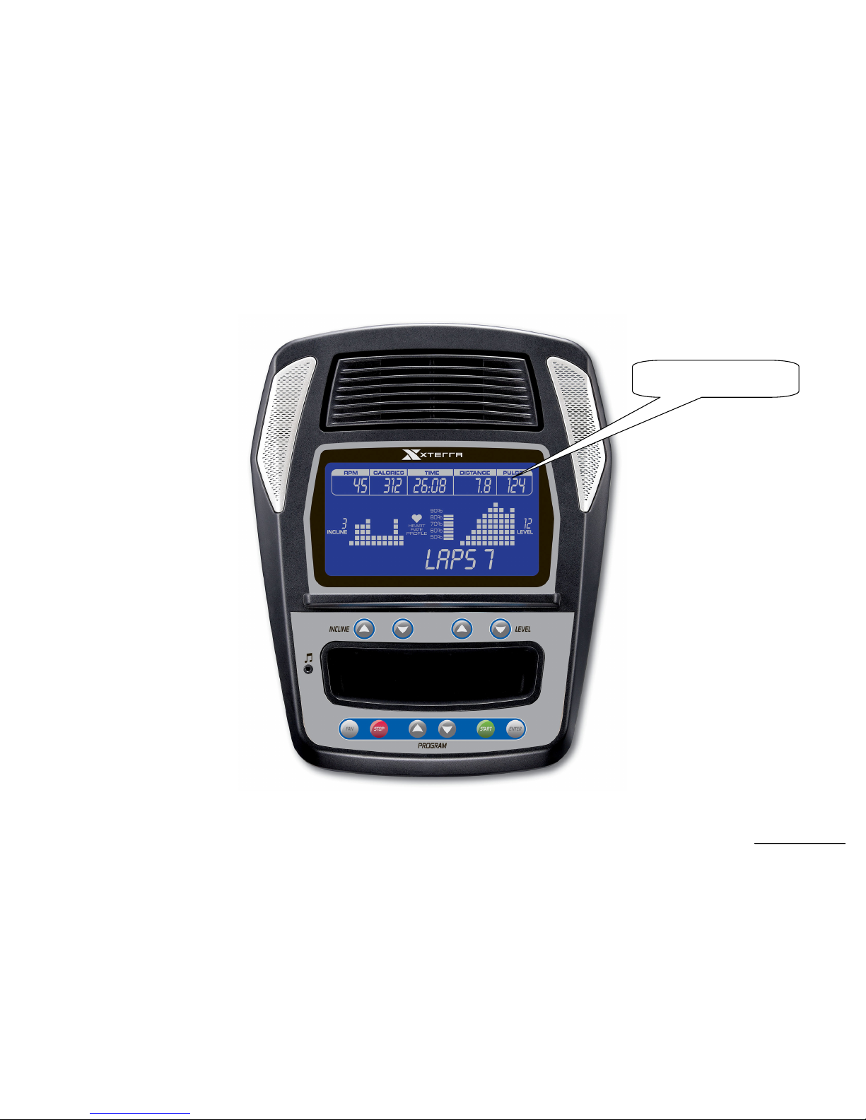
Display Windows
7.5” LCD Display
SSeerrvviiccee MMaannuuaal
l
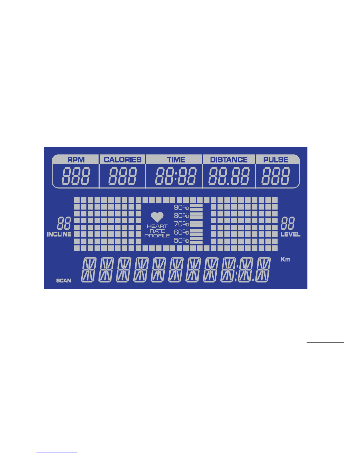
LCD Layout

SSeerrvviiccee MMaannuuaal
l
Operation
Window Display Mode
IDLE MODE
1.1 Dot matrix display shows program profiles page by page with each page lasts for 3 seconds for each program profile in order with message
window showing each name of the program profile.
SLEEP MODE
2.1 SLEEP MODE is preset ON(DISABLE)and can be set ON/OF under ENGINEER MODE.
2.2 When SLEEP MODE is set OFF, the console won’t go to sleep mode except turning off the power. When it is set OFF and if there is no RPM input
or no activation of any key button within 30 minutes, it enters SLEEP MODE.
2.3 In idle mode, hold and press “Enter”, “Stop” and “Display” keys for 2 seconds and use UP/DOWN keys to switch the sleep mode on and off th
en
press “Enter” key to return to idle mode.
2.4 W
hen in display mode LCD image clears and the background light turns off. Any key activation may wake up the console and reset and returns to
idle mode.
2.5 When in sleep mode, the resistance and incline levels are 1 and fan is turned off.
CHILD LOCK MODE
3.1 Child lock is preset off (disable) and may be set on or off in engineering mode.
3.2 When child lock is on: Turning on the power, the message window will show “CONSOLE LOCKED” and flashes twice then scrolls “CHILD
LOCK-ON PRESS START AND ENTER TO ENABLE OPERATION”. The user must press and hold both “Start” and “Enter” keys at the same time
for 2 seconds to unlock and enter idle mode for use.
3.3 When child lock is on, all key functions are disabled and unusable before unlock.
EXERCISE MODE(QUICK START)
4.1 When in idle mode, pressing “Start” key enters manual mode. Age and weight are with preset values and time will count up from 00:00. All
parameters will count up from 0 with resistance starts from 1.
4.2 Press program key (MANUAL、PROGRAM、USER1、USER2、HRC1、HRC2)to select a program then press “Start” key begin the selected
mode with preset parameters.
PAUSE MODE
5.1 Pressing “Stop” key during the workout enters pause mode and the exercise parameters will be recorded. Message window will show ”PAUSE”
with upper windows displaying the last moment parameters.
5.2 In pause mode when “PAUSE” has been shown for 5 seconds, it switches to scroll “PAUSED - PRESS START TO RESUME OR PRESS
BUTTON AGAIN TO END WORKOUT” once and recycles.

SSeerrvviiccee MMaannuuaal
l
5.3 When pause mode lasts for 10 minutes without any key is activated, it enters idle mode automatically.
5.4 The resistance and ramp incline levels returns to 1. When “Start” is pressed again, the pos
ition of the gear motor resumes and the ramp incline
return to the level just before pause.
END MODE
6.1 At the end of the program, message window will display “CONGRATULATIONS YOU HAVE COMPLETED YOUR WORKOUT PRESS THE
STOP KEY TO END OR A USER KEY TO SAVE” showing the workout data for 1minutes.
6.2 END MODE workout information:
6.2.1 In message window,『AVG SPD XX.X』、『AVG WATT XXX』、『AVG HR XXX』、『LAPS XX』、『ALT XXXX FT』each lasts for 3 seconds.
6.2.2 The message window is followed by displaying “CONGRATULATIONS YOU HAVE COMPLETED YOUR WORKOUT PRESS THE STOP
KEY TO END OR A USER KEY TO SAVE” with prompt of pressing start key to restart the program or pressing “Stop” key once to exit or
pressing “User” key and follow the MW instructions to save the program which has been finished by the custom user.
6.2.3 CAL will show the total calorie value of the workout, time window the total workout time and DIST window the total distance of the workout.
6.3 When TIME ends the count down to the end with end mode displayed for 1 minute without any key activation, it returns to idle mode automatically.
RESET MODE
7.1 Under idle mode (except console has been locked that must be unlocked prior to having the reset function), press “Stop” key for 3 seconds to
enter reset function and restart the system.

SSeerrvviiccee MMaannuuaal
l
Function
SPEED
Display the current speed in Kilometer mile per hour.
DISPLAY range is 0.0 to 99.9
WORK range is 0.0~99.9
Incline
Display the incline position from 0 to 20
DISPLAY range is 0 to 99.
WORK range is 0 to 20.
INCLINE preset value is 0 to 20.
Press “UP” or ”DOWN” to adjust incline, each increment and decrement is 1.
LEVEL
Display the incline position from 0 to 20
DISPLAY range is 0 to 99.
WORK range is 0 to 20.
LEVEL preset value is 0 to 20.
Press “UP” or ”DOWN” to adjust incline, each increment and decrement is 1.
TIME
TIME is either COUNT UP or COUNT DOWN. System preset is COUNT UP; if user sets the time then timer is COUNT DOWN.
DISPLAY range is 0:00 to 99:99.
WORK range is 0:00 to 99:59.
COUNT DOWN setup range is 10:00 to 99:00.
When TIME is set, the count will go to zero.
In RUN Mode, press “STOP” button to save value of time and enter “RUN Mode” again that value will continue count up time.
LAPS
Display the total working laps quantity.
DISPLAY range is 0 to 99.
WORK range is 0 to 99.
Displays total laps quantity.

SSeerrvviiccee MMaannuuaal
l
DISTANCE
Display the current distance in kilometer or Mile.
DISPLAY range is 00:00 to 99:00.
WORK range is 00:00 to 9999.
CALORIES
Displays the cumulative calories burned at any given time during your workout.
DISPLAY range is 00.0 to 999.
WORK range is 00.0 to 999.
PULSE
Displays the heart rate beat by using hand pulse or receiver. When use receiver, a chest belt must be worn.
DISPLAY range is 0 to 999.
WORK range is 40 to 220 BPM.
In RUN Mode, if the Elliptical doesn’t have a signal for 8 seconds then display value will become “- - - ”.
SSeerrvviiccee MMaannuuaal
l
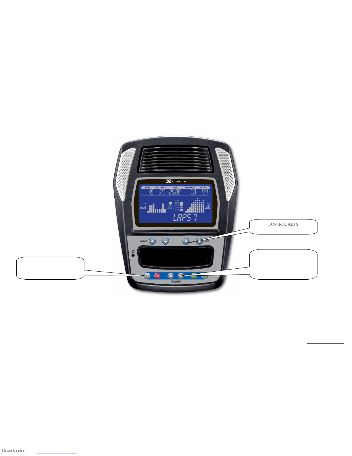
Function Button Locations
Fan Key
Cooling fan switch on or off
PROGRAM BUTTONS
(Manual, Adventure, Fatburn,
Xtreme, Interval, Glute Blast, X
Country, Fitness, 2 User, 2HR)
CONTROL KEYS

SSeerrvviiccee MMaannuuaal
l
Function Button In Main Mode
READY MODE
STOP button: Non-function.
START button: Pressing “ START ” button to start Elliptical, When pressing “START” button, there will be 3 second final count down on window
display, then machine starts running. In MANUAL, Elliptical starts at MIN LEVEL .
LEVEL UP button: If user doesn’t enter a setting then this button is non-functional.
LEVEL DOWN button: If user doesn’t enter a setting then this button is non- functional.
INCLINE UP button: If user doesn’t enter a setting then this button is non- functional.
INCLINE DOWN button: If user doesn’t enter a setting then this button is non- functional.
FAN button: It can to control ON/OFF for the fan.
ENTER KEY::::
Press this button to set data. If only START button is pressed without pressing ENTER button, the data is accepted.
Press this button to confirm the setting or the value entered.
RUN MODE
STOP button: press “STOP” button to stop Elliptical.
START button: non-functional.
ENTER button: non-functional.
LEVEL UP button: Press the button to increase your level and each increase is 1.
LEVEL DOWN button: Press the button to decrease your level and each decrease is 1.
INCLINE UP button: Press the button to raise position and each increase is 1, the maximum incline position is 20.
INCLINE DOWN button: Press the button to lower position and each decrease is 1, the minimum incline position is 0.
Fan button: It can to control ON/OFF for the fan.
DISPLAY KEY:
::
:
During the workout, press “Enter” key to switch the workout data. If the message displayed is the last data, pressing “Enter” key will light on
the scan icon and begin a 4-second cycling mode.
The cycling mode will begin with “PROGRAM NAME” followed by the items below:
『SPEED XX.XKPH』
『WATT XXX』
『LAPS XX』
『ALT XXXX FT』
『LEVEL XX』

SSeerrvviiccee MMaannuuaal
l
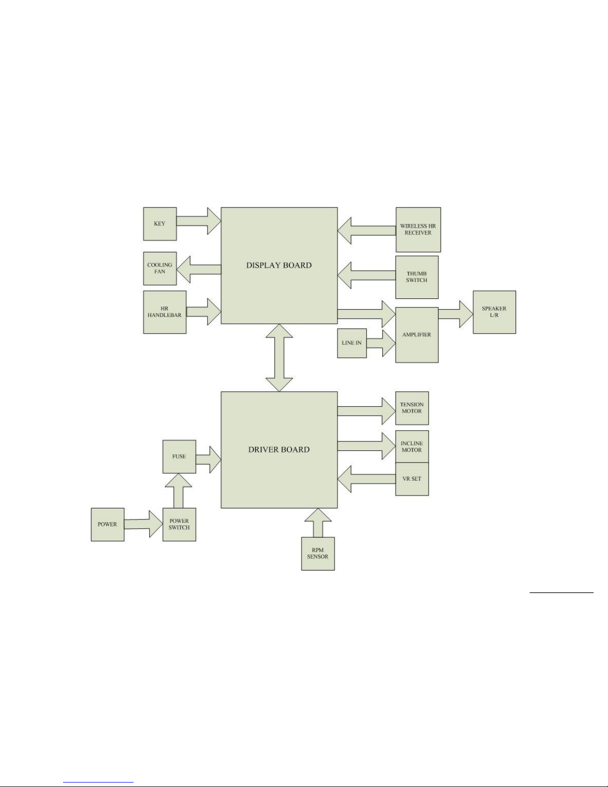
5. Elliptical Unit Block Diagrams
SSeerrvviiccee MMaannuuaal
l
Elliptical Configuration

SSeerrvviiccee MMaannuuaal
l
6. Elliptical Basic Connections and Wiring
SSeerrvviiccee MMaannuuaal
l
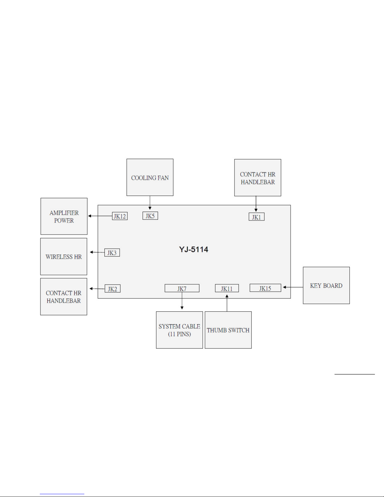
6.1 Display Board wire Connections
SSeerrvviiccee MMaannuuaal
l
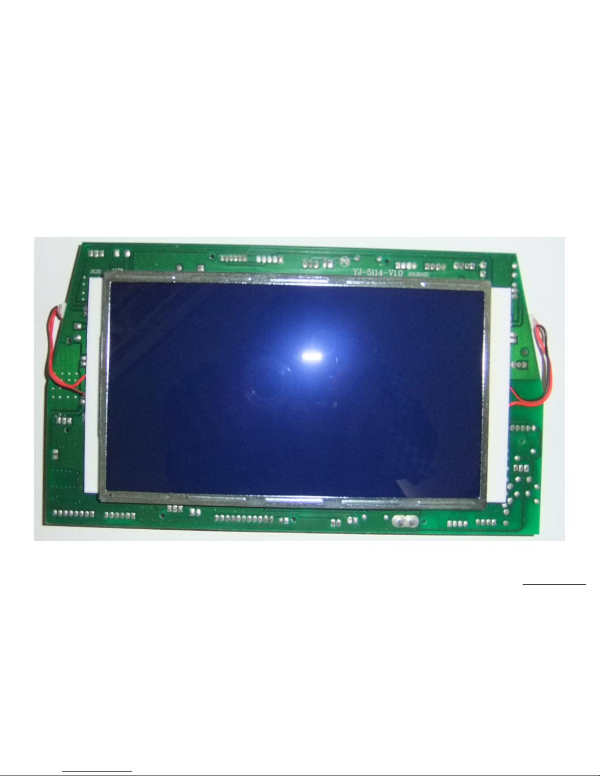
6.2 Display Board PCB Component Locations
PCB Board Top
SSeerrvviiccee MMaannuuaal
l
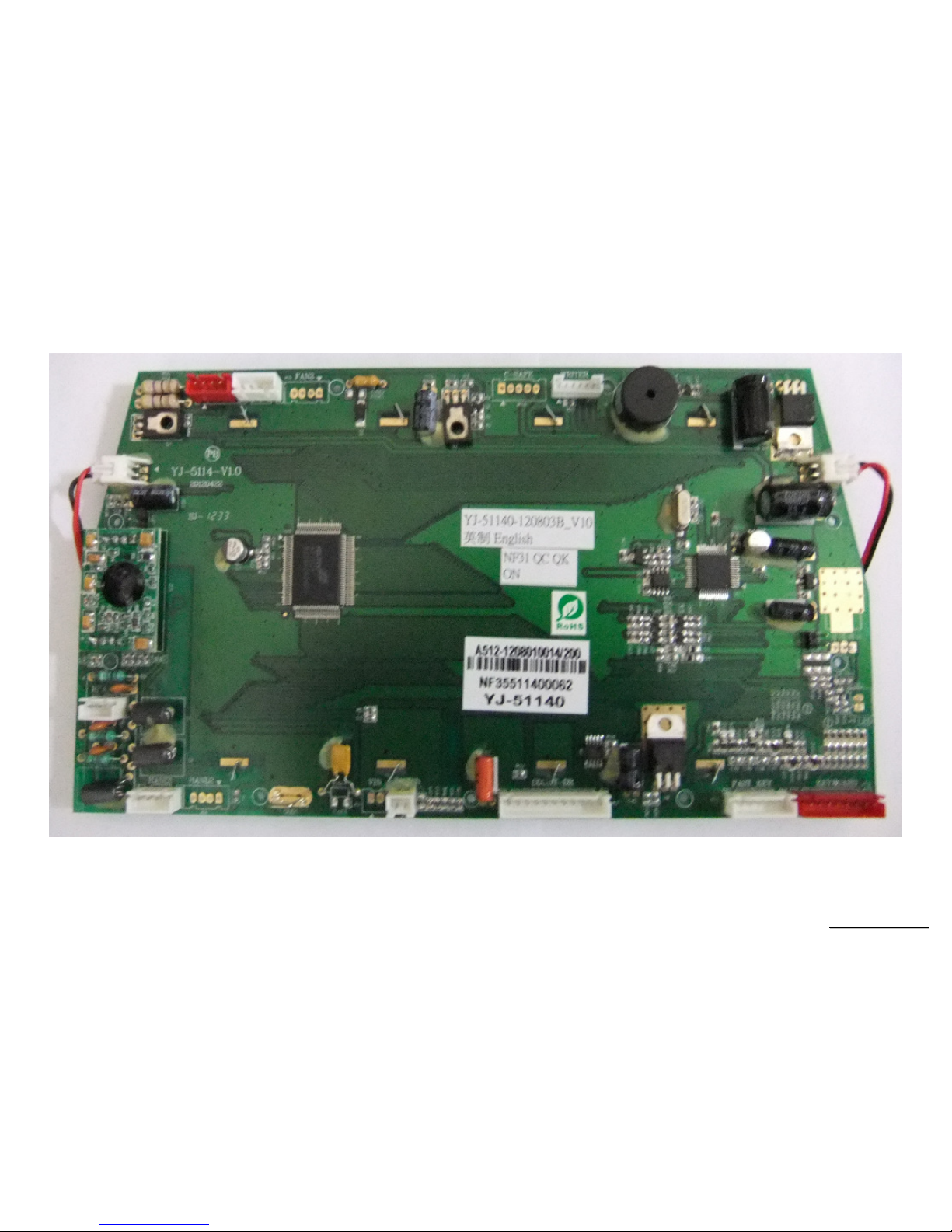
PCB Board Bottom
SSeerrvviiccee MMaannuuaal
l
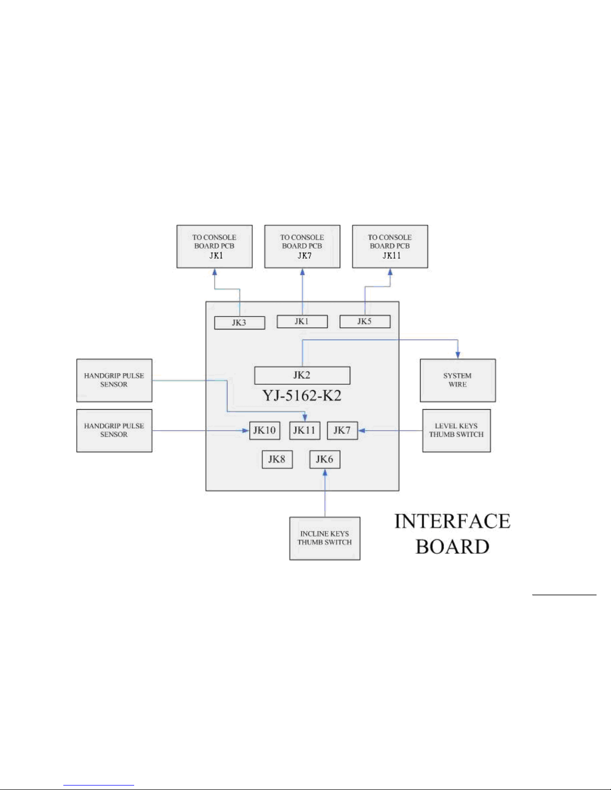
6.3 The console Interface Board wire Connections
SSeerrvviiccee MMaannuuaal
l
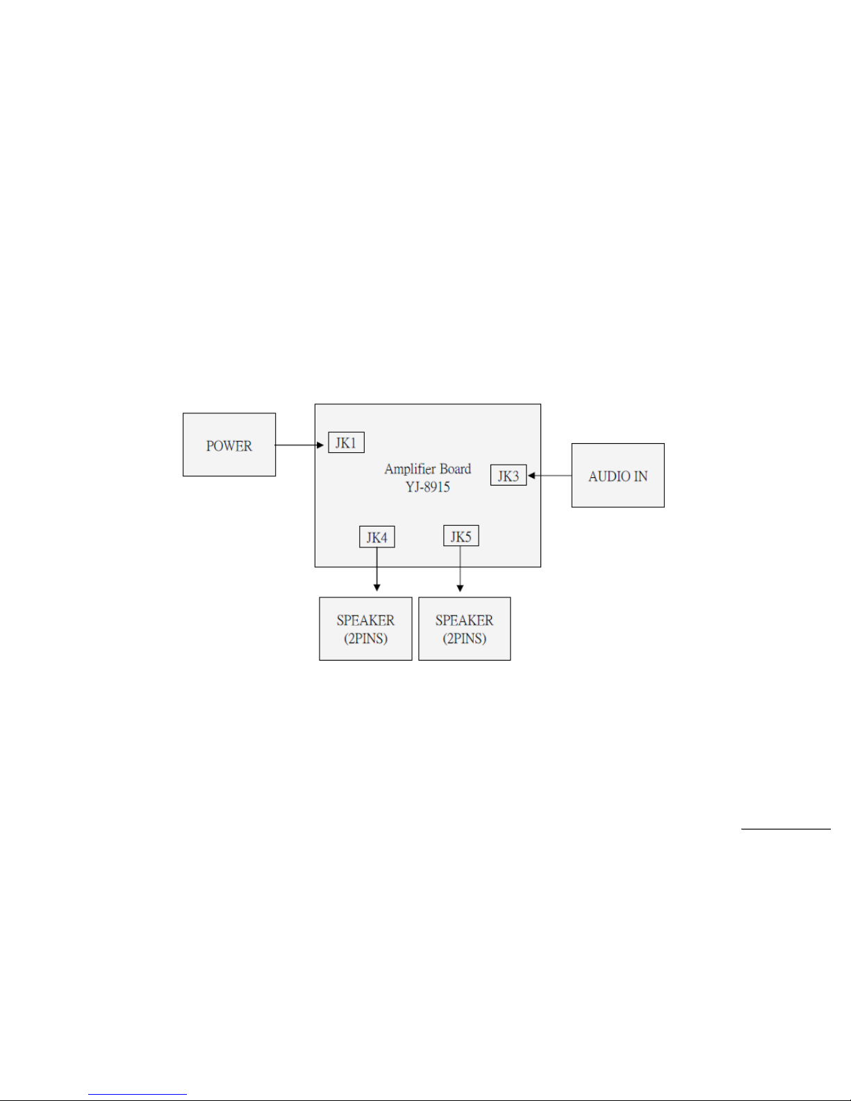
6.4 Amplifier Board wire Connections
 Loading...