

Dyaco XE330D-TE006, XE330D Service Manual
XE330D-TE006
Elliptical
Service Manual

SSeerrvviiccee MMaannuuaal
l
-1-
-----------------------------------------Table of Content-----------------------------------------------
1. XE330D Elliptical Outlines
2. Electronic Parts
2.1 Upper Controllers
2.2 Lower Controller and Driver
3. Electrical Configurations
4. Elliptical Operation
5. Elliptical Unit Block Diagrams
6. Elliptical Basic Connections and Wiring
6.1 Display Board Wire Connections
6.2 Display Board PCB Component Locations
6.3 The Console Interface Board Wire Connections
6.4 Amplifier Board Wire Connections
6.5 Tension Motor Connector Definition Function
7. Product Safety Instructions
7.1 Important Safety Instructions
7.2 Important Electrical Instructions
7.3 Important Grounding Instructions
8. Elliptical Error Messages and Troubleshooting for electronic Issues
8.1 Error Message: E2
8.2 Error Message: E1
8.3 Circuit Diagram
8.4 Troubleshooting Procedure Matrix for Electronic Issues

SSeerrvviiccee MMaannuuaal
l
-2-
9. Troubleshooting
9.1 Console Problem
9.2 Side Case & Round Disk Problem
9.3 Flywheel Problem
9.4 Poly-V Belt Problem
9.5 Swing Arm Problem
9.6 Connecting Arm Problem
9.7 Controller & Incline Motor Problem
9.8 Gear Motor Problem
10. Q & A
10.1 Noise
10.2 Slip Problem
10.3 Resistance & Incline Problem
10.4 Smooth Problem
11. Disassembling and Assembling of Parts
11.1 Console Replacement
11.2 Connecting Arm Replacement
11.3 Connecting Arm Replacement
11.4 Slide Wheel Replacement
11.4 Pedal Arm Replacement
11.5 Side Case Replacement
11.6 Cross Bar Replacement
11.7 Idler Wheel Replacement
11.8 Flywheel & Poly-V Belt Replacement
11.9 Drive Pulley replacement

SSeerrvviiccee MMaannuuaal
l
-4-
1. XE330D Elliptical Outlines
SSeerrvviiccee MMaannuuaal
l
-5-
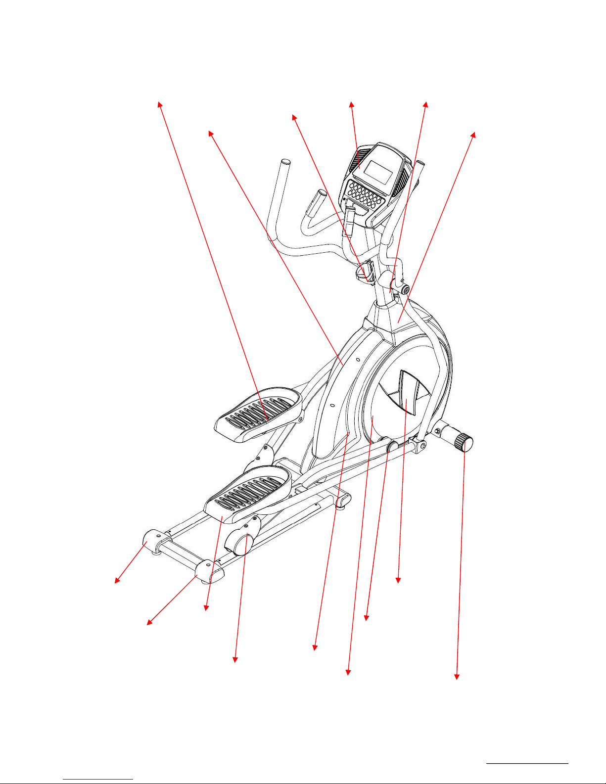
(1)Plastic parts
Left Side Case Console Mast Cover
Pedal(R)
Right Side Case
Drink Bottle Holder
Rear Stabilizer Cover (L)
Rear Stabilizer Cover (R)
Slide Wheel Cover
Round Disk Transportation Wheel
Round Disk Cover
Bushing Cover
Pedal(L) Console Cover Swing Arm Axle
SSeerrvviiccee MMaannuuaal
l
-6-
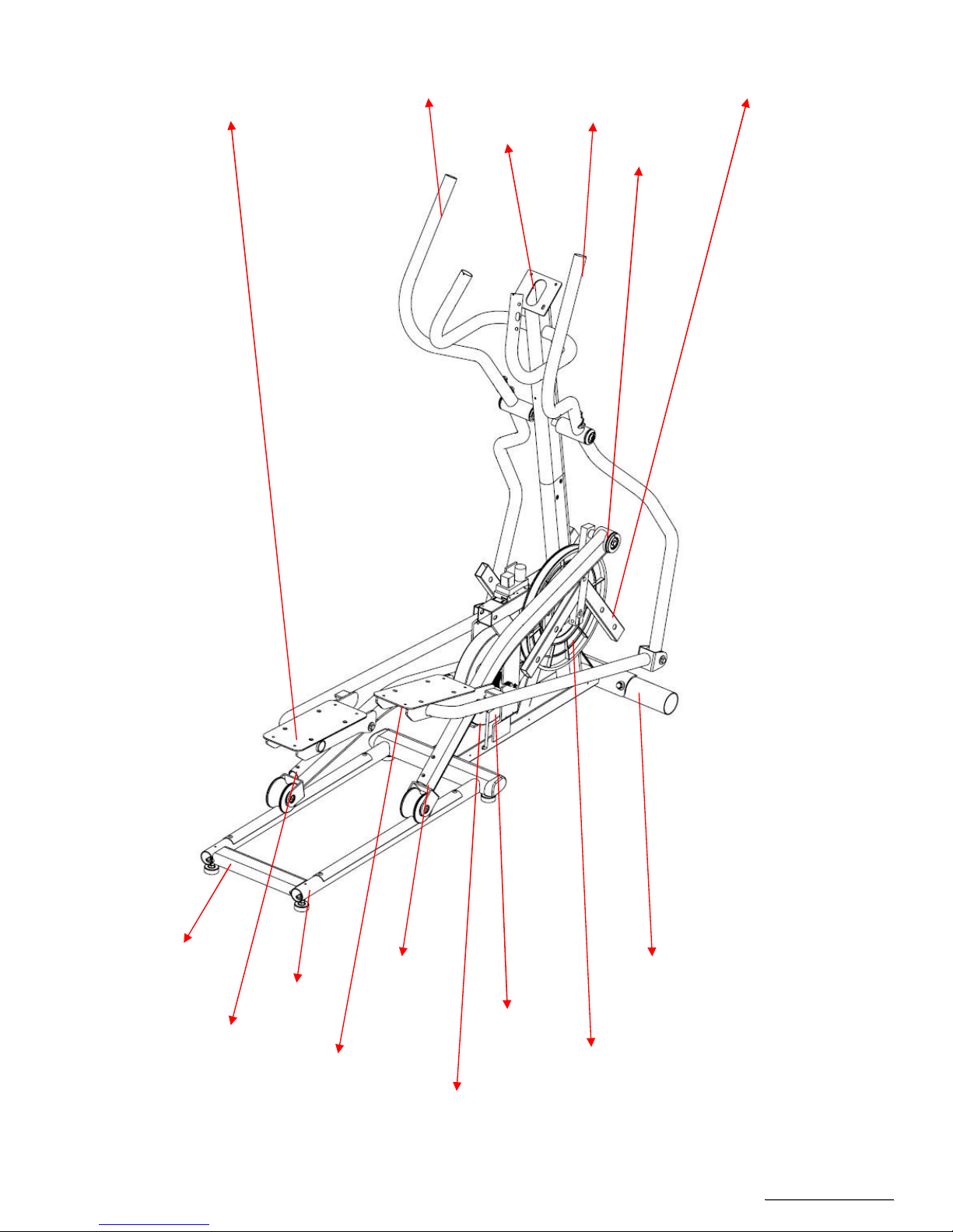
(2)Steel parts
Connecting Arm (L)
Lower Handle Bar (L) Cross Bar
Console Mast
Lower Handle Bar (R)
Bushing Housing, Pedal Arm
Rail Assembly
Pedal Arm(L)
Pedal Arm(R)
Rail Tube
Pedal Arm(R)
Connecting Arm (R)
Idler Wheel Assembly
Drive Pulley
Flywheel

SSeerrvviiccee MMaannuuaal
l
-7-
2. Electronic Parts
SSeerrvviiccee MMaannuuaal
l
-8-
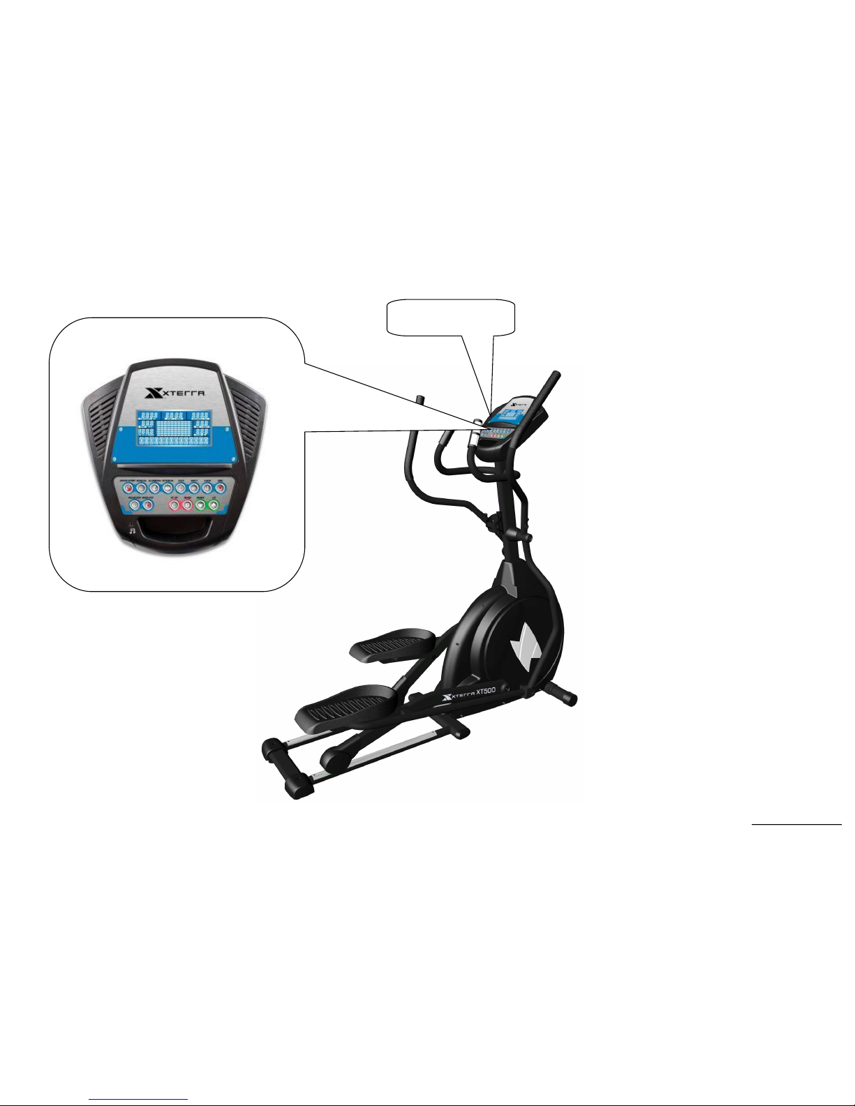
2.1 Upper Controllers
DISPLAY
Speaker
SSeerrvviiccee MMaannuuaal
l
-9-
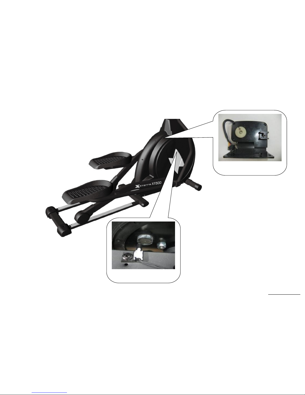
2.2. Lower Controller and Driver
SPEED SENSOR
TENSION MOTOR

SSeerrvviiccee MMaannuuaal
l
-10-
3. Electrical Configurations

SSeerrvviiccee MMaannuuaal
l
-11-
C
ONSOLE:
Interface that controls all functions of the Elliptical.
M
AIN CONTROLLER
:
The circuit board consist of the DC power supply for console、tension motor driver, link the console to output appropriate voltages for tension
motor that control the elliptical functions.
T
ENSION MOTOR
:
It can change to increase or decrease resistance level of brake.
G
ENERAL INFORMATION
C
ONSOLE
Contains Key controls and LCD Display.
T
ENSION MOTOR
Work voltage: DC 4.5~7.5V
Control resistance increases and decreases.

SSeerrvviiccee MMaannuuaal
l
-12-
4. Elliptical Operation
SSeerrvviiccee MMaannuuaal
l
-13-
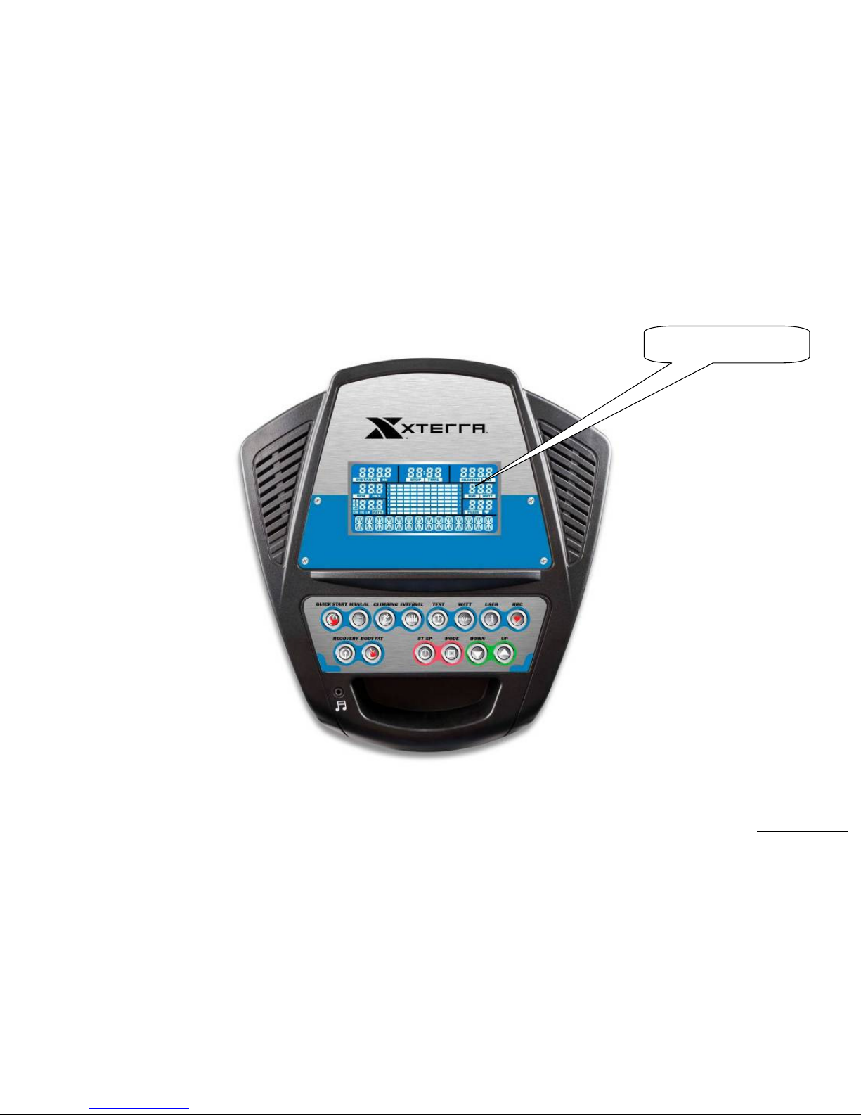
Display Windows
5.5” LCD Display
SSeerrvviiccee MMaannuuaal
l
-14-
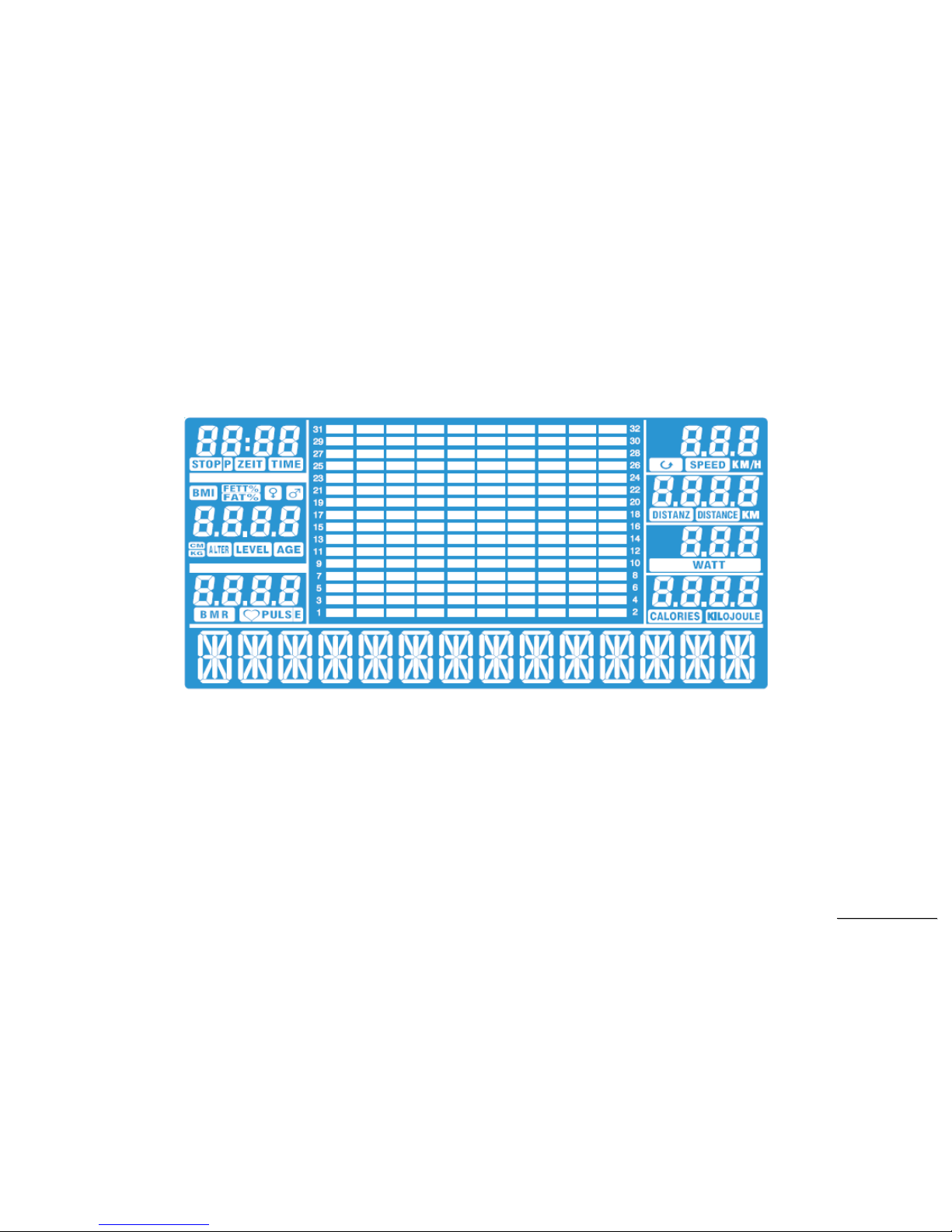
LCD Layout

SSeerrvviiccee MMaannuuaal
l
-15-
Operation
Window Display Mode
IDLE MODE
1.1 The DM displays “WELCOME” repeatedly and the MW displays “PRESS PROGRAM BUTTON AFTER EXERCISING” word series.
SLEEP MODE
2.1 SLEEP ON(ENABLE)is pre-set. When there is no input within 4 minutes, the unit enters SLEEP mode.
PAUSE MODE
3.1 Pressing STOP key during workout, the unit enters PAUSE mode and the exercising parameters are saved.
3.2 Under PAUSE mode, the WM keeps displaying “PRESS START BUTTON AFTER EXERCISING”.
3.3 PAUSE mode keeps for 4 minutes, if there is no input in 4 minutes, the unit enters SLEEP mode.
3.4 The resistance level returns to level 1. Pressing START key again, the gear motor returns the level before pause mode
RESET MODE
4.1 While under idle mode, pressing stop key for 3 seconds, the unit resets and restarts.

SSeerrvviiccee MMaannuuaal
l
-16-
Function
SPEED
Display the current speed in Kilometer mile per hour.
DISPLAY range is 0.0 to 99.9
WORK range is 0.0~99.9
LEVEL
Display the level position from 1 to 20
DISPLAY range is 0 to 9999.
WORK range is 1 to 20.
LEVEL preset value is 1 to 20.
Press “UP” or ”DOWN” to adjust level, each increment and decrement is 1.
TIME
TIME is either COUNT UP or COUNT DOWN. System preset is COUNT UP; if user sets the time then timer is COUNT DOWN.
DISPLAY range is 0:00 to 99:99.
WORK range is 0:00 to 99:59.
COUNT DOWN setup range is 10:00 to 99:00.
When TIME is set, the count will go to zero.
In RUN Mode, press “STOP” button to save value of time and enter “RUN Mode” again that value will continue count up time.
DISTANCE
Display the current distance in kilometer or Mile.
DISPLAY range is 00.0 to 99.9.
WORK range is 00.0 to 99.9.

SSeerrvviiccee MMaannuuaal
l
-17-
CALORIES
Displays the cumulative calories burned at any given time during your workout.
DISPLAY range is 0 to 9999.
WORK range is 0 to 9999.
PULSE
Displays the heart rate beat by using hand pulse or receiver. When use receiver, a chest belt must be worn.
DISPLAY range is 0 to 9999.
WORK range is 40 to 220 BPM.
In RUN Mode, if the Elliptical doesn’t have a signal for 8 seconds then display value will become “P ”.
SSeerrvviiccee MMaannuuaal
l
-18-
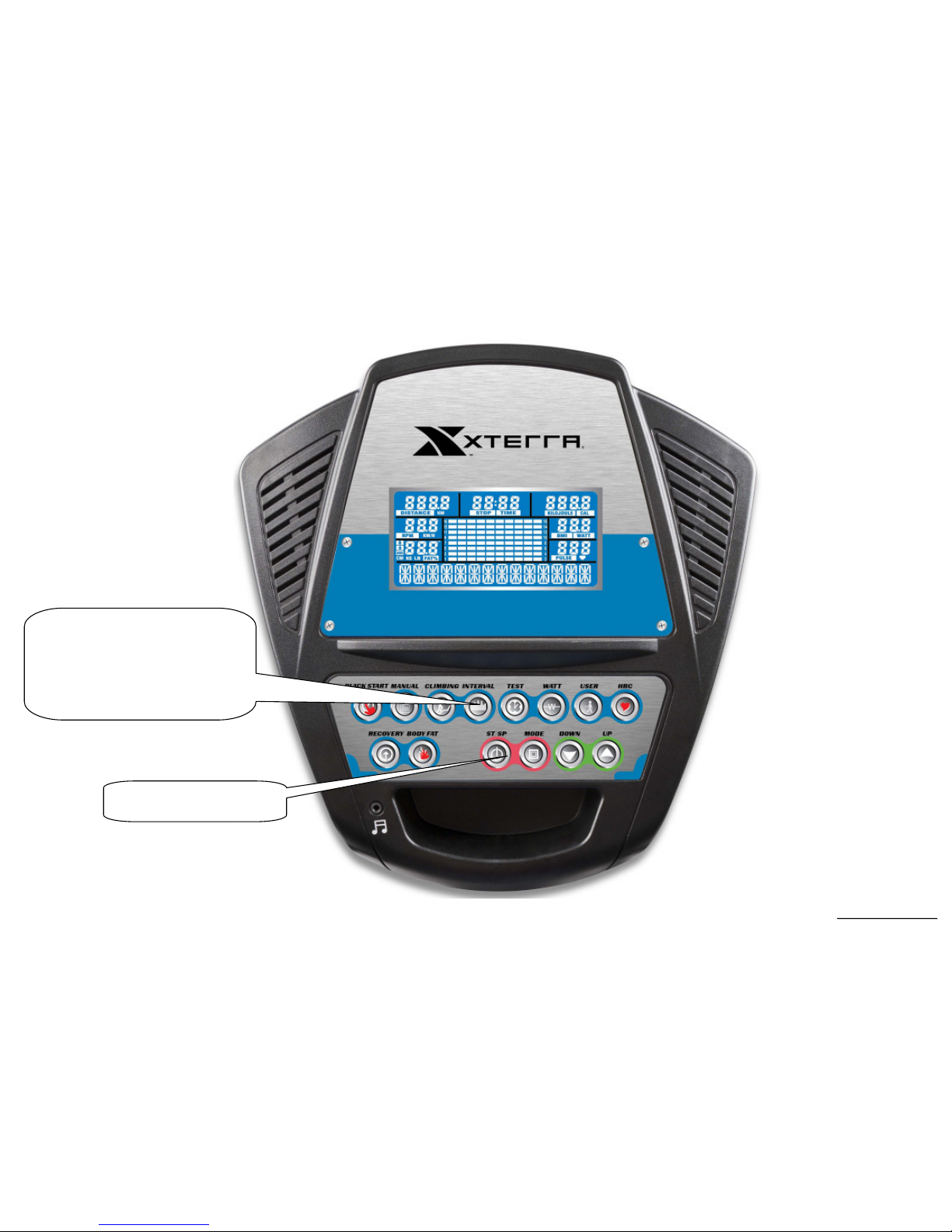
Function Button Locations
PROGRAM BUTTONS
(Quick_Start,Manual,CLIMBING,
Interval,TEST,WATT_CONTROL
,HRC,User,RECOVERY,BODY
FAT)
CONTROL KEYS

SSeerrvviiccee MMaannuuaal
l
-19-
Function Button In Main Mode
READY MODE
START/STOP button: This button is non-functional.
UP button: If user doesn’t enter a setting then this button is non-functional.
DOWN button: If user doesn’t enter a setting then this button is non- functional.
MODE button: While in program setting, pressing this button goes to next setting parameter.
RUN MODE
START/STOP button: press “START/STOP” button to stop Elliptical.
MODE button: non-functional.
UP button: Press the button to increase your level and each increase is 1.
DOWN button: Press the button to decrease your level and each decrease is 1.

SSeerrvviiccee MMaannuuaal
l
-20-
5. Elliptical Unit Block Diagrams
 Loading...