

Dyaco ST95-YT007 Service Manual
SSeerrvviiccee MMaannuuaal
l
ST95-YT007
Treadmill
Service Manual
(110~120V & 220~230V)

SSeerrvviiccee MMaannuuaal
l
-1-
-------------------------------------------Table of Contents-------------------------------------------
1. ST95 Treadmill Outlines
2. Electronic Parts
2.1 Upper Controllers
2.2 Lower Controller and driver
3. Electrical Configuration
4. ST95 Treadmill Operation
5. Unit Block Diagrams
6. Basic Connections and Wiring
6.1 Display Board Wire Connections
6.2 Display Board PCB Component Locations
6.3 Amplifier Board Wire Connections
6.4 Driver Board Wire Connections
6.5 Driver Board PCB Component Locations
6.6 Driver Board LED Indicator Locations
6.7 Controller Indicator LED Debugging
6.8 Driver Board Function
7. Product Safety Instructions
7.1 Important Safety Instructions
7.2 Important Electrical Instructions
7.3 Important Grounding Instructions
8. Error Messages and Troubleshooting for electronic Issues
8.1 Error Message: LS1/ LOW SPEED
8.2 Error Message: E1/ RAM ERROR
8.3 Error Message: INCLINE E2
8.4 Circuit diagram
8.5 Calibration Procedure
8.6 MAINTENANCE MENU
8.7 Fuse Replacement
8.8 Troubleshooting Procedure Matrix for Electronic Issues
9. Treadmill Folding/Unfolding and Transport
10. General Maintenance
10.1 Tread Belt and Deck
11. Installation of the Incline Motor
12. Disassembling and assembling of parts
12.1 Lower Controller replacement

SSeerrvviiccee MMaannuuaal
l
-2-
12.2 Console Replacement
12.3 Motor Replacement
12.4 Power Cord Replacement
12.5 AC Power Switch Replacement
12.6 Front/ Rear Roller Replacement
12.7 Running Deck/ Belt & Cushion Replacement
12.8 Speed Sensor Replacement
12.9 Incline Motor Replacement

SSeerrvviiccee MMaannuuaal
l
-3-
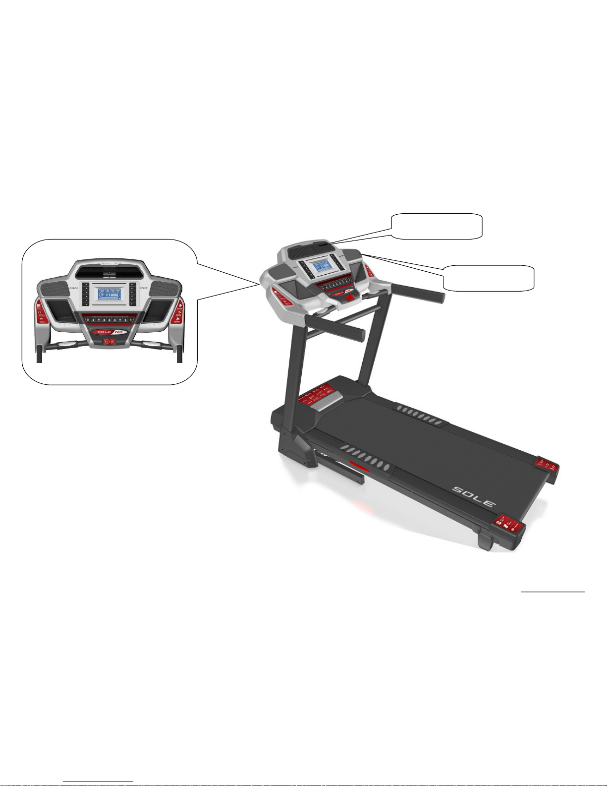
1. ST95 Treadmill Outlines
SSeerrvviiccee MMaannuuaal
l
-5-
Console
Cooling FAN
Speaker

SSeerrvviiccee MMaannuuaal
l
-6-
2. Electronic Parts
SSeerrvviiccee MMaannuuaal
l
-7-
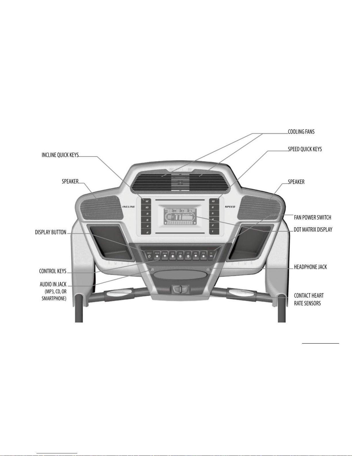
2.1 Upper Controllers
SSeerrvviiccee MMaannuuaal
l
-8-
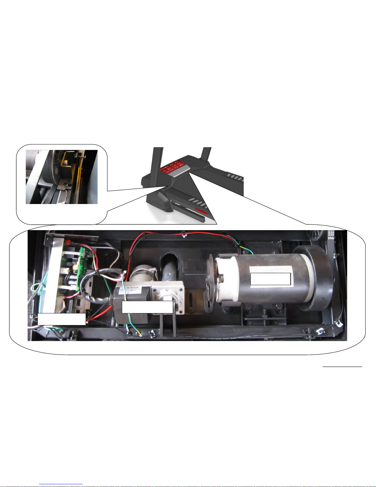
2.2. Lower Controller and Driver
Driver System(Motor/Controller/Incline Motor)
SPEED SENSOR
DC MOTOR
Motor Controller
Incline Motor & VR

SSeerrvviiccee MMaannuuaal
l
-9-
3. Electrical Configurations

SSeerrvviiccee MMaannuuaal
l
-10-
S
AFETY KEY
:
To fits on the Console that activate all functions. If no safety key, console can not be controlled.
C
ONSOLE:
Interface that controls all functions of the treadmill.
M
AIN CONTROLLER
:
The circuit board consist of the DC power supply for console、incline driver and DC motor driver, link the console to output appropriate voltages for
motor that control the treadmill functions.
T
READMILL MOTOR
:
This is a variable speed for DC motor. To control the 0 –90 voltages on the main controller, it can to increase or decrease speed of running belt.
I
NCLINE MOTOR:
This is an ac motor. User can to control variable elevation by console within main controller.
G
ENERAL INFORMATION
C
ONSOLE
Contains Key controls and LCD Display.
Main controller Include power supply 、 motor driver control circuit and incline control circuit.

SSeerrvviiccee MMaannuuaal
l
-11-
T
READMILL MOTOR
It’s a variable speed on 0-90 volt DC motor.(for 110V model)
Have three wires red, black and green.
If there is DC voltage on the Red (white) wire (M+) the treadmill motor will turn clockwise.
If there is DC voltage on the Black wire (M-) the treadmill motor will turn counter-clockwise.
The higher the voltage the faster the motor turns
The green wire is ground.
I
NCLINE MOTOR
This is a 120 volt AC motor.
Have four wires, red, black, white and green.
Has one 3 pins cable of position sensor.
If there is AC voltage on the Red wire (UP) the incline motor will increase the incline.
If there is AC voltage on the Black wire (DOWN) the incline motor will decrease the incline.
The White wire (COM) is neutral.
The green wire is ground.

SSeerrvviiccee MMaannuuaal
l
-12-
4. ST95 Treadmill Product Operation
SSeerrvviiccee MMaannuuaal
l
-13-
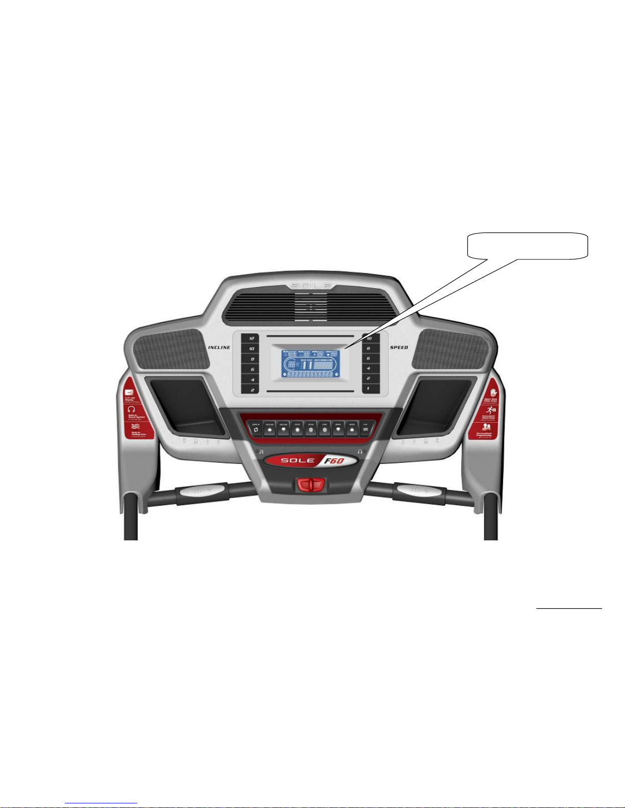
Display Windows
5.5” LCD Display
SSeerrvviiccee MMaannuuaal
l
-14-
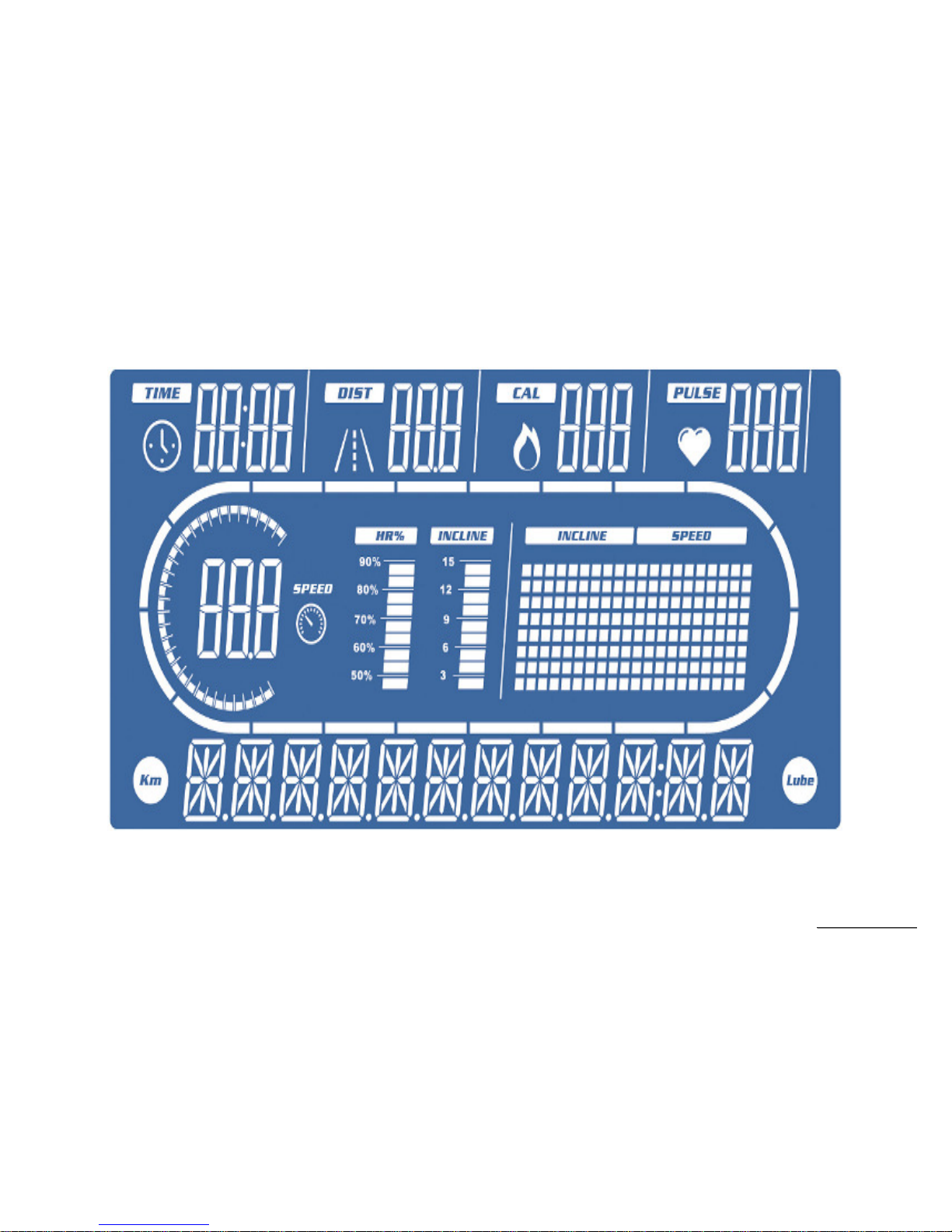
LCD Layout

SSeerrvviiccee MMaannuuaal
l
-15-
Operation
Window Display Mode
OFF Mode
When user doesn’t insert the SAFETY KEY on the console, the treadmill enters the OFF Mode and all windows will appear blank.
READY Mode
When the treadmill is ON and SAFETY KEY is inserted in console, the message window will show "USE SPEED UP OR DOWN KEY TO
SELECT A PROGRAM". Press START button to start treadmill on Manual Mode.
SLEEP Mode
In SLEEP Mode, if anyone
button is pressed then the treadmill enters READY Mode.
RUN Mode
In RUN Mode, pressing the “STOP” button and removing the SAFETY KEY will cause the treadmill stop instantly and enter OFF Mode.
Function
SPEED
Display the current speed in Kilometer mile per hour.
DISPLAY range is 0.0 to 99.9
WORK range is 0.5~12mph
Press “FAST” or ”SLOW” to adjust speed, each increment and decrement is 0.1 km/h(mph).

SSeerrvviiccee MMaannuuaal
l
-16-
Incline
Display the incline position from 0 to 15
DISPLAY range is 0 to 99.
WORK range is 0 to 15.
INCLINE preset value is 0 to 15.
Press “UP” or ”DOWN” to adjust incline, each increment and decrement is 1.
TIME
TIME is either COUNT UP or COUNT DOWN. System preset is COUNT UP; if user sets the time then timer is COUNT DOWN.
DISPLAY range is 0:00 to 99:99.
WORK range is 0:00 to 99:59.
COUNT DOWN setup range is 10:00 to 99:00.
When TIME is set, the count will go to zero.
In RUN Mode, press “STOP” button to save value of time and enter “RUN Mode” again that value will continue count up time.
LAPS
Display the total working laps quantity.
DISPLAY range is 0 to 99.
WORK range is 0 to 99.
Displays total laps quantity.
DISTANCE
Display the current distance in kilometer or Mile.
DISPLAY range is 0.00 to 99.9.
WORK range is 0.00 to 99.9.
CALORIES
Displays the cumulative calories burned at any given time during your workout.
DISPLAY range is 0.0 to 999.
WORK range is 0.0 to 999.
PULSE
Displays the heart rate beat by using hand pulse or receiver. When use receiver, a chest belt must be worn.
DISPLAY range is 0 to 999.
WORK range is 20 to 220 BPM.
In RUN Mode, if the treadmill doesn’t have a signal for 8 seconds then display value will become “0 ”.
SSeerrvviiccee MMaannuuaal
l
-17-
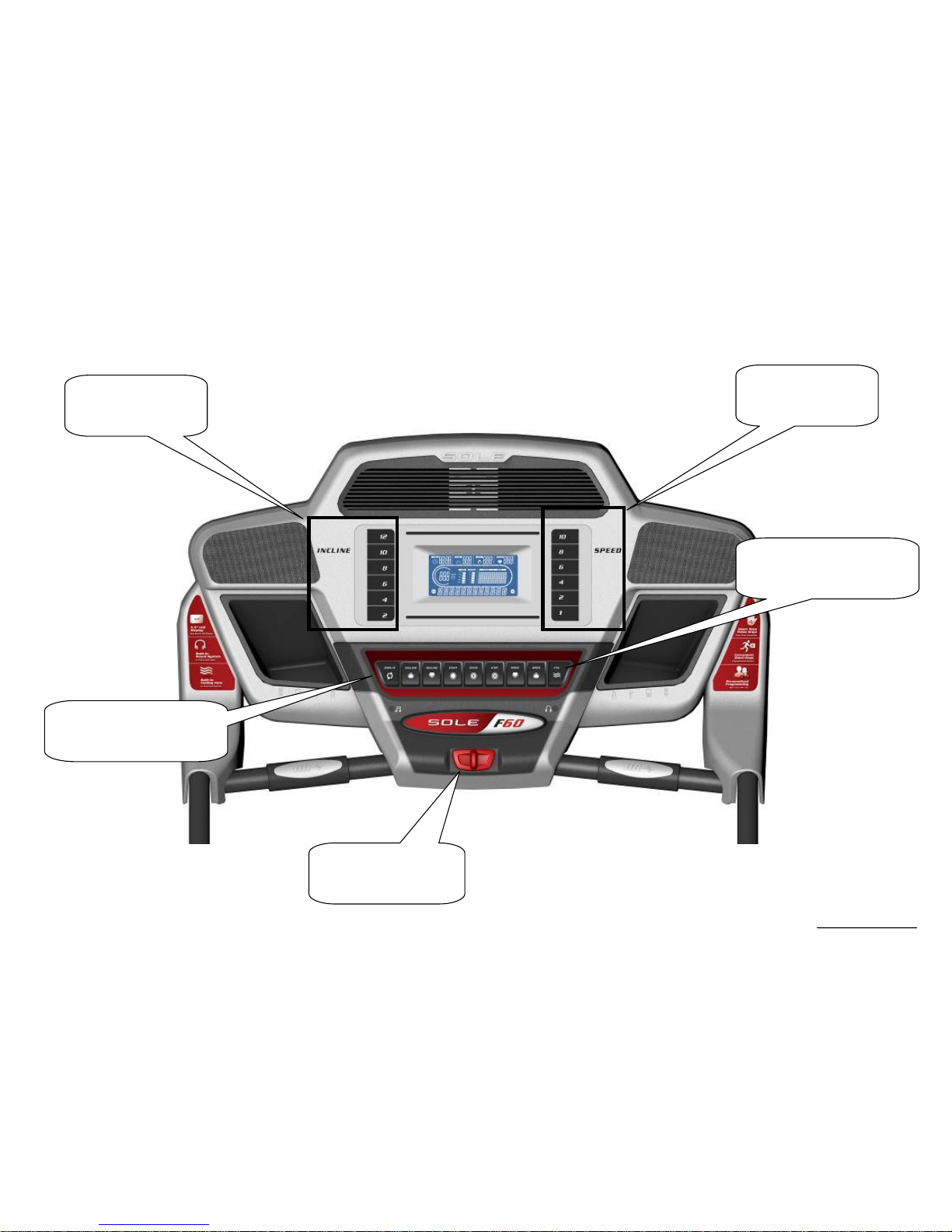
Function Button Locations
Speed quick keys
1/2/4/6/8/10
Incline quick keys
2/4/6/8/10/12
Fan Key
Cooling fan switch on or off
Function Key
Set data function
Safety Key
Emergency function

SSeerrvviiccee MMaannuuaal
l
-18-
Function Button In Main Mode
READY MODE
SAFETY KEY: Fit safety key in right position to power on the computer. When safety key is pulled away from its position, the computer will be
automatically shut down.
STOP button: Non-function.
START button: Pressing “ START ” button to start treadmill, When pressing “START” button, there will be 3 second final count down on window
display, then machine starts running. In MANUAL, treadmill starts at MIN SPEED and treadmill starts at program preset value in PROGRAM.
ENTER button: Press “ENTER” button to change each function. MANUAL can set using time, Pre-set PROGRAM can set using time and speed,
Heart Rate Control 1~2 can set time, age and the value of heart rate. User Program 1~2 can set time, speed and incline.
FAST button: If user doesn’t enter a setting then this button is non-functional.
SLOW button: If user doesn’t enter a setting then this button is non- functional.
UP button: If user doesn’t enter a setting then this button is non- functional.
DOWN button: If user doesn’t enter a setting then this button is non- functional.
SPEED RAPID button: 5 preset buttons for rapid speed: 1,2,4,6,8,10.
INCLINE RAPID button: 5preset buttons for rapid incline: 2, 4, 6, 8, 10,12 .
FAN button: It can to control ON/OFF for the fan.
DISPLAY KEY::::
You could select the profile of SPEED or INCLINE by pressing DISPLAY key when selecting the programs (P0~P5, U1~U2).
ENTER KEY::::
Press ENTER key enter to parameter setting, confirm each setting or modification by pressing ENTER key. Press START key to finish the setting.
You could change the display of DISPLAY MODE by pressing ENTER key. The preset display profile is SPEED profile and cycling rotation is
SPEED profileINCLINE profileSCAN (SPEED profileINCLINE profileSPEED profile each three seconds).

SSeerrvviiccee MMaannuuaal
l
-19-
RUN MODE
SAFETY KEY: When safety key is pulled away from its position, the computer will be automatically shut down.
STOP button: press “STOP” button to stop treadmill.
START button: non-functional.
ENTER button: non-functional.
FAST button: Press the button to increase your speed and each increase is 0.1kph(0.1mph). If button is pressed continuously then speed
increases to MAX SPEED quickly.
SLOW button: Press the button to decrease your speed and each decrease is 0.1kph(0.1mph). If button is pressed continuously then speed
decreases to MIN SPEED quickly.
UP button: Press the button to raise position and each increase is 1, the maximum incline position is 12.
DOWN button: Press the button to lower position and each decrease is 1, the minimum incline position is 0.
SPEED RAPID button: Speed will set to 1,2,4,6,8,10. quickly.
INCLINE RAPID button: Incline will set to 2, 4, 6, 8, 10,12 position quickly.
Fan button: It can to control ON/OFF for the fan(Optional).
DISPLAY KEY::::
You could select the profile of SPEED or INCLINE by pressing DISPLAY key when selecting the programs (P0~P5, U1~U2).
Press DISPLAY key to switch the exercise data shown on the message window when you are workout. At the end of the display cycle, there is
a SCAN MODE, where system will scan and display information automatically every four seconds. The information displayed is as follows:
PROFILE NAME
PACE XX:XX
INCLINE 1~15
LAPS XX
VERT XXXX FT / M
SEG TIME X:XX
MAX SPEED XX.X(only in HRC MODE will not show this string)
DATA SCAN (Display two seconds)

SSeerrvviiccee MMaannuuaal
l
-20-
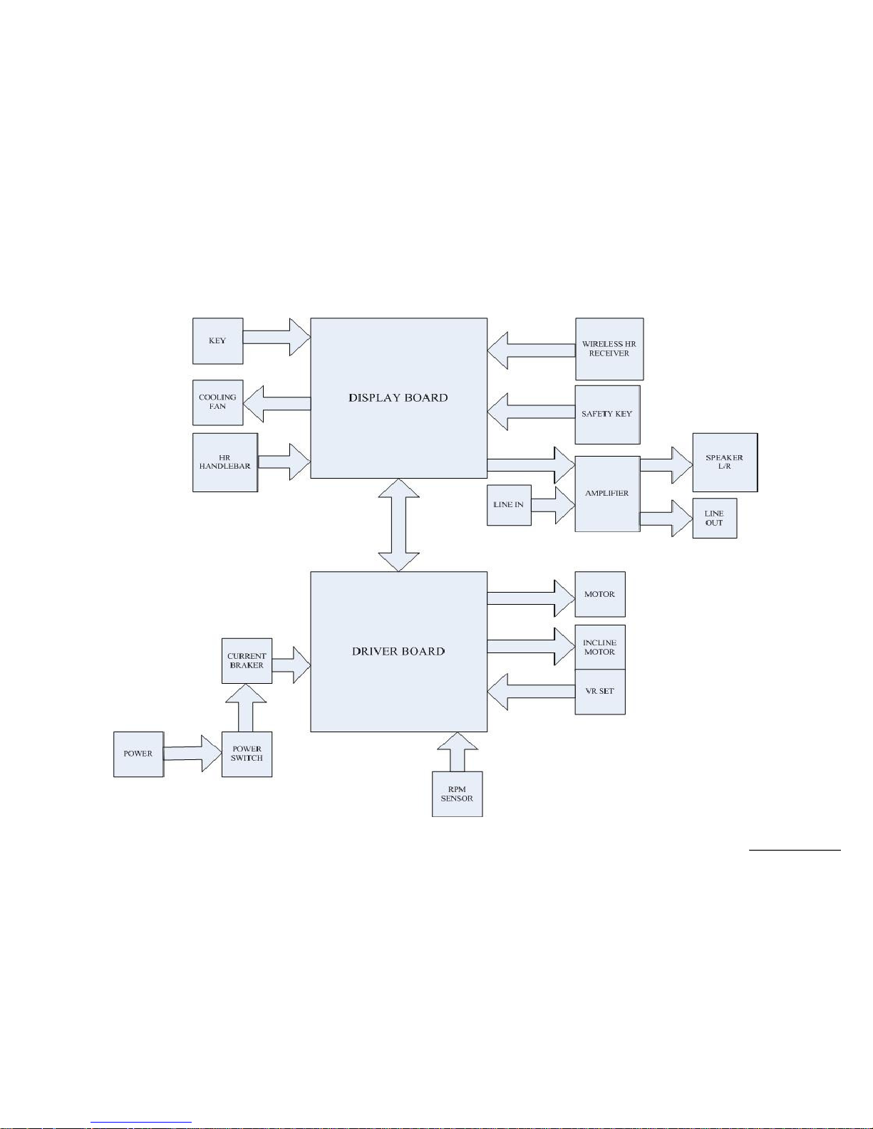
5. Unit Block Diagrams
SSeerrvviiccee MMaannuuaal
l
-21-
Treadmill Configuration

SSeerrvviiccee MMaannuuaal
l
-22-
6. Basic Connections and Wiring
SSeerrvviiccee MMaannuuaal
l
-23-
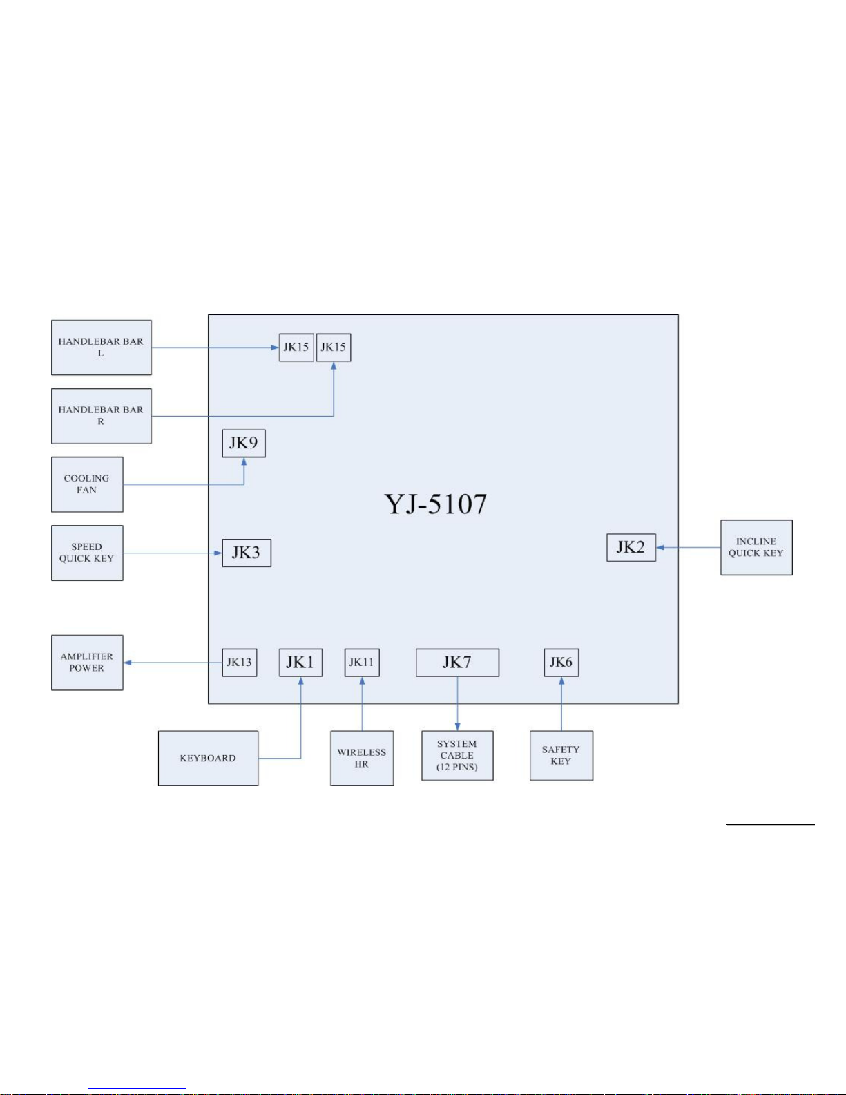
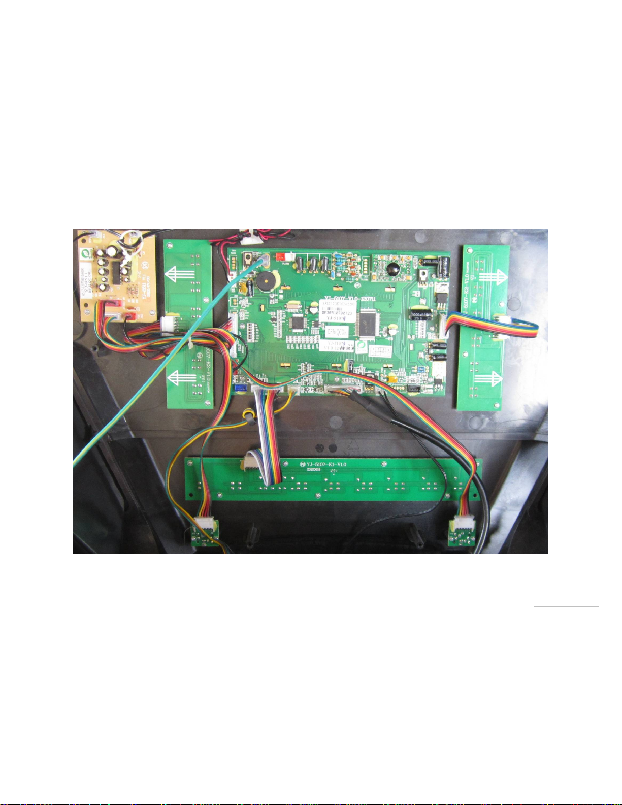
6.1 Display Board wire Connections
SSeerrvviiccee MMaannuuaal
l
-24-
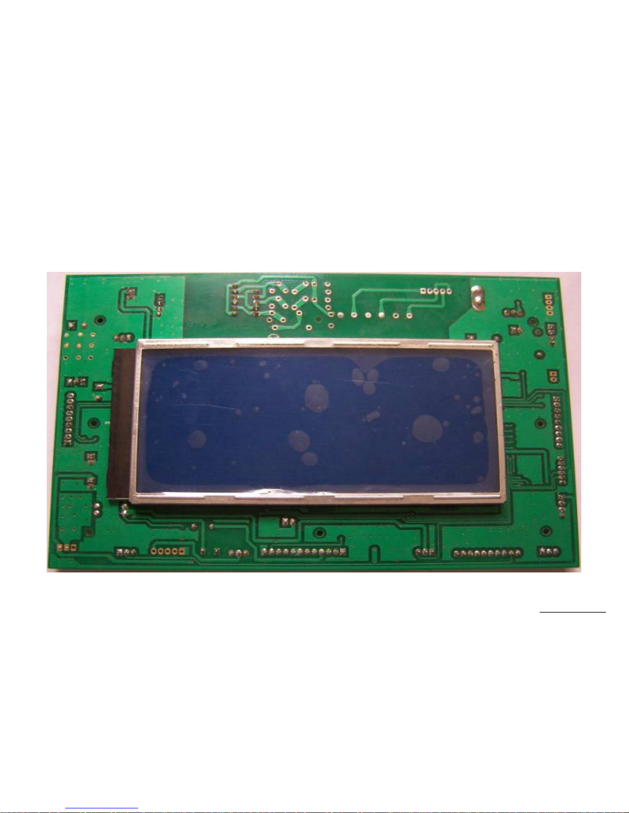
6.2 Display Board PCB Component Locations
PCB Board Top
SSeerrvviiccee MMaannuuaal
l
-25-
PCB Board Bottom
 Loading...