

Dyaco SU136-YB02, SR147-YB02 Service Manual
SSeerrvviiccee MMaannuuaal
l
1
SU136-YB02 &
SR147-YB02
Service Manual

SSeerrvviiccee MMaannuuaal
l
2
-------------------------------------------Table of Contents--------------------------------------
1. Upper & Recumbent Controllers Outlines
SU136 Outlines
SU136 Skeleton
SR147 Outlines
SR147 Skeleton
2. Electronic Parts
SU136 Upper Controllers
SR147 Recumbent Controllers
SU136 Lower Controller and Driver
SR147 Lower Controller and Driver
3. Electrical Configurations
4. Product Operation
5. Unit Block Diagrams
6. Basic Connections and Wiring
7. Product Safety Instructions
8. Error Messages / Troubleshooting
9. SU136-YB02 Troubleshooting
9-1 Console
9-2 Handle Bar and Console Mast
9-3 Seat and Sliding Seat Mount
9-4 Crank Arm and Pedal
9-5 Left and Right Shrouds
9-6 Inner Slide Inner Slide
9-7 Twin Crank Arms, Belt, Idler Bracket and Drive Pulley
9-8 Flywheel
9-9 Console and Error Messages
9-10 Slipping Belt and Belt falling Off
9-11 Noises

SSeerrvviiccee MMaannuuaal
l
3
10. SR147-YB02 Troubleshooting
10-1 SR147 Console
10-2 Console Mast and Cover
10-3 Crank Arm and Pedal
10-4 Front Shroud
10-5 The Belt and Idler bracket
10-6 Crank Axle and Drive Pulley
10-7 Flywheel
10-8 Seat Back Bracket
10-9 The Seat, Seat Handle Bar and Handpulse Sensor
10-10 Seat Carriage and the Locking Knob
10-11 Rear Shrouds
10-12 Front and Rear Main Frame
10-13 Front and Rear Stabilizers and End Caps
10-14 Console and Error Messages
10-15 Belt Slipping and Falling-off
10-16 Noises

SSeerrvviiccee MMaannuuaal
l
4
1. Upper & Recumbent Controllers
Outlines
SSeerrvviiccee MMaannuuaal
l
5
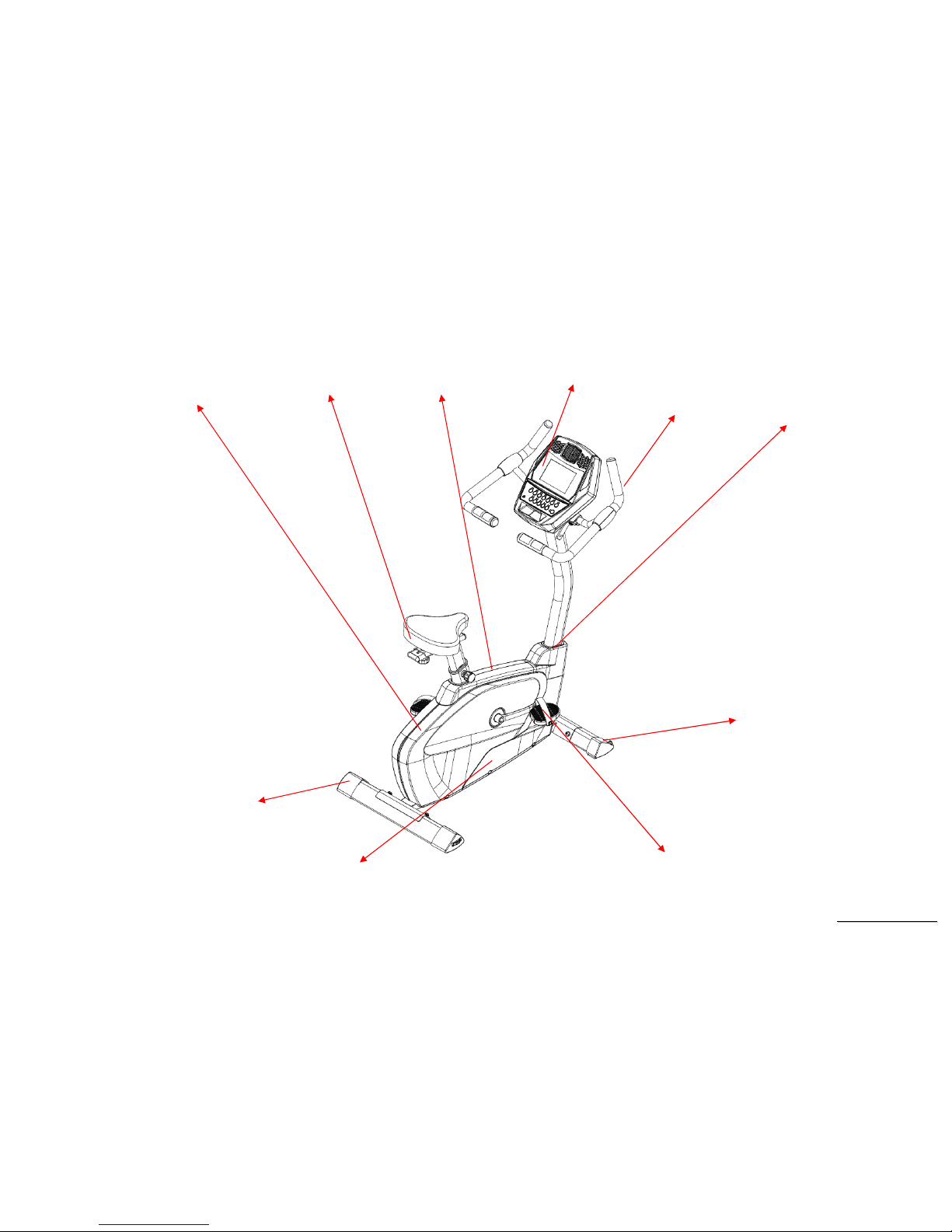
SU136 Outlines
Left Shroud Seat
Saddle Cover
Console
Handgrip
Foam
Console
Mast Cover
Stabilizer End
Cap (Rear)
Right Shroud
Pedal
Stabilizer End
Cap (Front)
SSeerrvviiccee MMaannuuaal
l
6
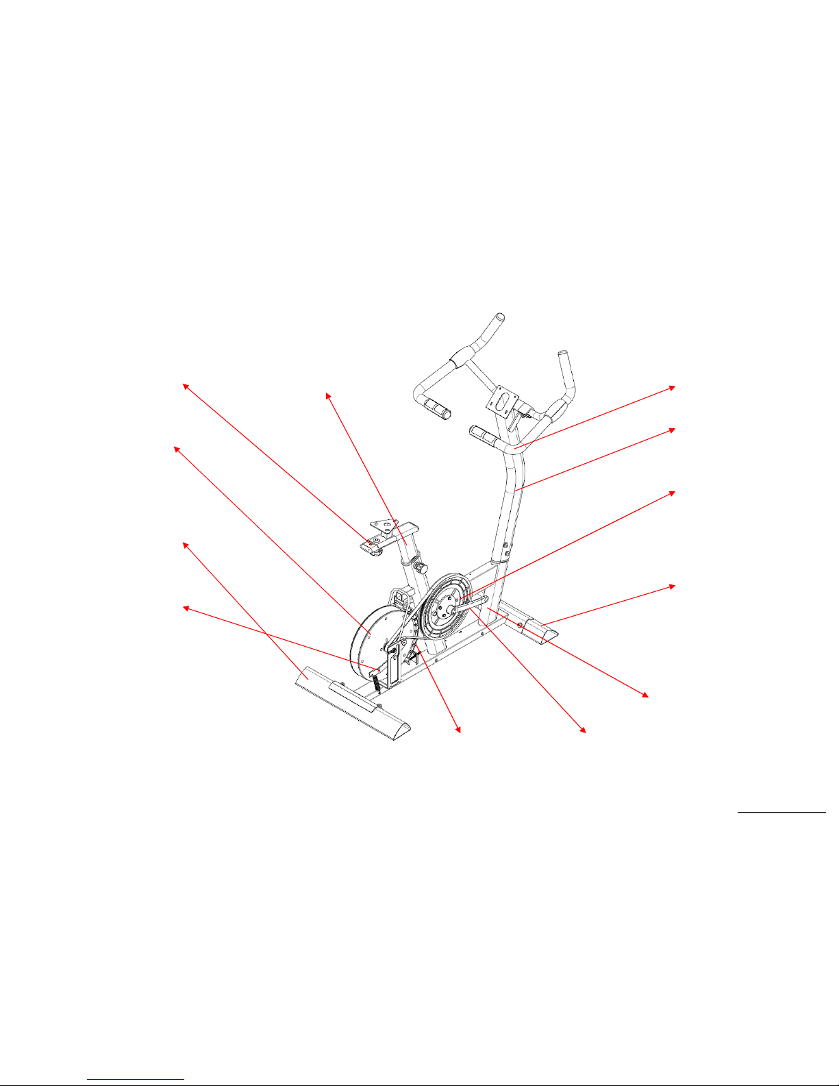
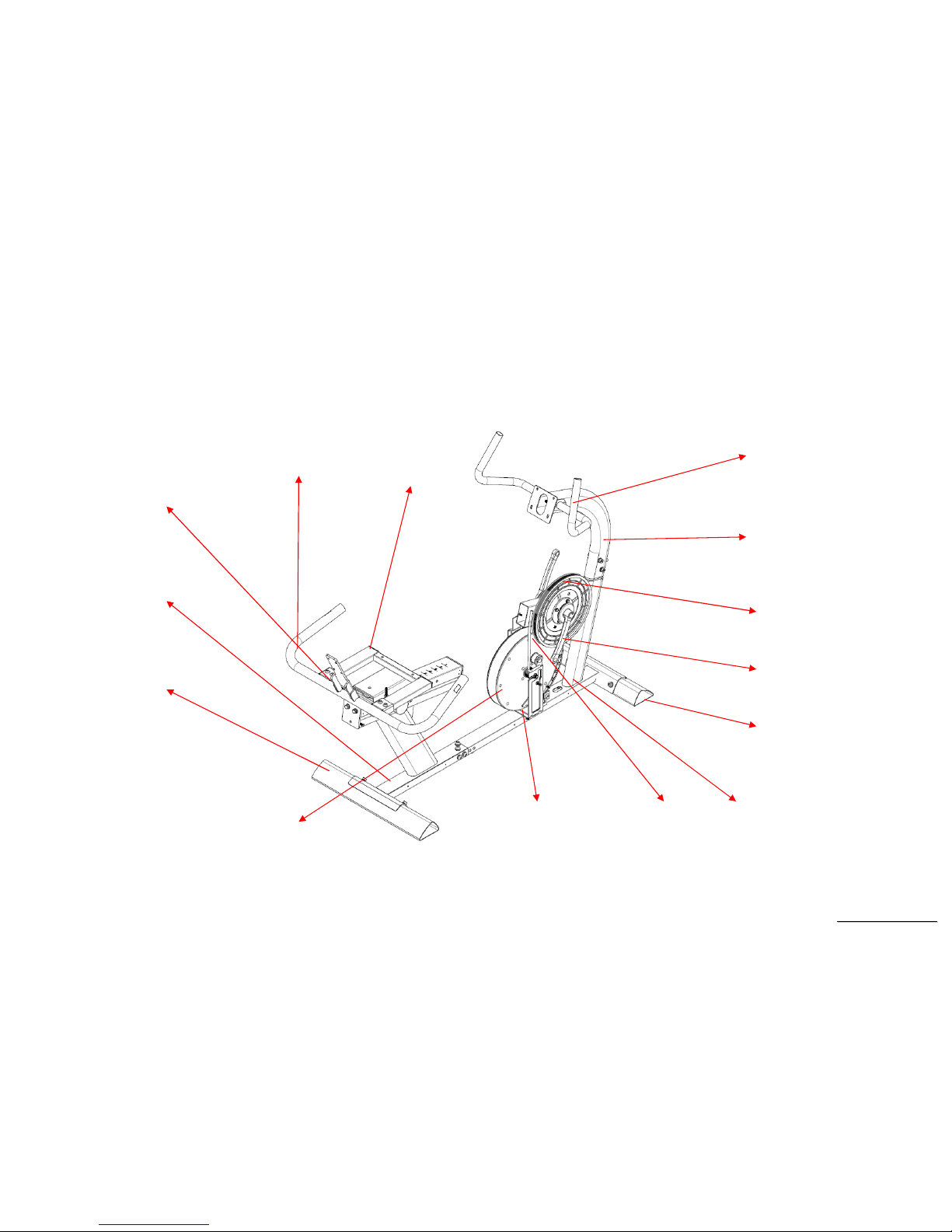
SU136 Skeleton
Inner Slide
Sliding Seat
Mount
Drive Pulley
Handle Bar
Console Mast
Rear Stabilizer
Flywheel
Idler
Bracket
Flywheel
Magnets
Mounting Plate
Crank Arm
Main Frame
Front
Stabilizer
SSeerrvviiccee MMaannuuaal
l
7
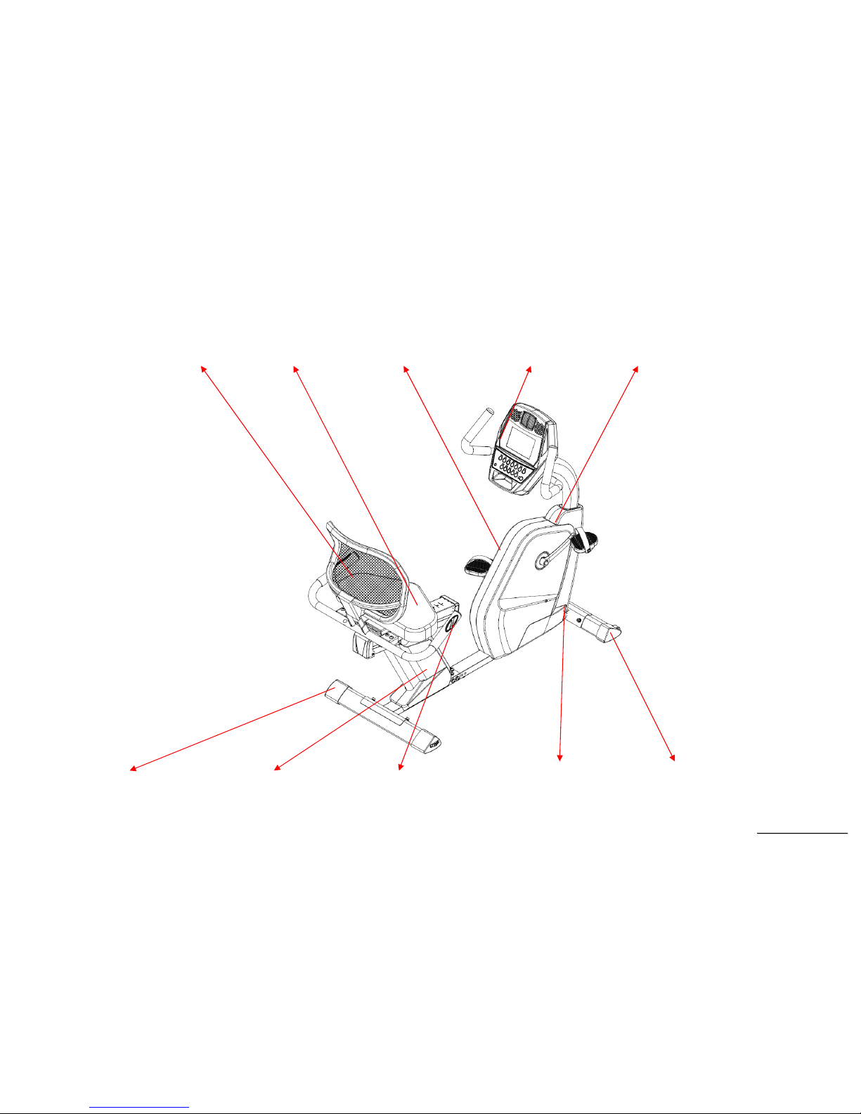
SR147 Outlines
Seatback
Seat Rear Shroud Console
Console Mast
Cover
Adjustme
nt Base
Seat Carriage
Cover
Seat Handle Bar
Front Shroud
Transportation
Wheel
SSeerrvviiccee MMaannuuaal
l
8
SR147 Skeleton
Seat Back
Bracket
Console Mast
Hand Pulse
Sensor Arm
Crank Arm
Drive Pulley
Seat Carriage
Seat Handle Bar
Front
Stabilizer
Front Main
Frame
Flywheel
Magnets
Mounting Plate
Rear
Stabilizer
Rear Main
Frame
Flywheel
Idler
Bracket

SSeerrvviiccee MMaannuuaal
l
9
2. Electronic Parts
SSeerrvviiccee MMaannuuaal
l
10
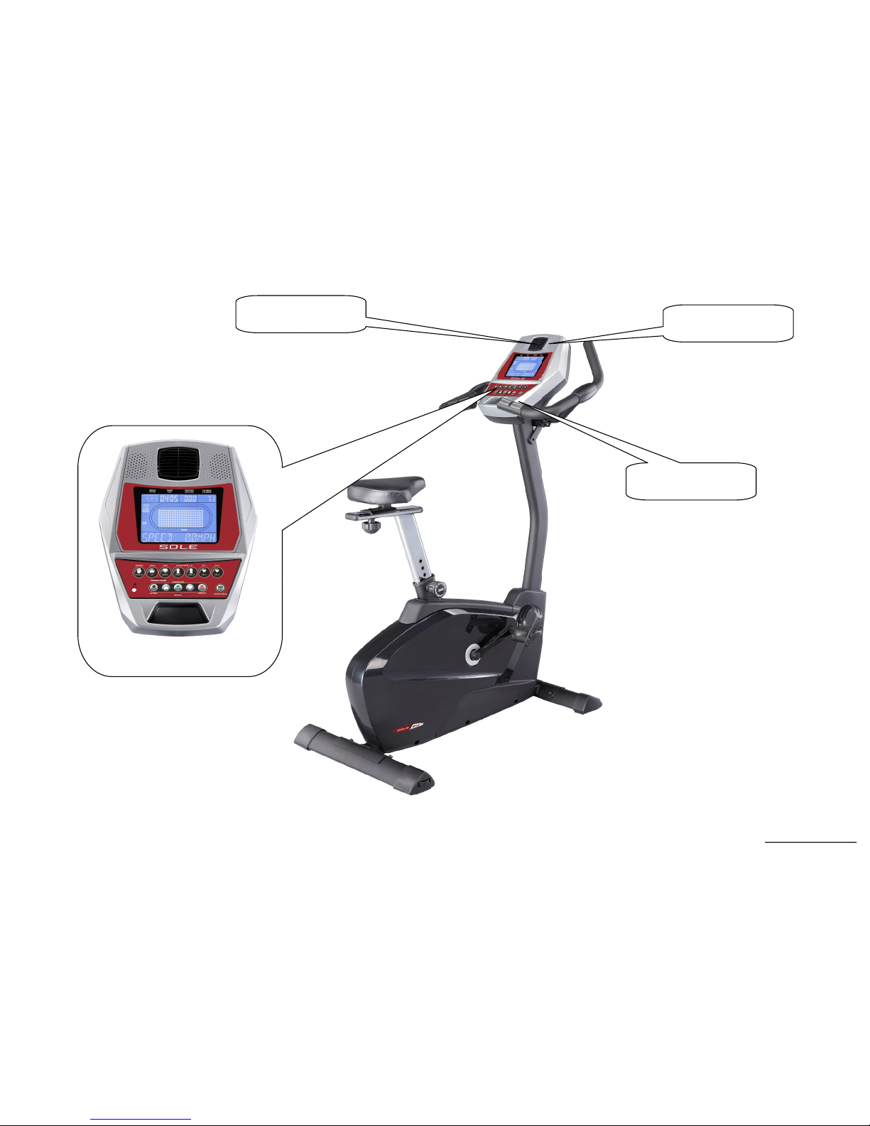
SU136 Upper Controllers
DISPLAY
Cooling FAN
Hand-Pulse
Speaker
SSeerrvviiccee MMaannuuaal
l
11
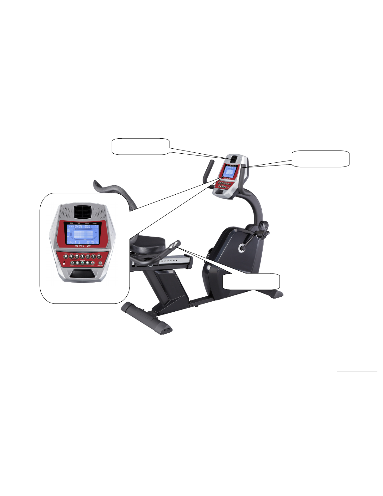
SR147 Recumbent Controllers
Cooling FAN
Hand-Pulse
Speaker
DISPLAY
SSeerrvviiccee MMaannuuaal
l
12
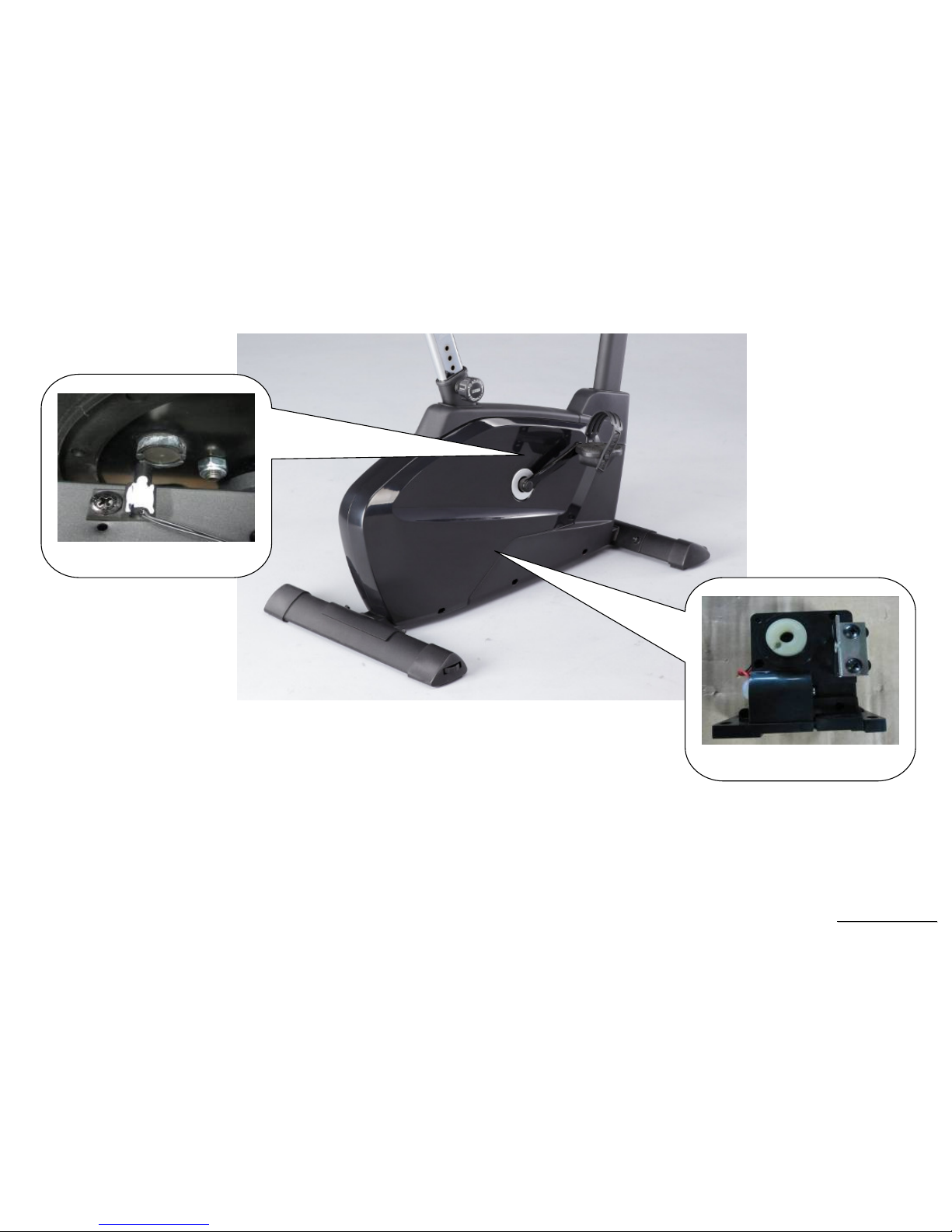
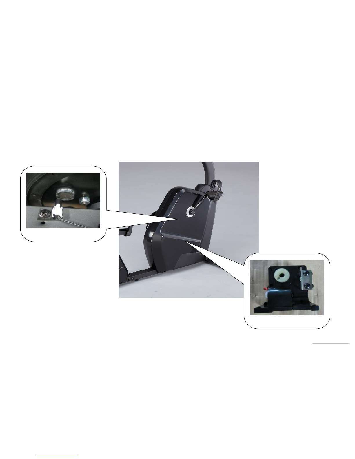
SU136 Lower Controller and Driver
SPEED SENSOR
TENSION MOTOR
SSeerrvviiccee MMaannuuaal
l
13
SR147 Lower Controller and Driver
SPEED SENSOR
TENSION MOTOR

SSeerrvviiccee MMaannuuaal
l
14
3.Electrical Configurations

SSeerrvviiccee MMaannuuaal
l
15
C
ONSOLE:
I
NTERFACE THAT CONTROLS ALL FUNCTIONS OF THE ELLIPTICAL
.
M
AIN CONTROLLER
:
The circuit board consist of the DC power supply for console、incline driver and tension motor driver, link the console to output appropriate
voltages for tension motor that control the elliptical functions.
T
ENSION MOTOR
:
It can change to increase or decrease resistance level of brake.
G
ENERAL INFORMATION
C
ONSOLE
Contains Key controls and LCD Display.
Main controller Include power supply 、 motor driver control circuit and incline control circuit.
T
ENSION MOTOR
Work voltage:DC 4.5~7.5V
Control resistance increases and decreases.

SSeerrvviiccee MMaannuuaal
l
16
4. Product Operation
SSeerrvviiccee MMaannuuaal
l
17
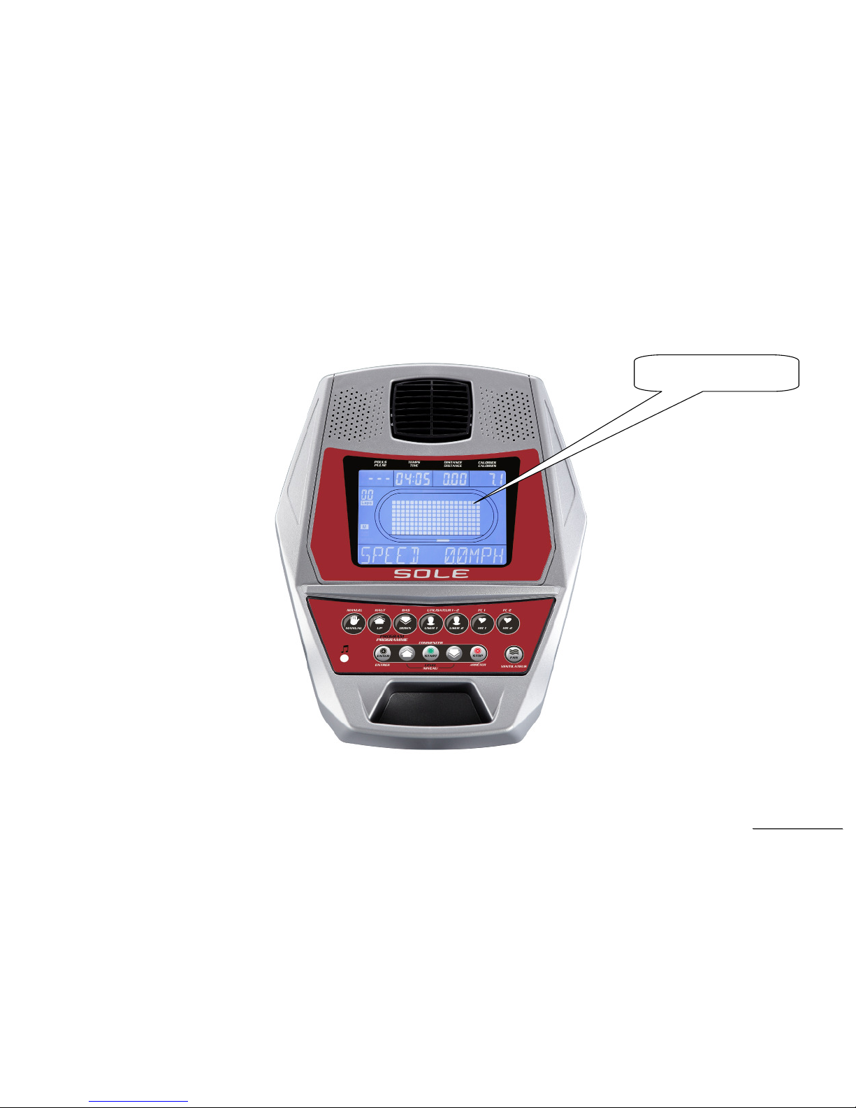
Display Windows
6.5” LCD Display
SSeerrvviiccee MMaannuuaal
l
18
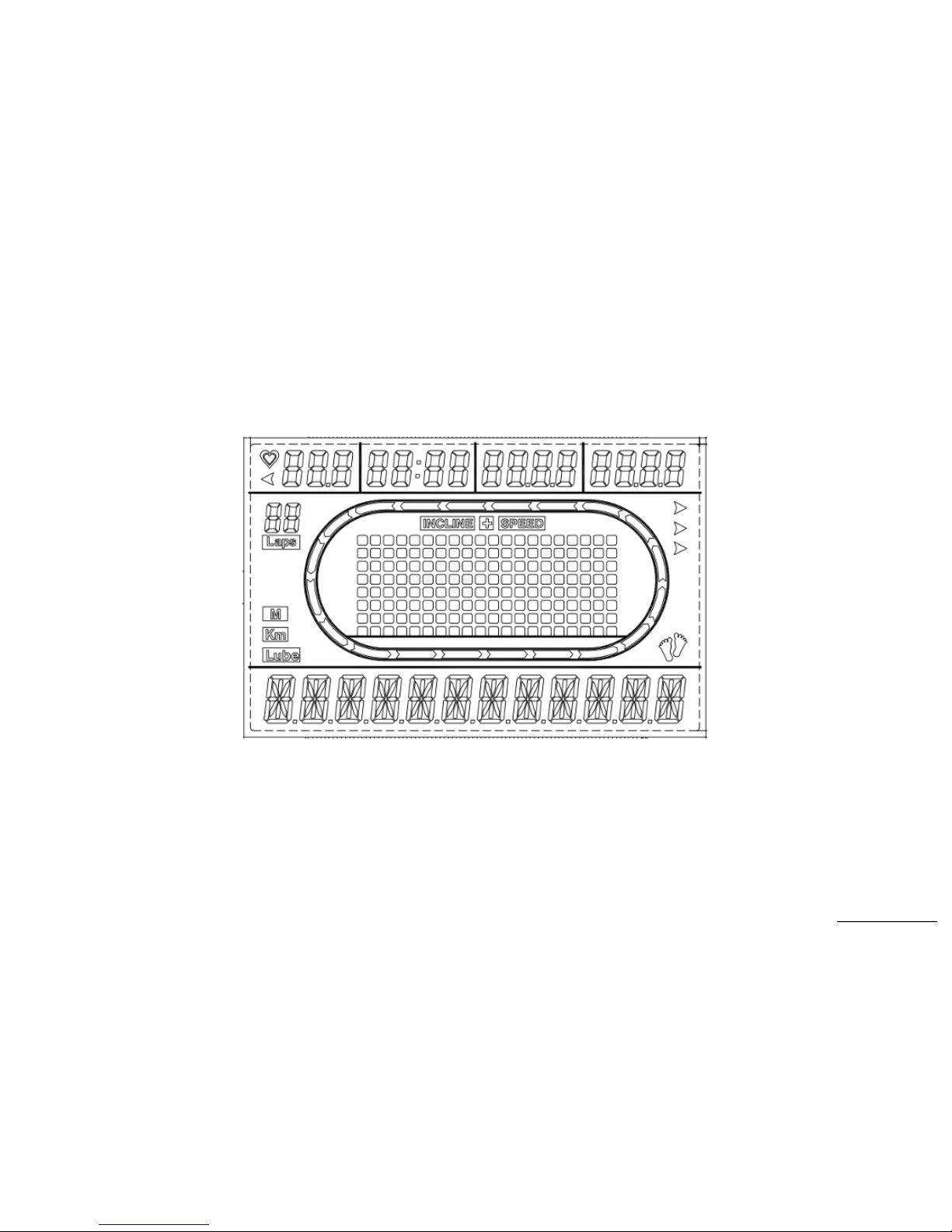
LCD Layout

SSeerrvviiccee MMaannuuaal
l
19
Operation
Window Display Mode
IDLE MODE
1.1 Each program profile and name will be displayed on the MESSAGE WINDOW sequentially.
SLEEP MODE
2.1 Pre-set: DISPLAY ON(DISABLE). You could set the DISPLAY ON/OFF by ENGINEERING MODE.
2.2 The console will not get into SLEEP MODE when the set up is “ON”, unless turn off the power. There is no RPM input in IDEL MODE, and enter
to SLEEP MODE after 20 minutes without pressing any key.
In DISPLAY MODE, LCD screen will has no display, and backlit will be off. Press any key to wake up the system, and back into IDEL MODE.
CHILD LOCK MODE
3.1 Pre-set: CHILD LOCK OFF (DISABLE). You could set the CHILD LOCK ON/OFF by ENGINEERING MODE.
3.2 The message window will display “CONSOLE LOCKED” , when CHILD LOCK setup is ON.You could setup the CHILD LOCK MODE OFF by
pressing “START” and ”ENTER” key for more then two seconds. After that it will enter to IDEL MODE.
3.3 All keys will be no action when CHILD LOCK MODE is active.
EXERCISE MODE(QUICK START)
4.1 In IDEL MODE, press START key enter to MANUAL MODE.The age, weight is presetting value.Time counting is count up from 00:00. All
countable data will count up from “0”, and resistance is count up from “1”.
4.2 You could chose the program by pressing the key: MANUAL、PROGRAM、USER1、USER2. And then, press “START” key to start the workout.
All parameter will be the preset value.
PAUSE MODE
5.1 Press “STOP” key enter to PAUSE MODE, and exercise parameters will be recorded.Message window will display “PAUSE”, and upper window
will display the recorded exercise parameter.
5.2 In PAUSE MODE, it will display PAUSE
5.3 It will enter to IDLE MODE after waiting by five minutes without pressing any key in PAUSE MODE.
5.4 The ramp incline level should back to “1” when the resistance level is “1”. The position of tension motor and ramp incline should back to the
preset level before it pause when press “START” key.

SSeerrvviiccee MMaannuuaal
l
20
END MODE
6.1 The message window will display “ END OF WORKOUT” .
6.2 END MODE workout information
6.2.1 Display exercise data in message window each three seconds.
6.3 When the time counting is end, and END MODE display is finished without pressing any key in 30 seconds.The system will enter IDLE MODE.
RESET MODE
7.1 In IDLE MODE, press STOP key for more than three seconds will enter to RESET MODE and reset the system. If the system is in CONSOLE
LOCK MODE you have to quit CONSOLE LOCK MODE first, and you can execute the RESET MODE.
7.2 The message window will display CONSOLE RESET two seconds, and finished the reset. After that, the system is in IDLE MODE.

SSeerrvviiccee MMaannuuaal
l
21
Function
SPEED
Display the current speed in Kilometer mile per hour.
DISPLAY range is 0.0 to 99.9 (message bar)
WORK range is 0.0~99.9
LEVEL
Display the level position from 0 to 20
DISPLAY range is 0 to 999. (message bar)
WORK range is 0 to 20.
LEVEL preset value is 0 to 20.
Press “UP” or ”DOWN” to adjust level, each increment and decrement is 1.
TIME
TIME is either COUNT UP or COUNT DOWN. System preset is COUNT UP; if user sets the time then timer is COUNT DOWN.
DISPLAY range is 0:00 to 99:99.
WORK range is 0:00 to 99:59.
COUNT DOWN setup range is 10:00 to 99:00.
When TIME is set, the count will go to zero.
In RUN Mode, press “STOP” button to save value of time and enter “RUN Mode” again that value will continue count up time.
LAPS
Display the total working laps quantity.
DISPLAY range is 0 to 99.
WORK range is 0 to 99.
Displays total laps quantity.
DISTANCE
Display the current distance in kilometer or Mile.
DISPLAY range is 00.0.0 to 9999.
WORK range is 000.0 to 9999.

SSeerrvviiccee MMaannuuaal
l
22
CALORIES
Displays the cumulative calories burned at any given time during your workout.
DISPLAY range is 00.0.0 to 9999.
WORK range is 000.0 to 9999.
PULSE
Displays the heart rate beat by using hand pulse or receiver. When use receiver, a chest belt must be worn.
DISPLAY range is 0 to 999.
WORK range is 72 to 200 BPM.
In RUN Mode, if the Elliptical doesn’t have a signal for 8 seconds then display value will become “0 ”.
SSeerrvviiccee MMaannuuaal
l
23
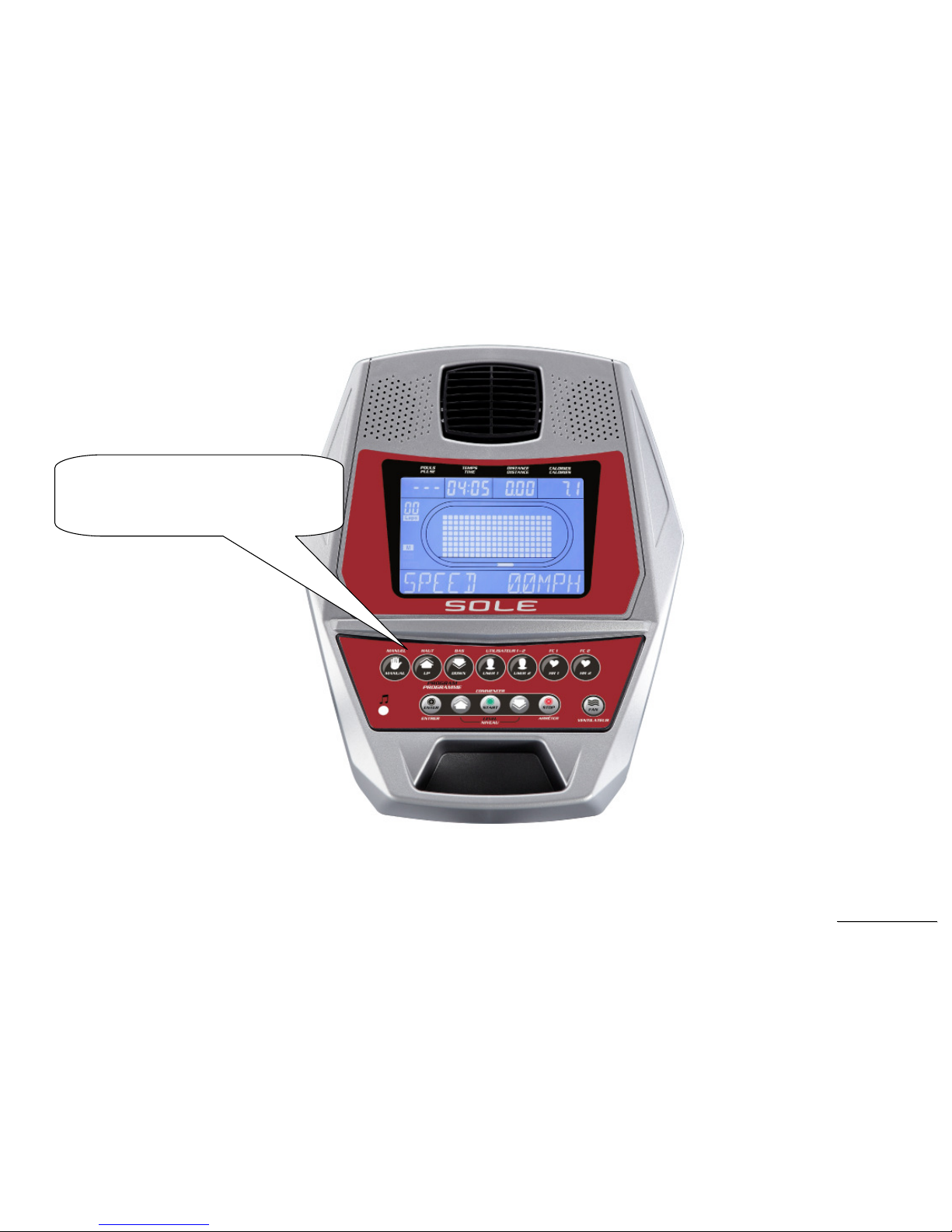
Function Button Locations
Manual, Program Up,Program Down,
User 1,User 2,HR1,HR2,Enter,Level
up,Start,Level down,Stop,Fan

SSeerrvviiccee MMaannuuaal
l
24
Function Button In Main Mode
READY MODE
STOP button: Non-function.
START button: Pressing “ START ” button to start Elliptical, When pressing “START” button, there will be 3 second final count down on window
display, then machine starts running. In MANUAL, Elliptical starts at MIN LEVEL .
LEVEL UP button: If user doesn’t enter a setting then this button is non-functional.
LEVEL DOWN button: If user doesn’t enter a setting then this button is non- functional.
PROGRAM UP Button:select a program
PROGRAM DOWN Button:select a program
USER 1:select user 1 setting program
USER 2:select user 2 setting program
HR 1:heart control program
HR 2:heart control program
ENTER KEY::::Press ENTER key enter to parameter setting, and confirm the every setting by pressing ENTER key. Press START key to finish
the setting.
FAN BUTTON:switch cooling fan function on or off

SSeerrvviiccee MMaannuuaal
l
25
RUN MODE
STOP button: press “STOP” button to stop Elliptical.
START button: non-functional.
ENTER button: non-functional.
LEVEL UP button: Press the button to increase your level and each increase is 1.
LEVEL DOWN button: Press the button to decrease your level and each decrease is 1.
PROGRAM UP Button:select a program
PROGRAM DOWN Button:select a program
USER 1: non-functional.
USER 2: non-functional.
HR 1: non-functional.
HR 2: non-functional.
ENTER KEY::::
Press ENTER key to switch the exercise data when you are workout. If the display information is the latest data , press DISPLAY key the
message window will change to auto display every four seconds. The information as below,
1. 『TIME XX:XX』、『PROGRAM NAME』、『DISTANCE XX.X K』
2. 『SPEED XX.XMPH』、『SPEED ** RPM』、『WATTS XXX』
3. 『CALORIES XXX』、『LEVEL XX』、『PULSE XXX』
FAN BUTTON:switch cooling fan function on or off

SSeerrvviiccee MMaannuuaal
l
26
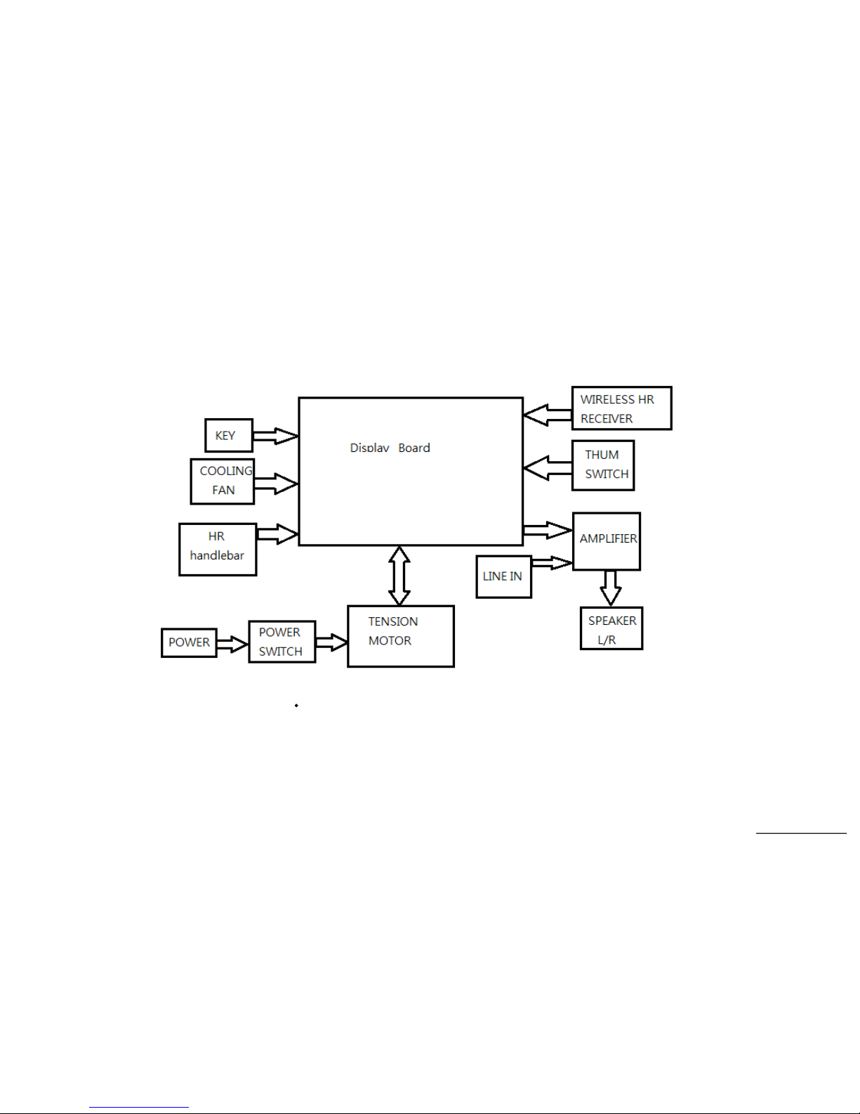
5. Unit Block Diagrams
SSeerrvviiccee MMaannuuaal
l
27
Bike Configuration
 Loading...